Initially, I wanted to use a 74F381 (4-bits ALU) and a 74HC574. Then I tried to extend the 4-bits add function to 8 bits but cascading is hard because there is no carry output, but propagate and generate signals. The Generate signal could be used alone when the carry input is not used but apparently it needs an inverter. From there, it went downhill.
Then, looking at my notes at https://hackaday.io/project/8121-discrete-yasep/log/28438-what-chips-for-the-alu I saw that I had the ideal solution. From the datasheet :
The IDT7381 is a high-speed cascadable Arithmetic Logic Unit (ALU).
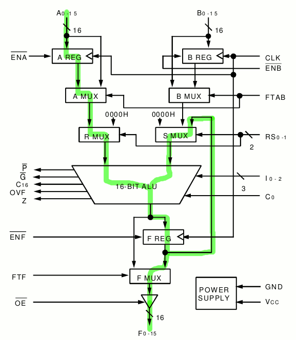
These three-bus devices have two input registers, an ultra-fast 16-bit ALU and 16-bit output register. With IDT’s high-performance CMOS technology, the IDT7381 can do arithmetic or logic operations in 25ns. The IDT7381 functionally replaces four 54/74S381 four-bit ALUs in a 68-pin package.
The two input operands, A and B, can be clocked or fed through for flexible pipelining. The F output can also be set into clocked or flow-through mode. An output enable is provided for three-state control of the output port on a bus.
The IDT7381 has three function pins to select 1 of 8 arithmetic or logic operations. The two R and S selection pins determine whether A, B, F or 0 are fed into the ALU. This ALU has carry-out, propagate and generate outputs for cascading using carry look-ahead.
The advantages are pretty significant :
- only one chip is needed for all the functions (computation and latching)
- it's 16-bits wide (and not just 4 or 8 bits)
- it draws less power
- it's faster (it easily reaches 40MHz, providing a 20MHz square signal output).
- No programming is required, just set the 16-bits divider value on the A port and get the divided frequency on the MSB of the result (F15 bit).
- The remaining output bits could be used to address a fast SRAM to generate arbitrary waveforms (I would need a fast DAC, such as a RAMDAC. Oh wait: I have RAMDACs).
- Another pretty useful feature is the ability to latch the inputs. This provides a glitch-free frequency change, since my hex rotary switches are pretty dirty. From there on, it's possible to cut the connexion between the rotary switches and the port, under software control, with 74HC165 and 74HC595, to smooth the frequency changes with a microcontroller or a Pi.
The chip would be used this way :

The connexions are:
- Input B : unused, tied to GND.
- Input A : Division ratio, 16 bits coming from the rotary switches and the 74HC595.
Value 0 is detected as "bypass" value. It should be FFFF (with the carry input set) but then the digital reading would be harder to interpret. - Output : divided frequency on F15
- /ENB : pointless, tied to GND.
- /ENA : one pulse low to latch the new frequency. Tied to GND initially for manual operation, such that it is updated at every cycle.
- FTAB : GND (flow-through disabled)
- /ENF : GND (enable the F register during every cycle)
- FTF : GND (no flow-through, should reduce the jitter)
- CLK : clock input (40MHz, can it go faster ?)
- /OE : GND (enable the F port output)
- C0 : GND (Carry in. I thought about feeding a noise generator/LFSR to add jitter, let's see later)
- C16, OVF, Z, P, G : open/unconnected
- RS0, RS1 : 00 (select operands A and F)
- I0, I1, I2: 110 (addition)
It's actually pretty simple : except I0 and I1 all fixed inputs are GND :-)
 Yann Guidon / YGDES
Discussions
Become a Hackaday.io Member
Create an account to leave a comment. Already have an account? Log In.