A.K.A. the "Blonde Power"
As presented in Science time (I): Artificial Neural Network-based mechanical faults diagnosis (I), this system is based on a hardware implementation of artificial neural network encapsulated into an IC called HM2007 which is used primarily for spoken words (speech) recognition.
Searching the internet for schematics based on this circuit will show the classic design and two PDFs - the datasheet and the errata specifying a bug design and a workaround which does not completely give the desired results.
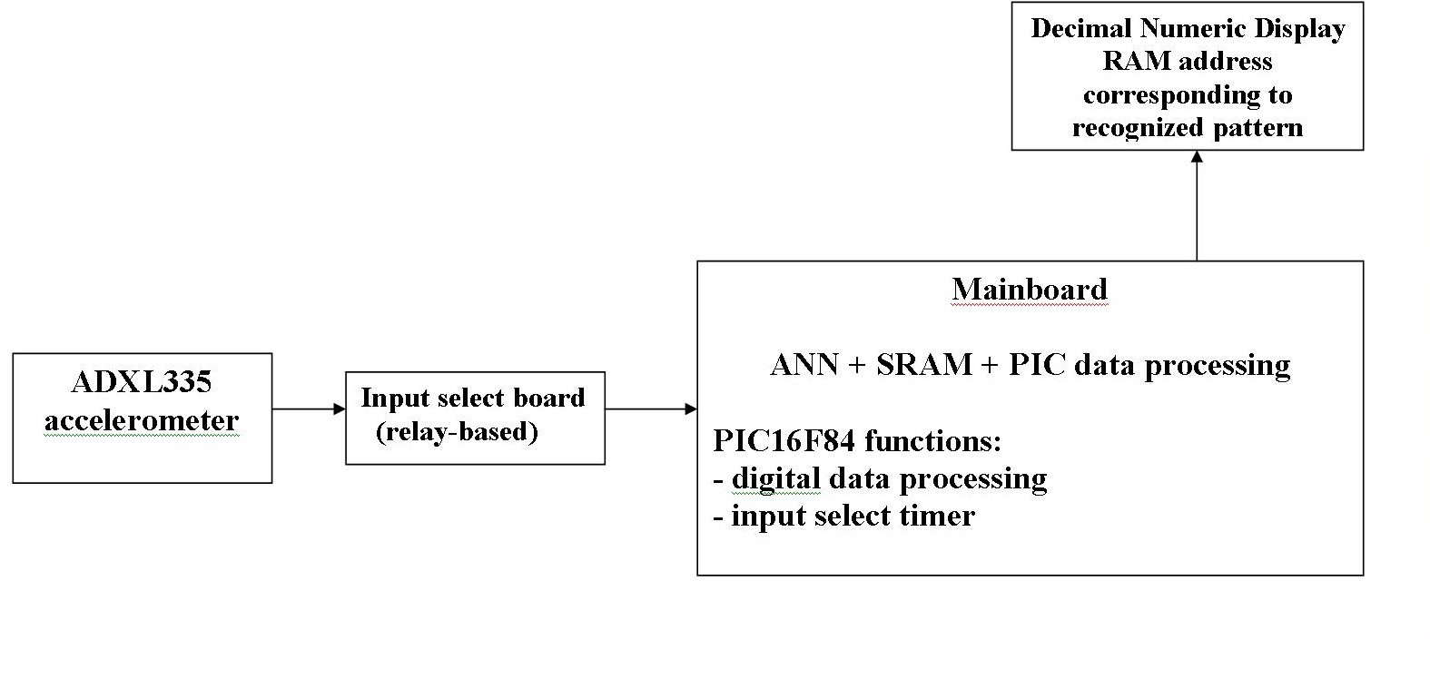
First, the block schematic:
- ADXL accelerometer
monitors the vibrations on the wheel shaft and transmits all three connected X, Y and Z axes signals as an output;
- relay board for input selection
According to the HM2007 datasheet and the jumper settings on the mainboard, the "listening" time is 0.9 seconds. Less than that - ANN says "word too short". More than that and ANN outputs the error "word too long". So the ANN input is switched to ADXL output for 0.9 seconds, and for some 0.3 seconds it is switched to GND.
Contains a 12V relay and some signaling LEDs: blue for "Vibra Input" selection and red for "GND" selection.
"STAB" comes from "stabilizer" and it means "power regulator". Turns 12V to 3.3V needed by ADXL335.
Relay handling is done by the PIC16F84 through an ULN2803A open collector circuit.
Connector in left side:
| PIN | DIRECTION | FUNCTION |
| 1 | INPUT | +5V (extra confirmation) |
| 2 | INPUT | +12V (ULN+relay+STAB PWR) |
| 3 | OUTPUT | +3.3V (PWR ADXL335) |
| 4 | OUTPUT | HM2007 VIBRA IN |
| 5 | INPUT | ADXL335 SIGNAL OUTPUT (X+Y+Z) |
| 6 | GND | |
| 7 | INPUT | PIC RA1 RELAY CMD |
| 8 | GND |
Before any comments such as "why wasting an entire ULN2803 circuit when you could just use a transistor", please understand that I worked using whatever components I can find in the drawers or recover from malfunctioned devices I find in sometimes abandoned warehouses at work.
- Decimal Numeric Address Display board
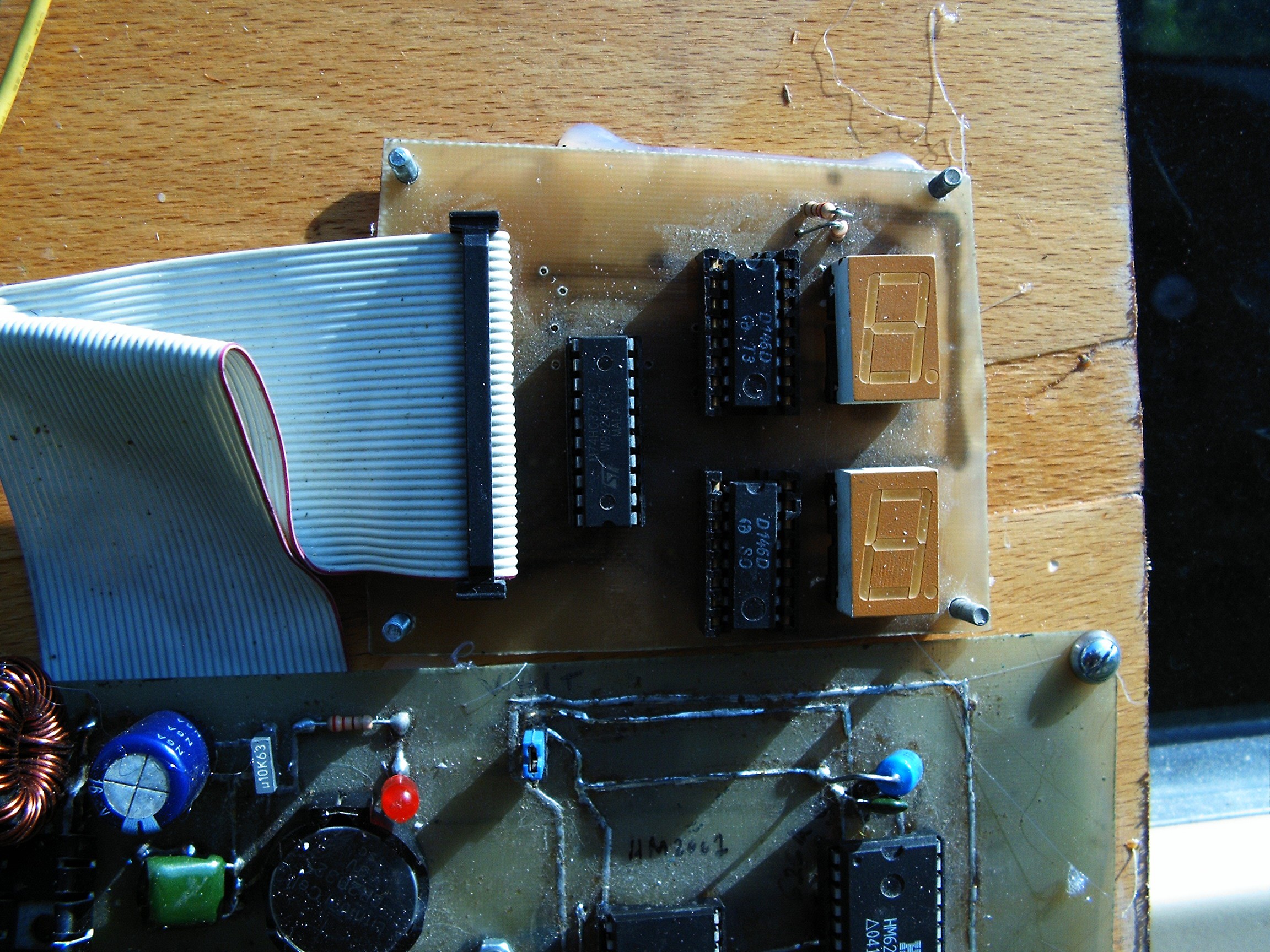
Displays the error signals or SRAM addresses issued by the HM2007 when certain conditions are met.
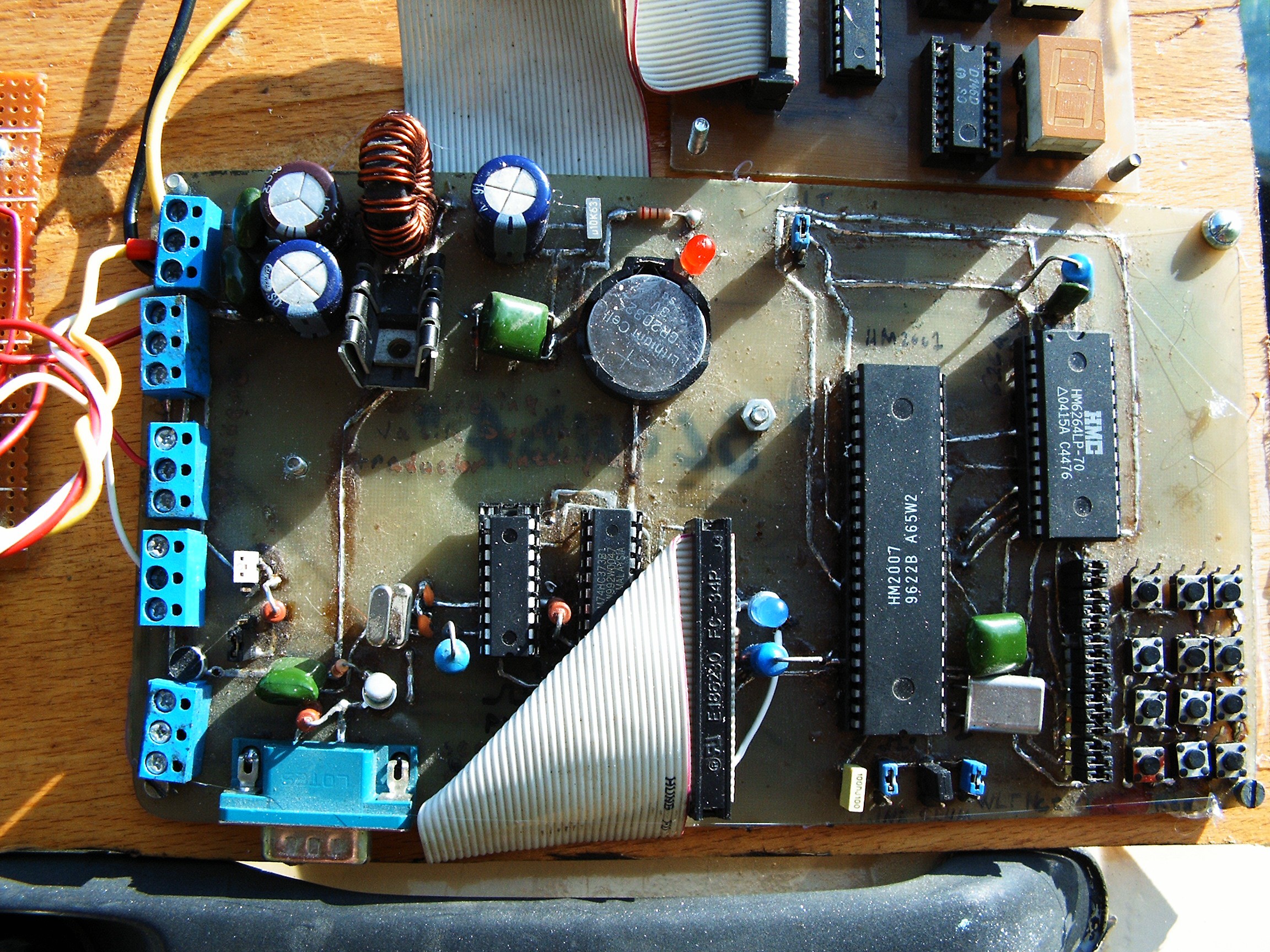
- mainboard
Contains HM2007 (ANN voice/pattern recognition chip), HM6264 (64k SRAM, the Blonde Brain),
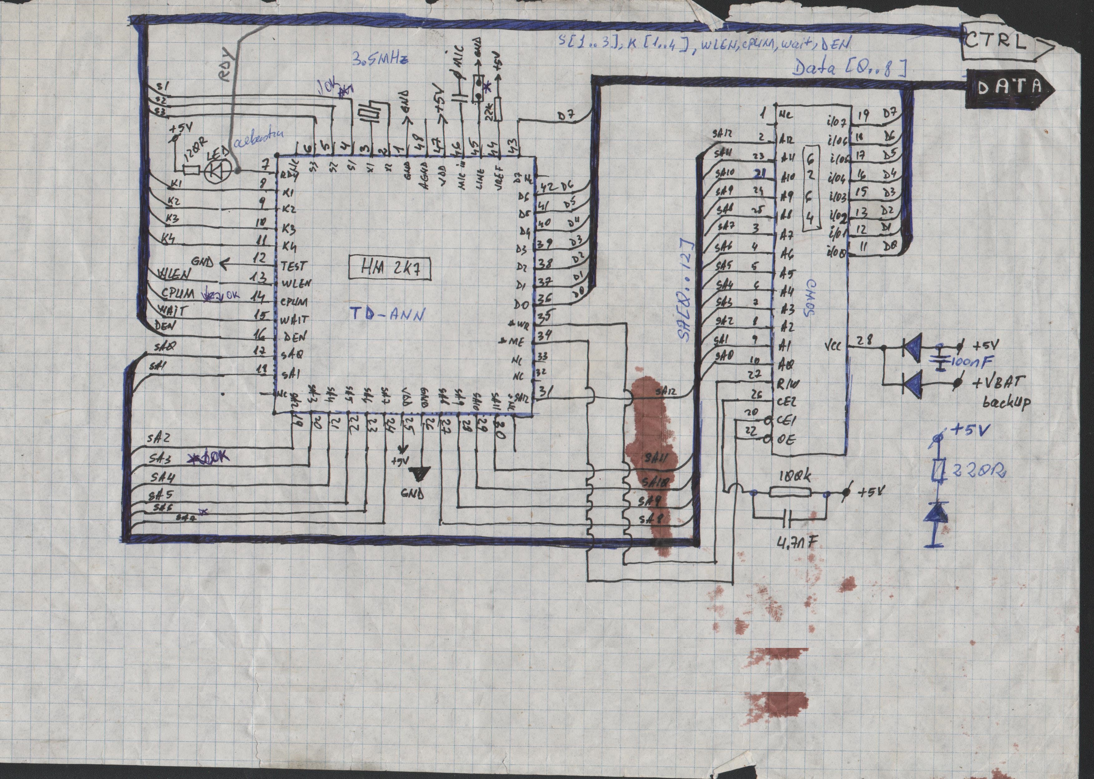
a keypad for user interaction (train data, clear data, address select), a PIC16F84, another power supply and some jumpers.
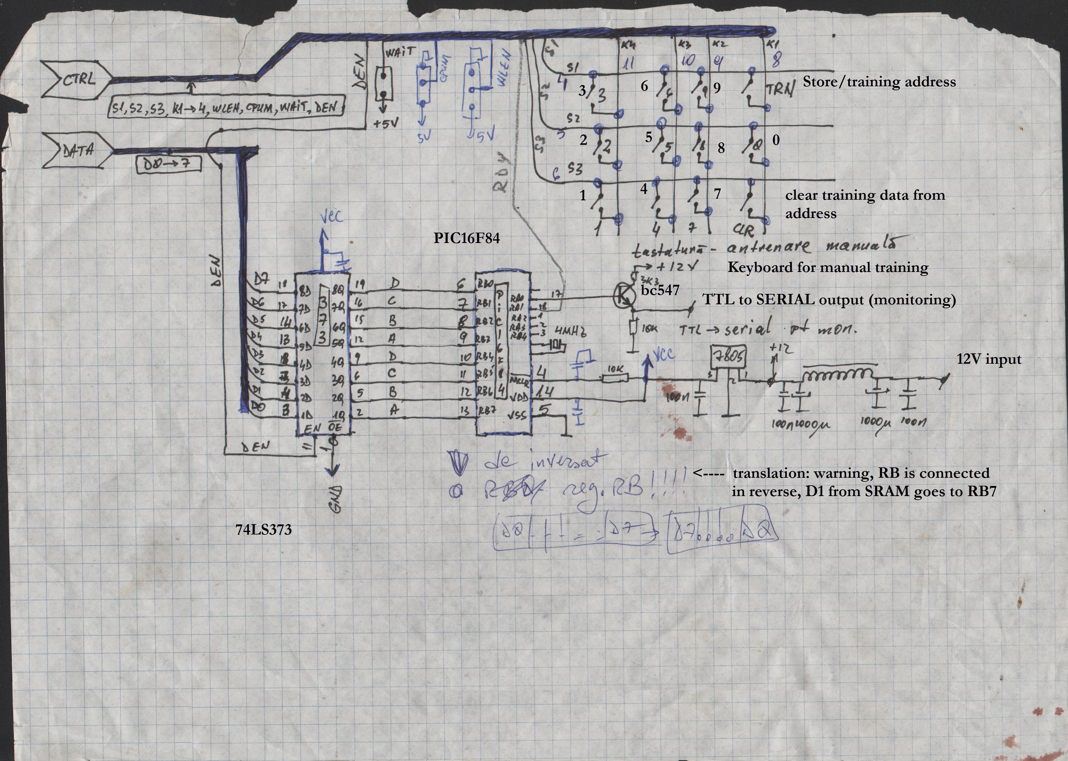
These pages are scanned from my old magic spell notebook. It was drawn many many years ago, at the dawn of internet era in this part of the world (at the end of the 90s).
So for this project I'm using an old board I designed and made during the
old days of CadSoft Eagle 4, when I did not know that program could handle data buses.
Schematics look better on those papers.
So how does it work?
Let's say we are trying to recognize some voice commands. At system startup, there will be two leds active: a red led (pwrOK) and a blue led (READY).
First we need to train the chip so we press the address (for example 01). At this time the RDY line go HIGH (Blue LED off). Pressing "TRN" will turn the RDY line back to LOW (Blue LED on) - ANN is waiting for an input - and we can speak the word. WLEN (word length) jumper is set to 0.9 seconds, so according to the datasheet we've got 40 locations available in the SRAM memory to store the training data [spoken words].
When training the ANN with data (patterns, or words, or voice commands), we need A LOT of training data. Because if we train it saying "three", it will react positive when we say "thirteen" or "thirty". If there's not enough data, it cannot make the differences.
Now - working with repetitive patterns (vibrations) is easier for the ANN. But if we are not careful, we get the "word too long" error, so this means we have to periodically separate the ANN input line from the vibration source. This is where the relay input select board is coming.
Alright. Now what's up with that PIC16F84?
Well, it performs two functions:
- 1. getting the address bus numbers and do something with them - not implemented yet;
- 2. When RDY signal gets low (this usually means keypad interaction), the 0.9s/0.3s input selection is suspended. When RDY signal goes back high, relay waits for another 0.5 seconds before switching back to VibraIn input. I need this extra time interval for in-house testing. I'm using a drilling machine with different RPMs in order to check if this is working.
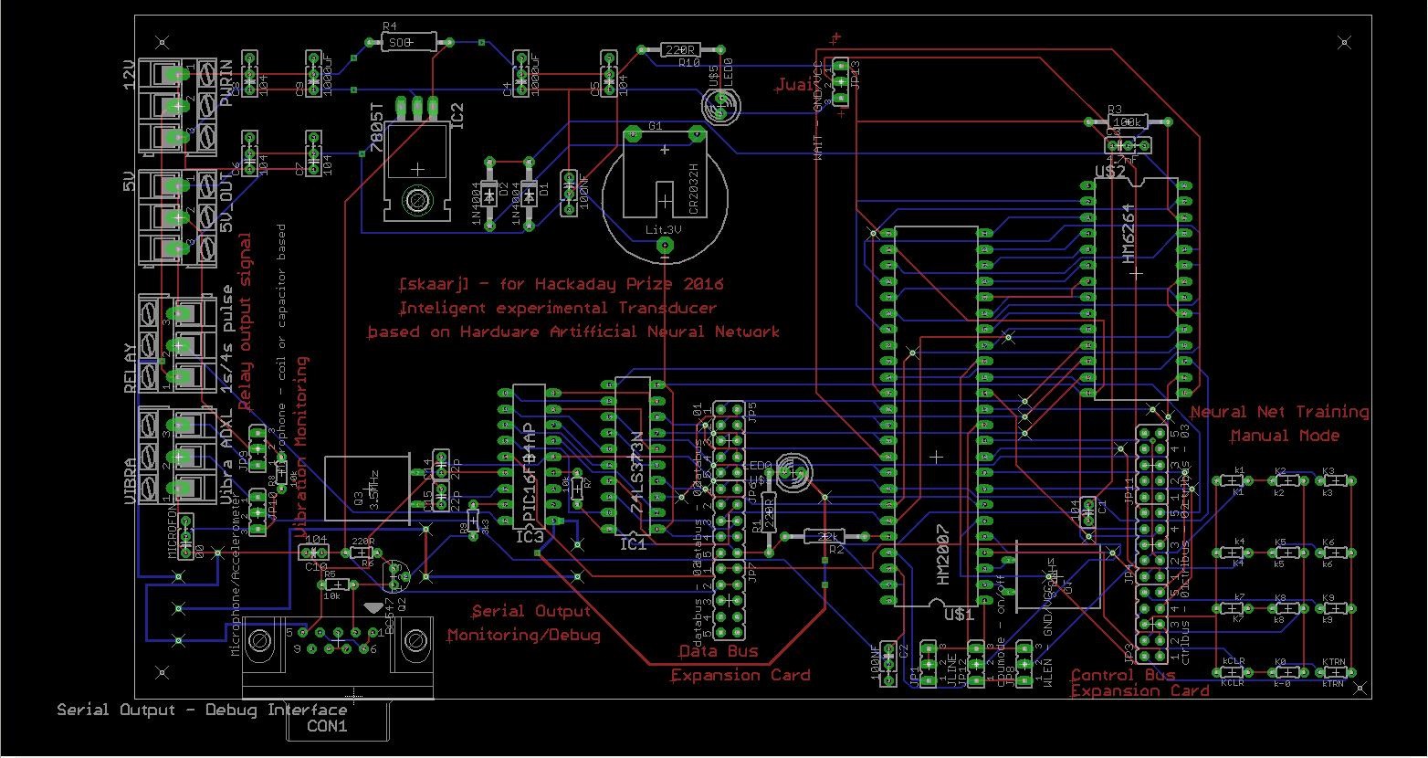
Mainboard PCB
This is my first schematic I ever made in EAGLE. It was version 4, libraries were incomplete and I had to replace keypads and microphone with whatever components (libraries) I could find.
And this is the final system:
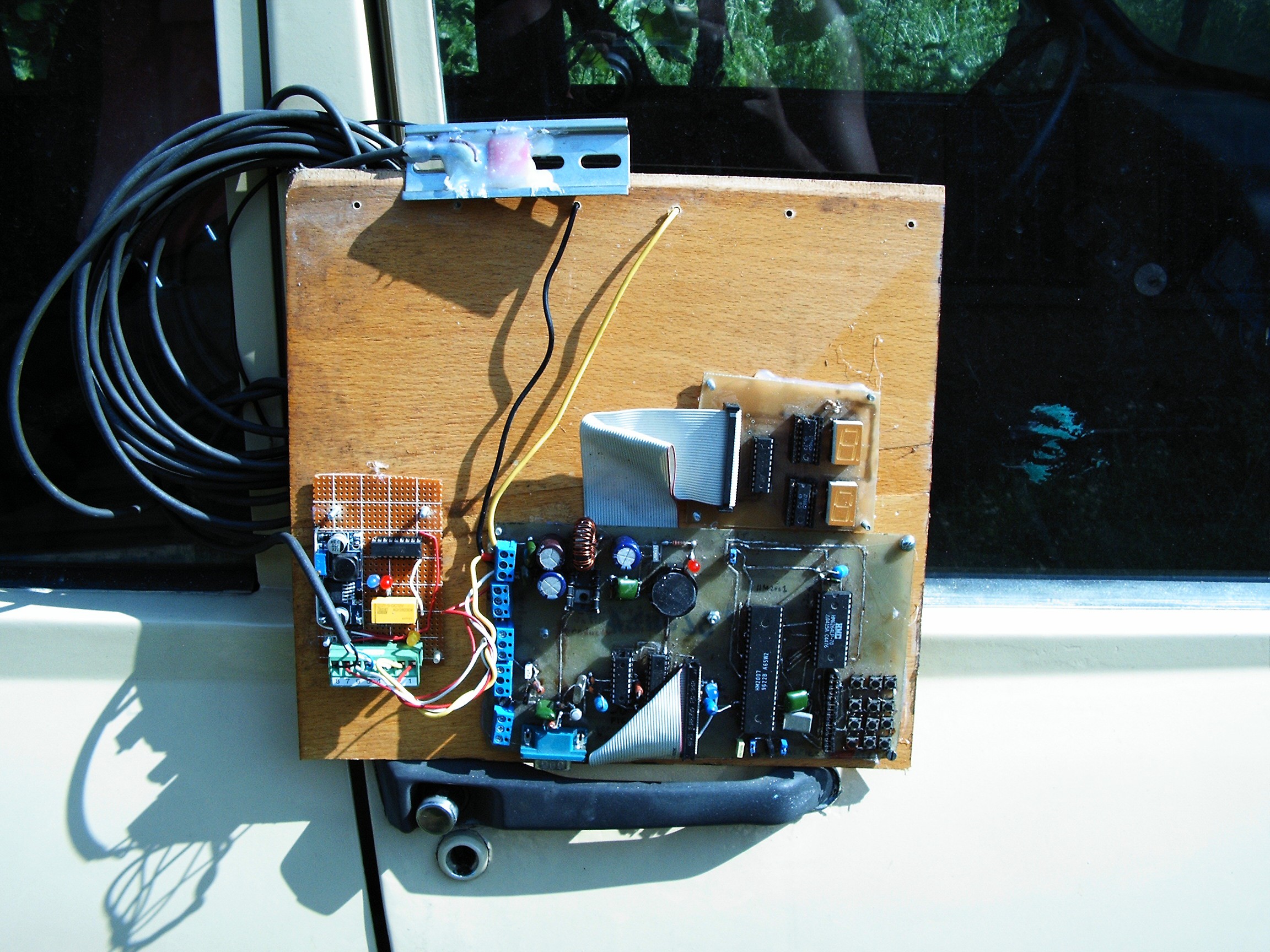
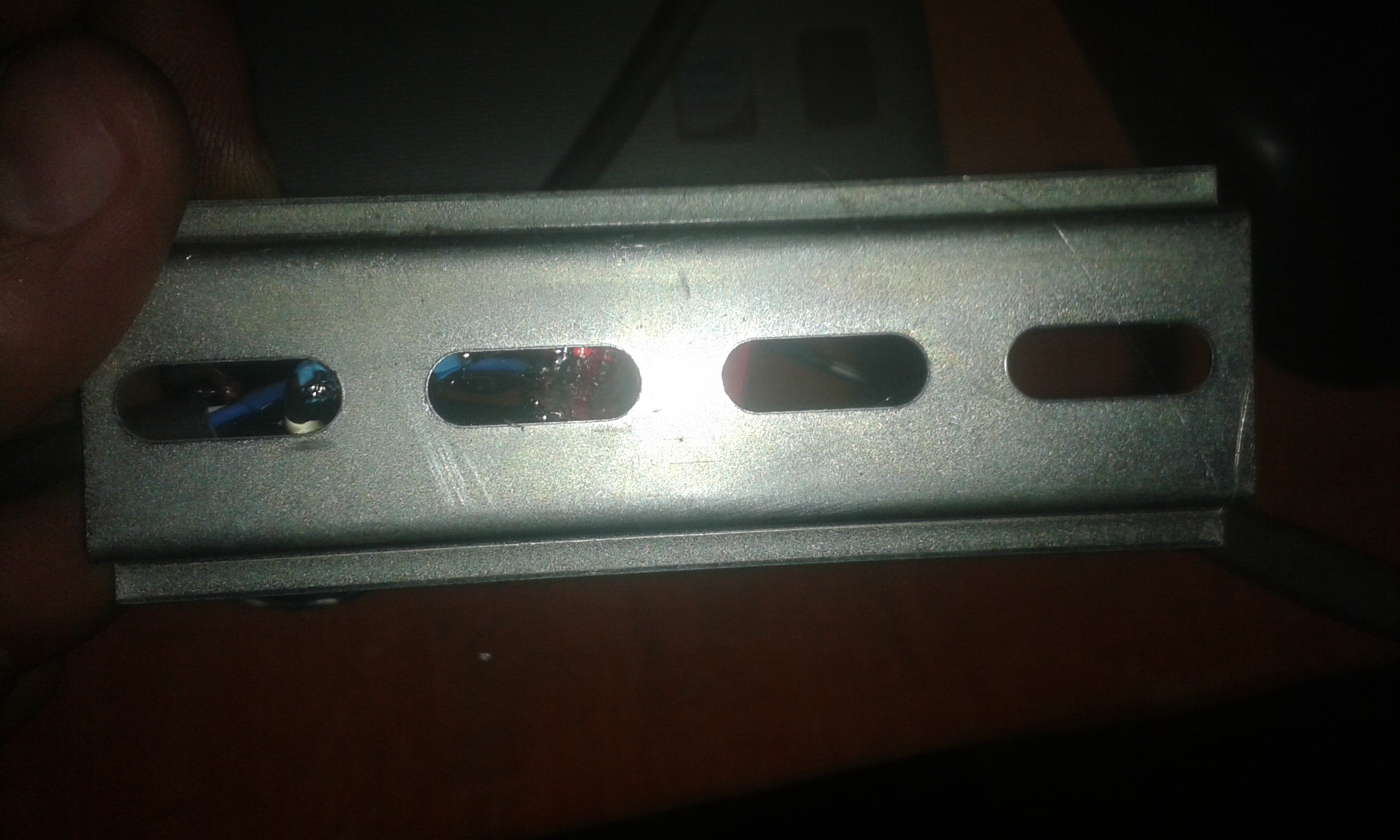
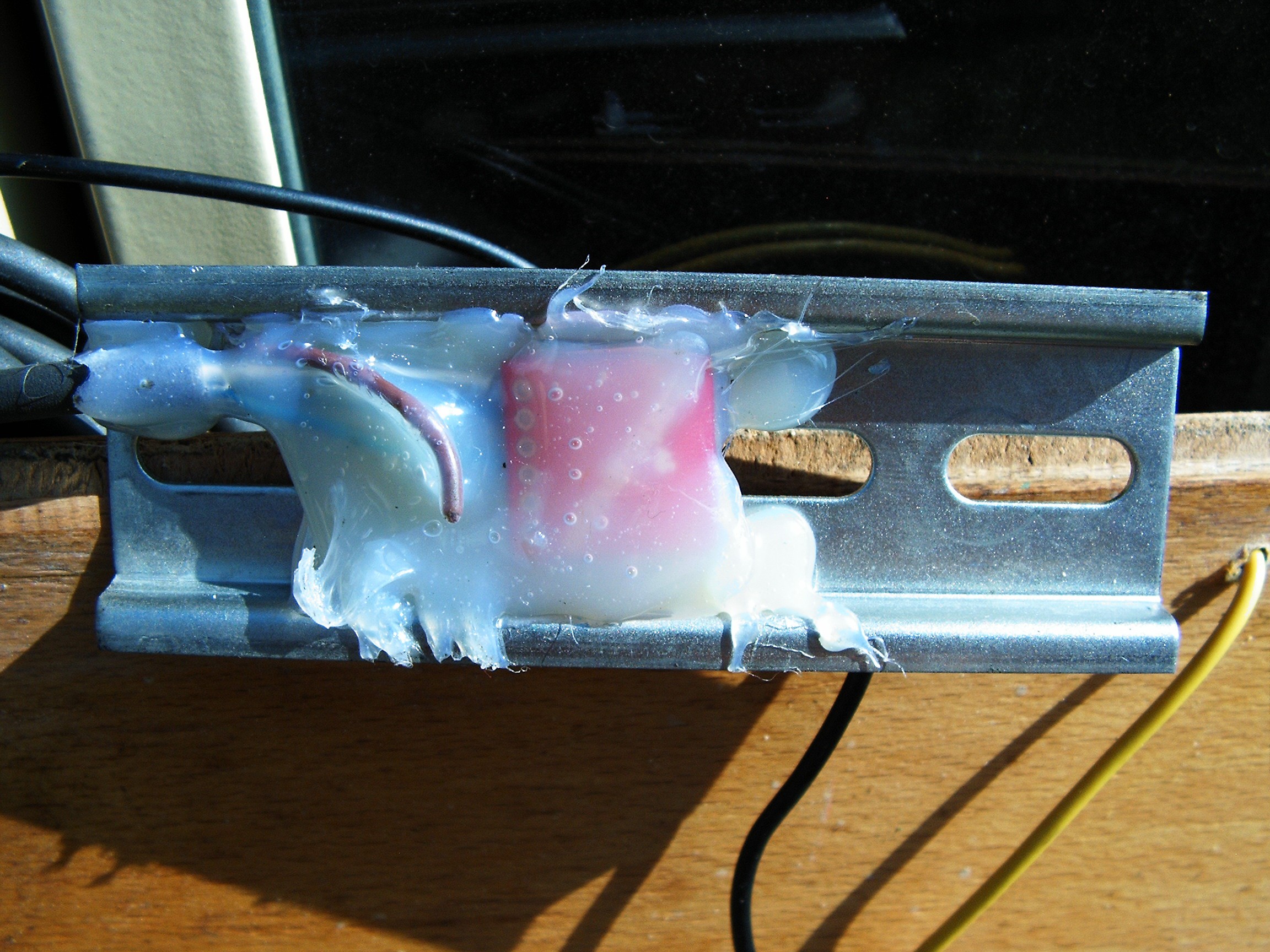
On top there's the ADXL335 accelerometer, installed on a metal base used for automatic fuses:
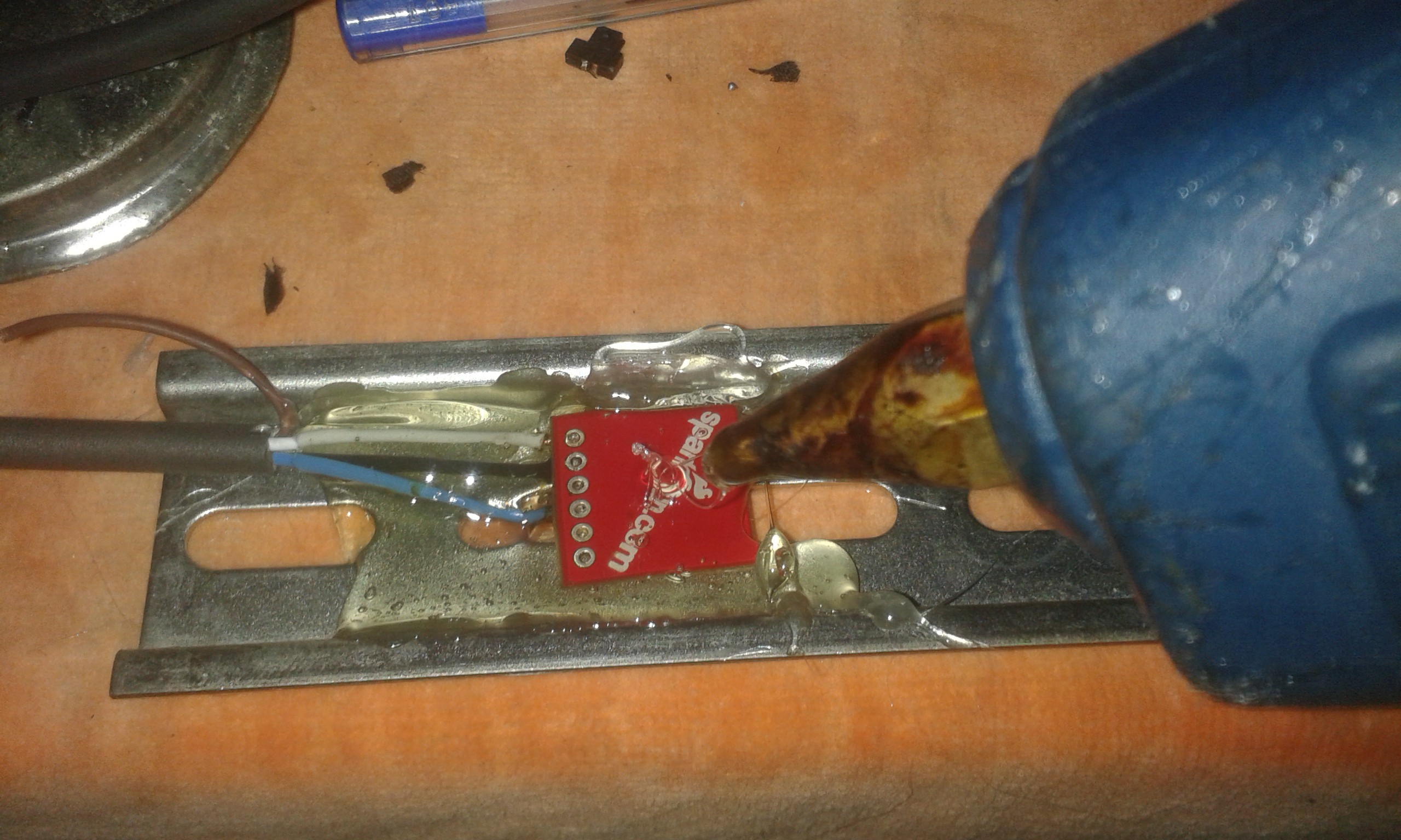
ADXL pressed and fixed with melted plastic
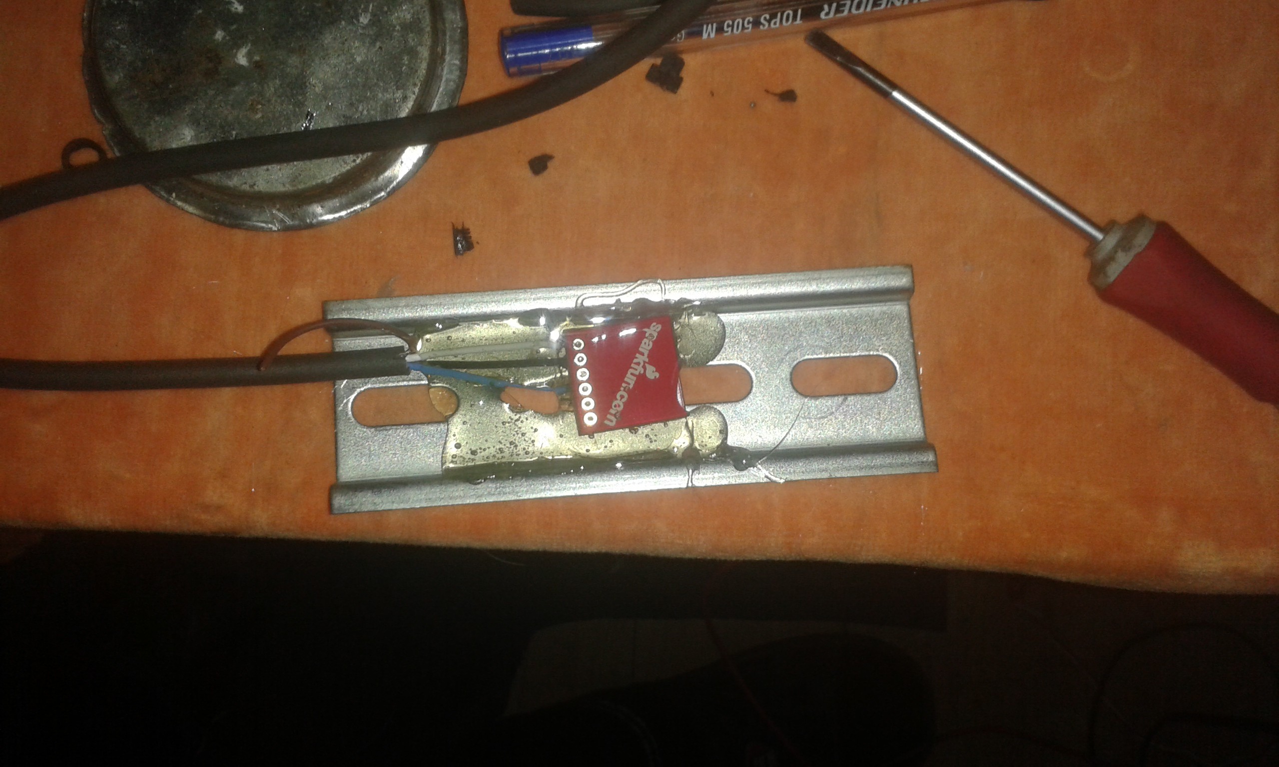
let it cool down
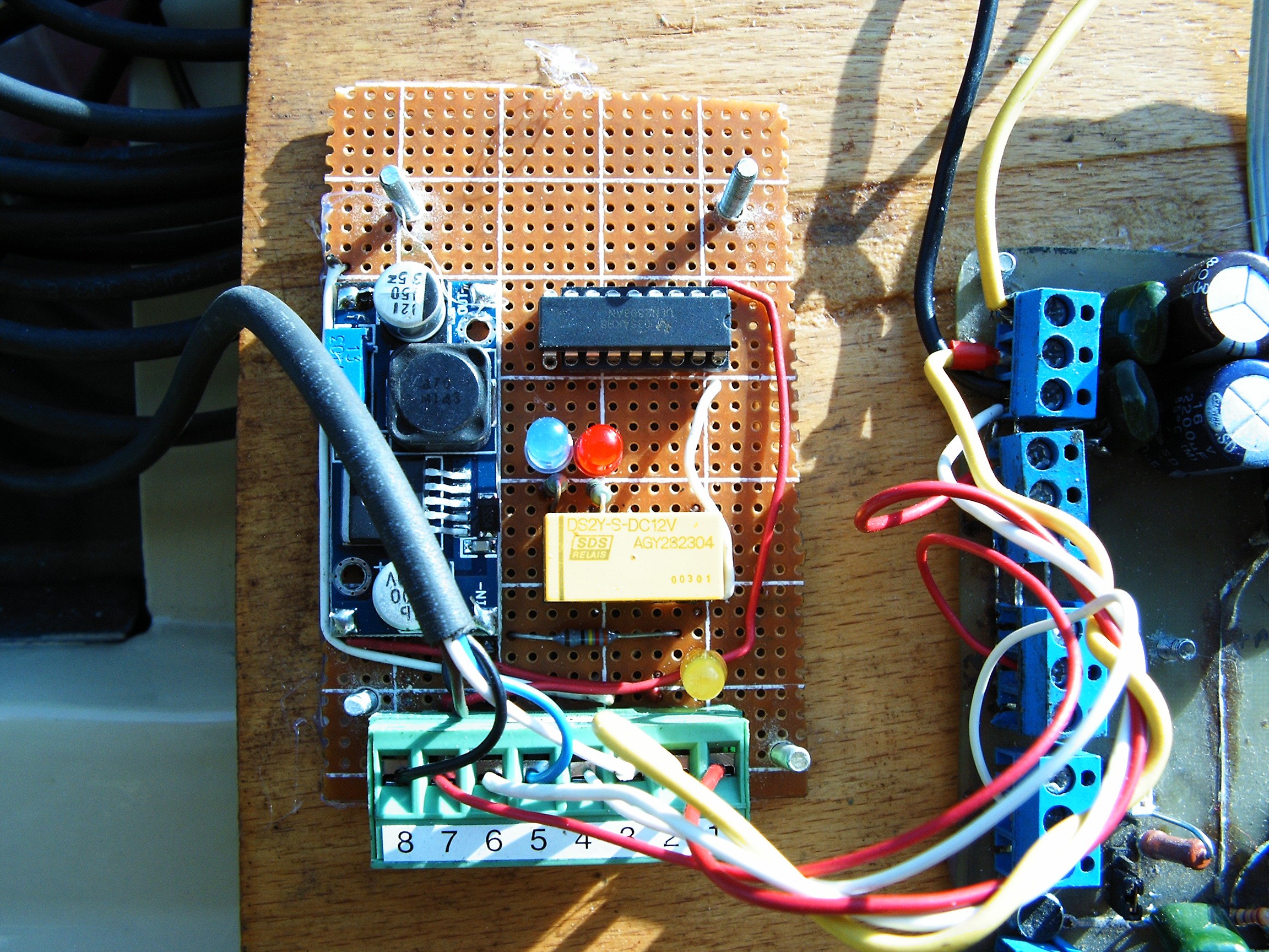 Connected here: pin3 = 3.3V, pin5 = VibraIn, pin8 = GND.
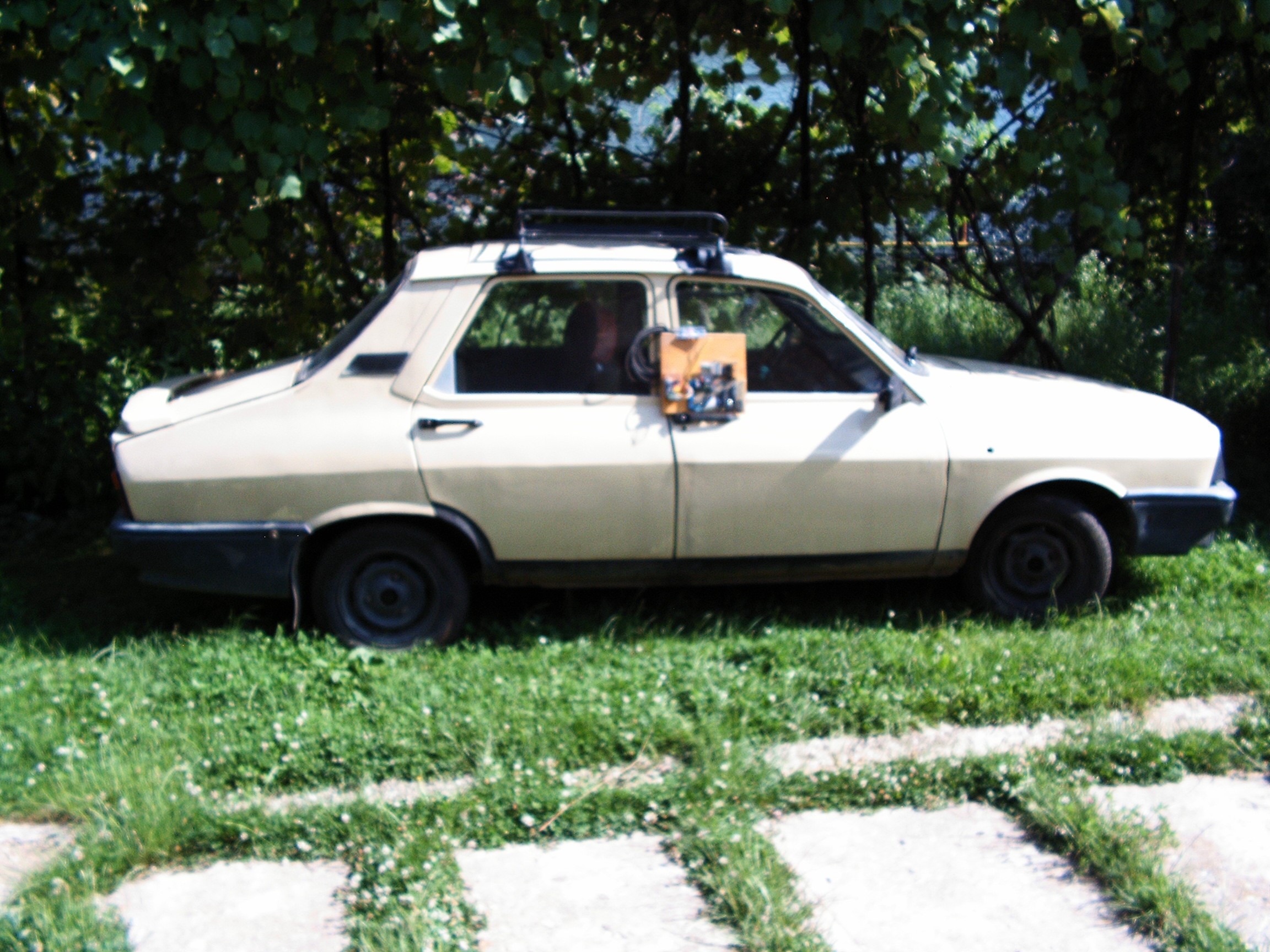
At this time I am forbidden to do this operation. It's too extremely hot today and she does not want me to risk my health and leave the house. I have to stay inside, locked in jail all day long. Maybe tomorrow when storms will start again AND I WILL FIND CHICKEN IN THE CAR - AGAIN!!!!! They come through the hole under the pedals to hide inside over night.
I won't install the sensor until I see the spectrograms flowing on screen displaying the vibration data, just like in the old times.
In the mean time - first experiments:

ADXL installed between alternator and engine block. Cable goes to "Blonde-Powered" ANN as described above. In parallel, the signal line goes to an USB sound card, microphone input.
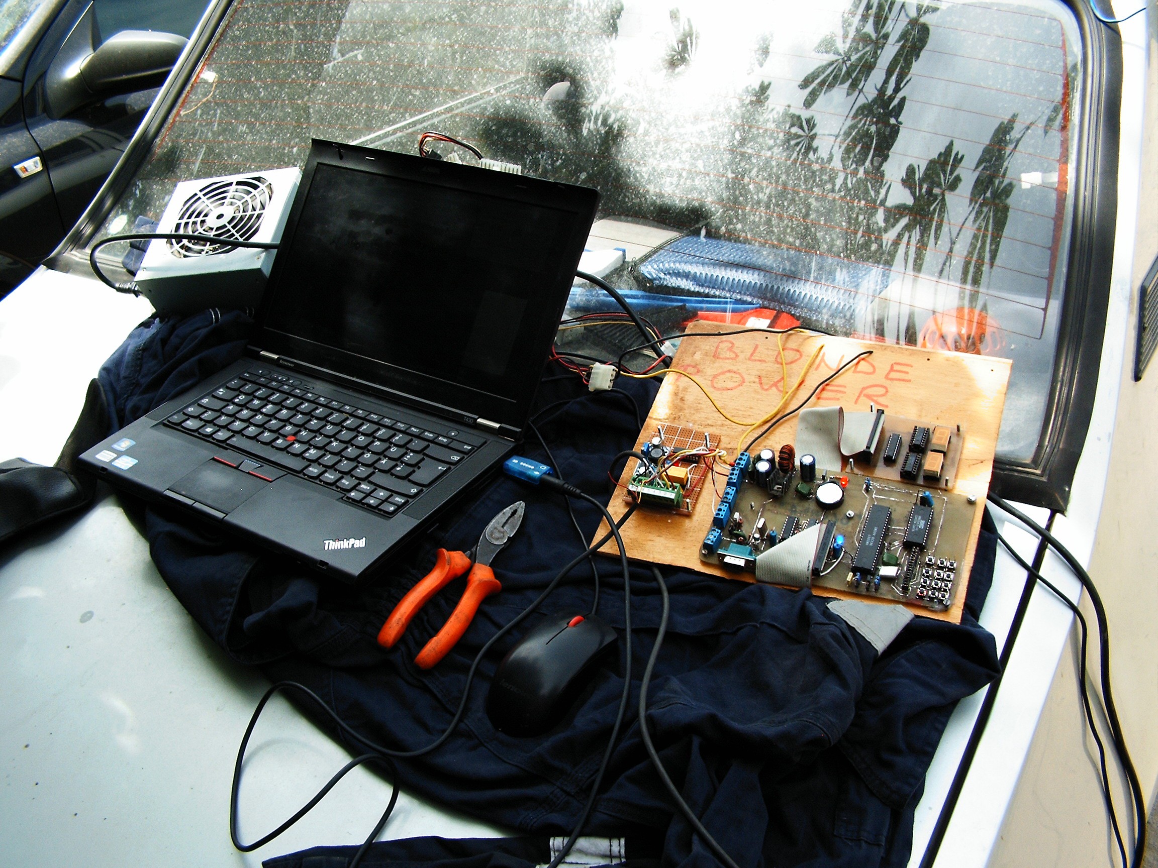
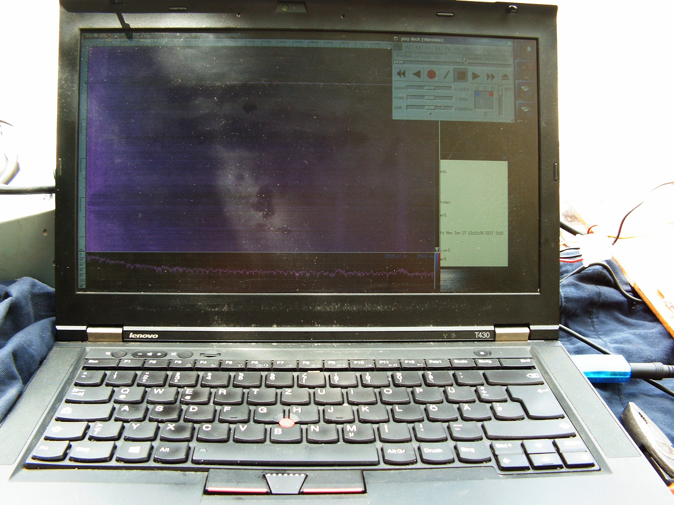
Laptop running Unix FreeBSD 11.0-ALPHA5, with Baudline for monitoring and Gimp Toolkit for screenshots.
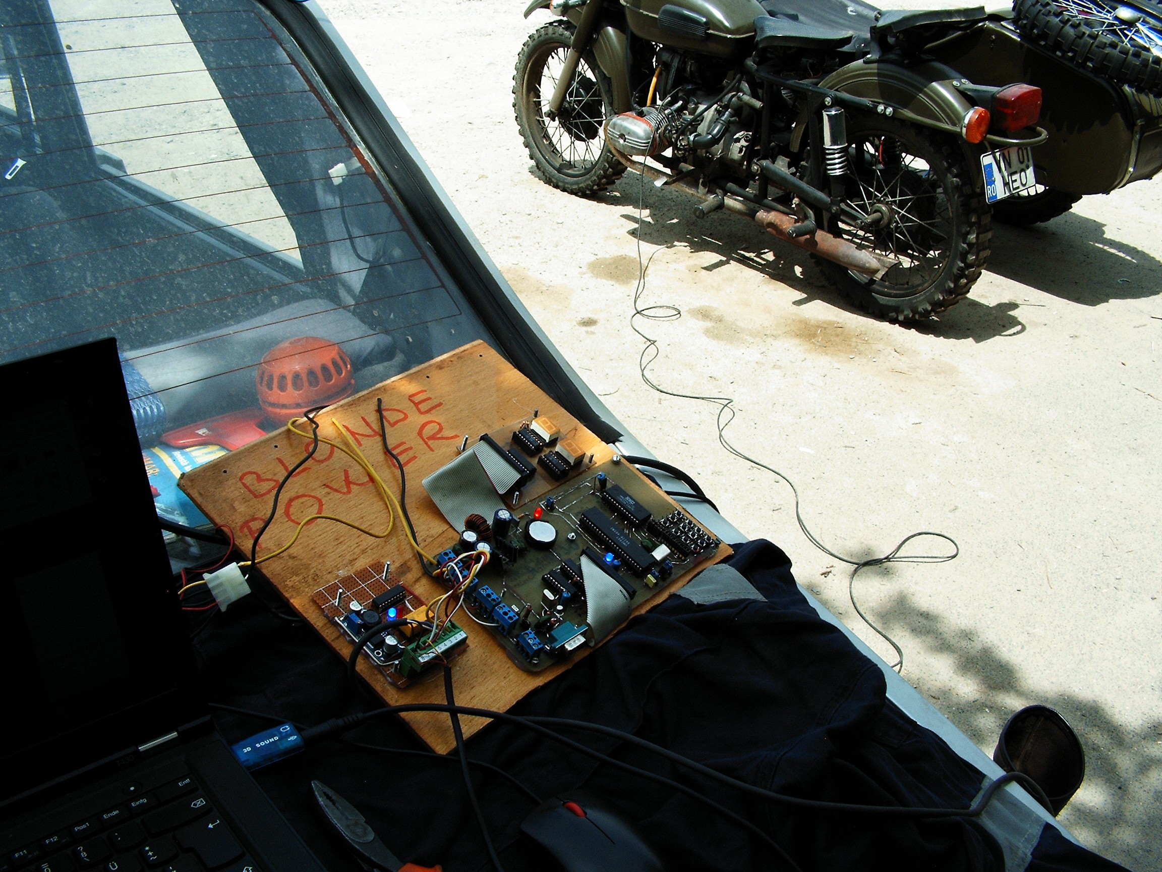
This is the system, and here is the audio data I gathered from the accelerometer while running the motorcycle engine.
In the mean time, in-house testing:
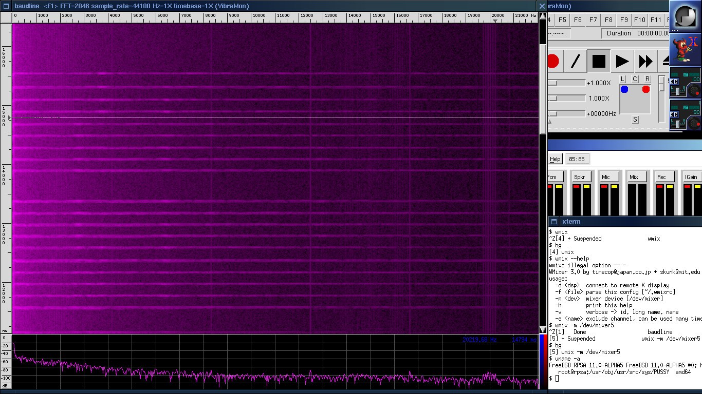 Accelerometer knocked with a knife:
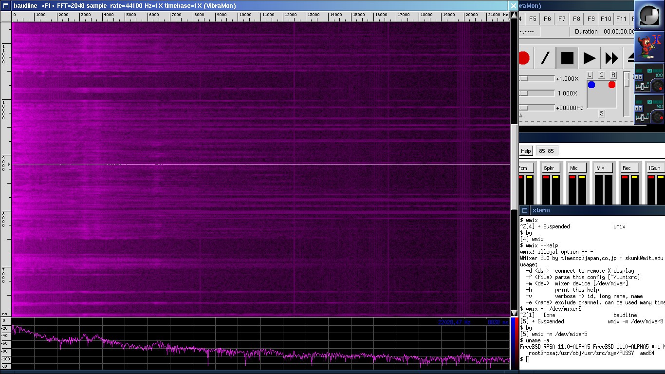
Accelerometer scratched with a knife:
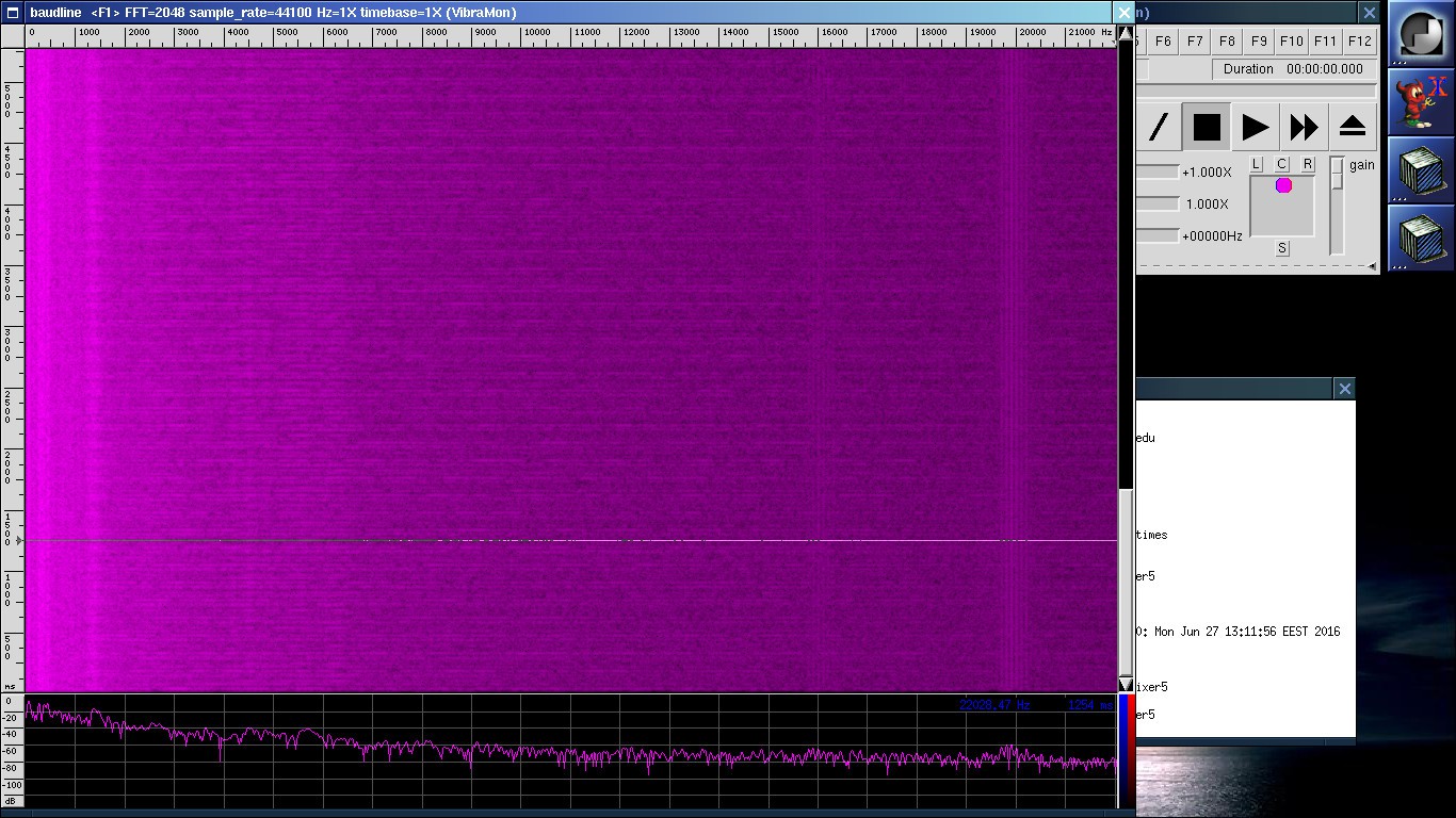
Spectrogram - ADXL accelerometer sitting on the left cylinder head where vibrations are the most horrible.
Also there's some constant noise in the upper spectrum. I hope it's the USB card reaction to the WiFi signals in that area.
You may notice that the mp3 contains distorted sound. While sitting on the rear axle, the vibrations won't be so terrible as this case. We'll see. That's why I need measuring devices, especially this wonderful tool called 'baudline'.
Accelerometer was installed behind the rear-left wheel mechanics.
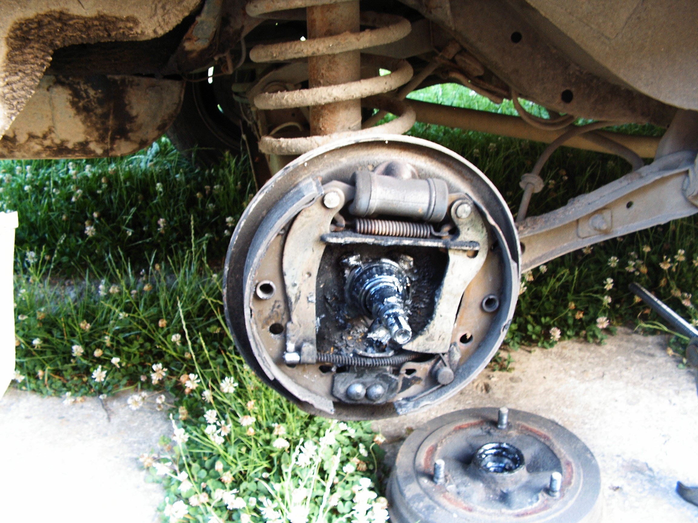
First - cover removed.
Behind the left-side brake plate there are some holes....
 That's it. Here we go.
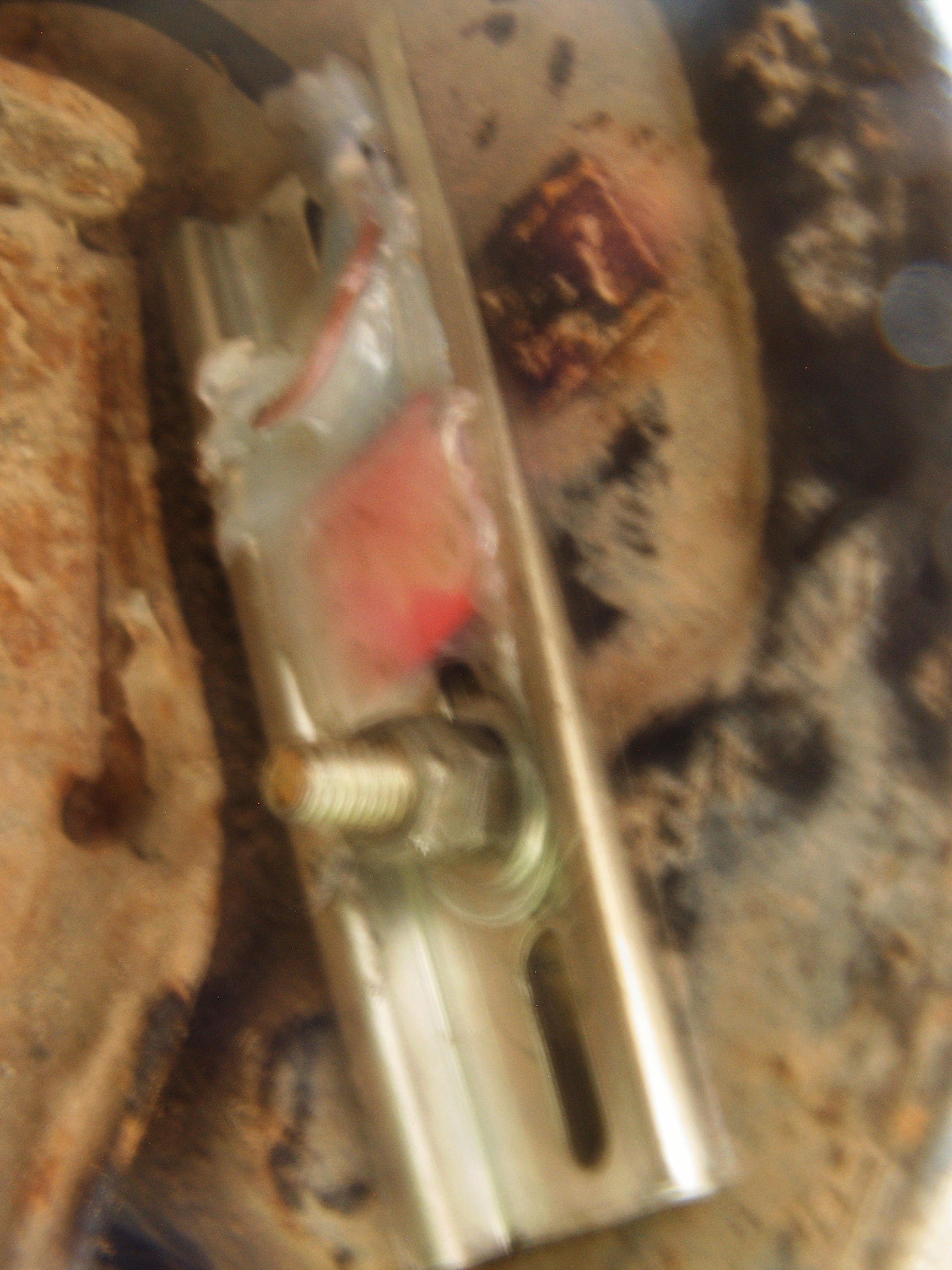

Storm is coming, need to move fast. Everything fixed in position.
Modern cars are tested for bad inside sealing using modern tech, such as controlled air/water jets, fumes and sensors. If something leaks inside the car, the project is remade.
However, Dacia tests were performed much simpler by using cats. Engineers locked a cat inside the car and left it in the sun. Wherever they could see the cat's head coming out, they marked the place and covered the hole with fiber glass.
In my case there are still a lot of holes left so it's easy to bring the sensor cable inside.
Now - tests.
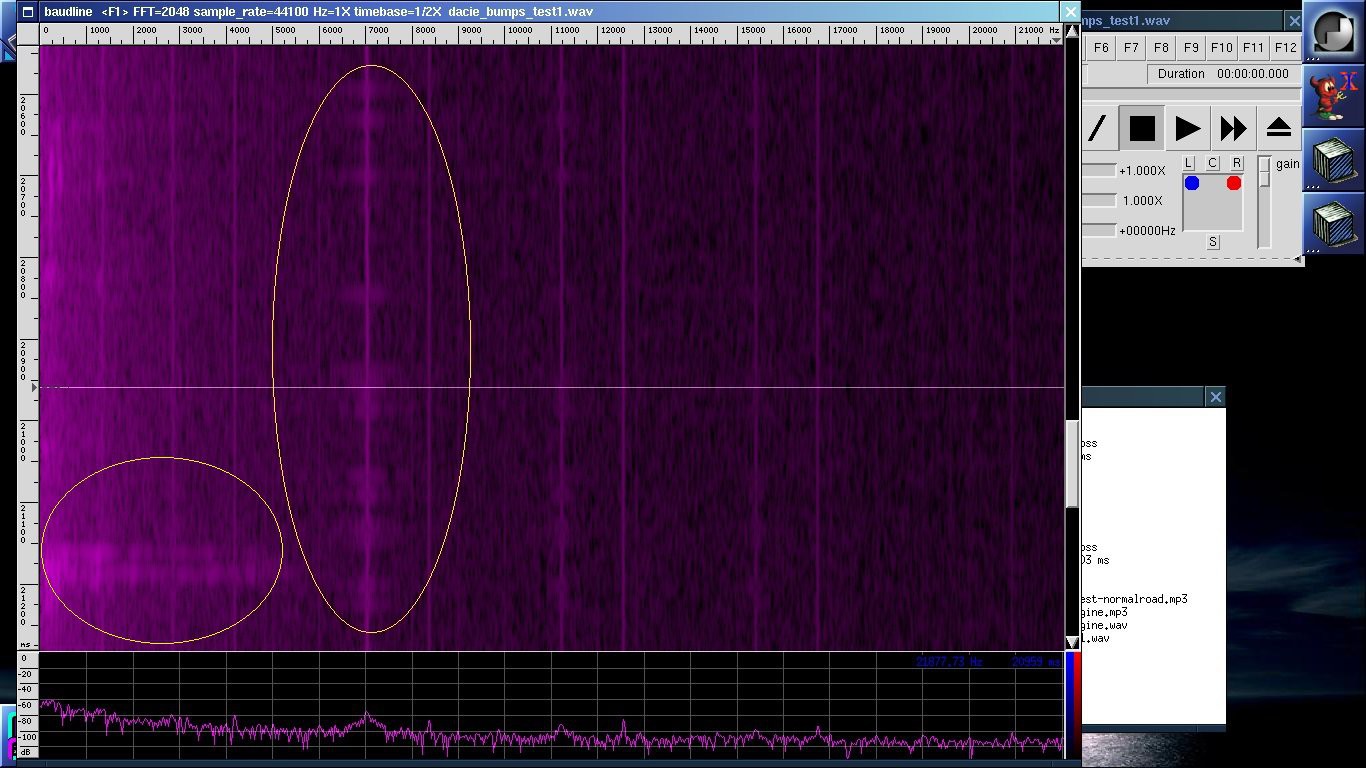
First - driving on a bad road with a lot of bumps. File is in MP3 format, if you plan to use baudline, you must also install mpg123.
Here's a screenshot:
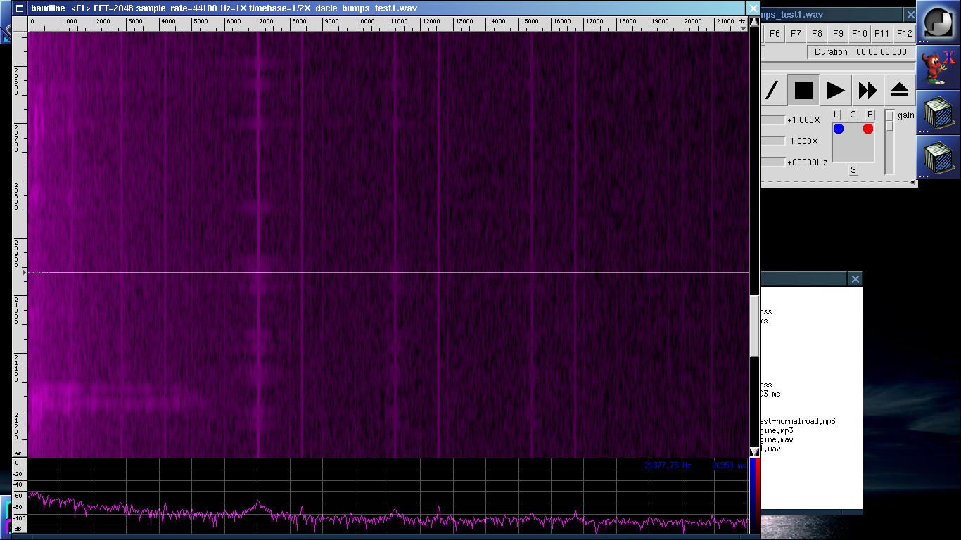
Another recording - normal road driving. At high volume at the end of recording you will be able to hear the brake scratching.
[END OF TRANSMISSION]
______________________________________
kernel panic: improbability coefficient below zero
 [skaarj]
Discussions
Become a Hackaday.io Member
Create an account to leave a comment. Already have an account? Log In.