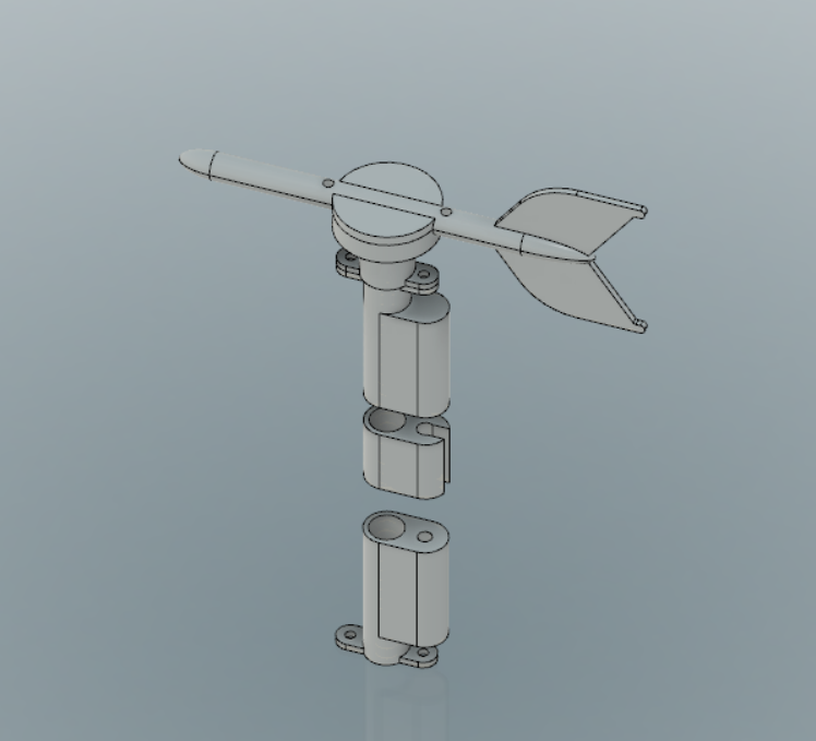
I've designed with autodesk fusion 360 the anemometer that I would like to use. It is attached to the mast. It is composed by two main hardware parts:
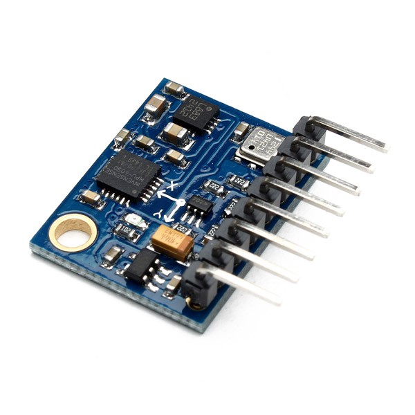
- The GY-87 IMU

- the 12.4mm 300Rpm 6 Wires 6 Conductors Capsule Slip Ring 240V AC for Monitor Robotic SRC012C

I didn't know about the existence of the second one, it is a very useful piece that allows to connect electric wires from two rotating components.
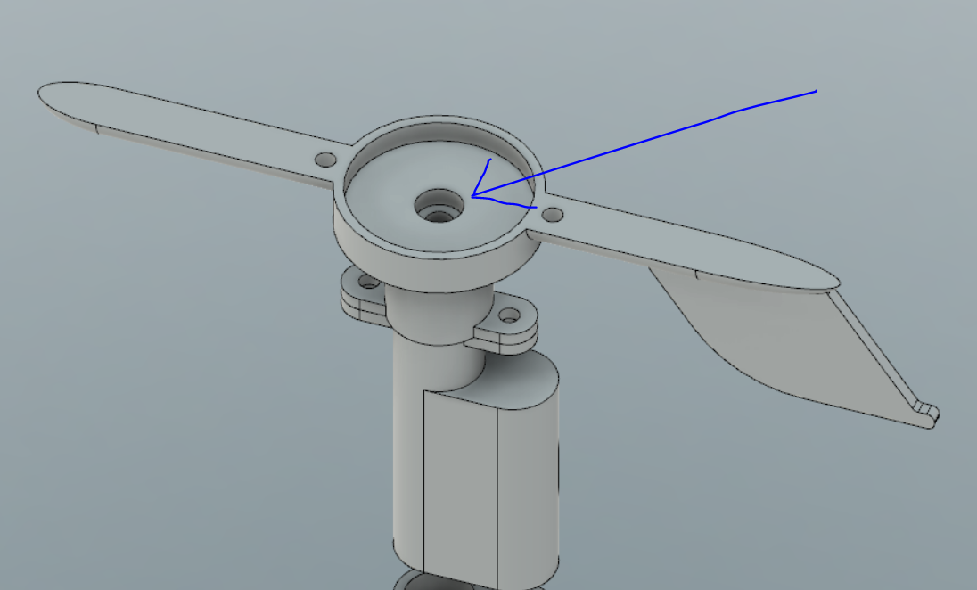
Both of them can be purchased for a few dollars on the web. The IMU will provide the wind heading and is placed in the anemometer rotating part:
while the second one will be placed between the rotating part of the anemometer and the base.
Here's the page with the STL files:
http://www.thingiverse.com/thing:1916259
I'm wondering if to add a dc motor a the front extremity of the "arrow" in order to get some more electricity, probably in the next log I will add it :)
 silvio biasiol

Discussions
Become a Hackaday.io Member
Create an account to leave a comment. Already have an account? Log In.