 Tobias
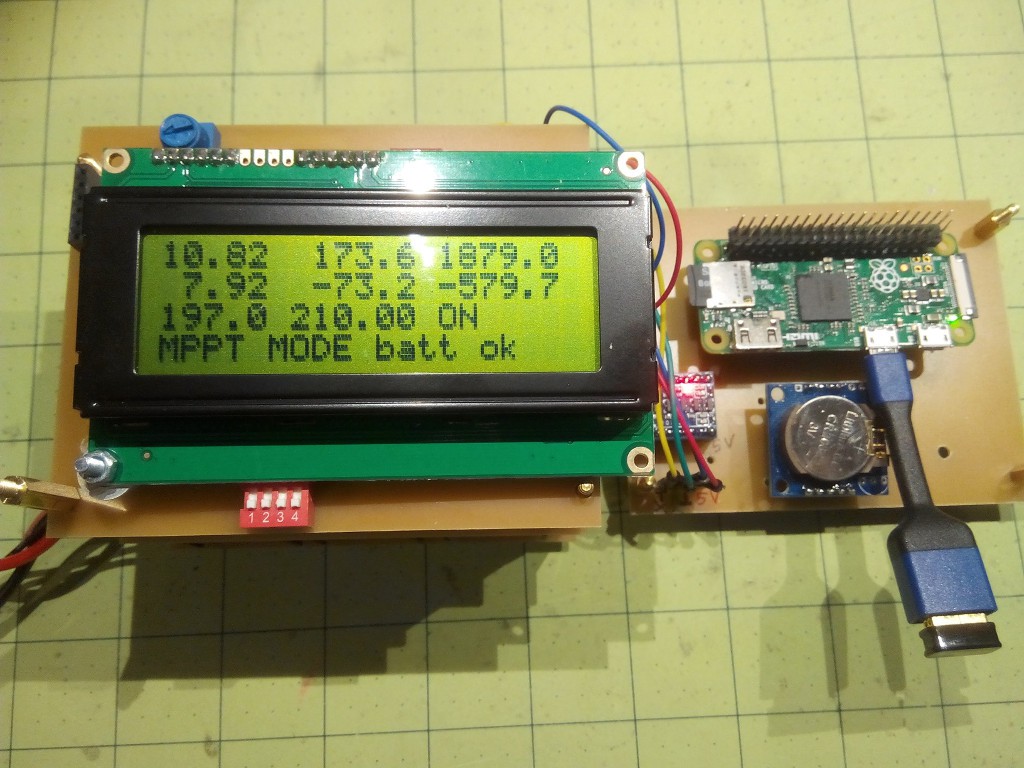
Now that I have a data logger, I can monitor the charge controller behavior. The first test is to make sure that the battery does not get charged beyond the 8.4 Volts, meaning that the PWM should lower the pulse width once the battery is full. In the chart, 100% pulse width is equivalent to the number 255 (one byte.) My algorithm in the Arduino first determines a target pulse width and then changes the actual pulse width by a small amount in each loop cycle. This smoothes out the PWM changes.

Discussions
Become a Hackaday.io Member
Create an account to leave a comment. Already have an account? Log In.