 Tobias
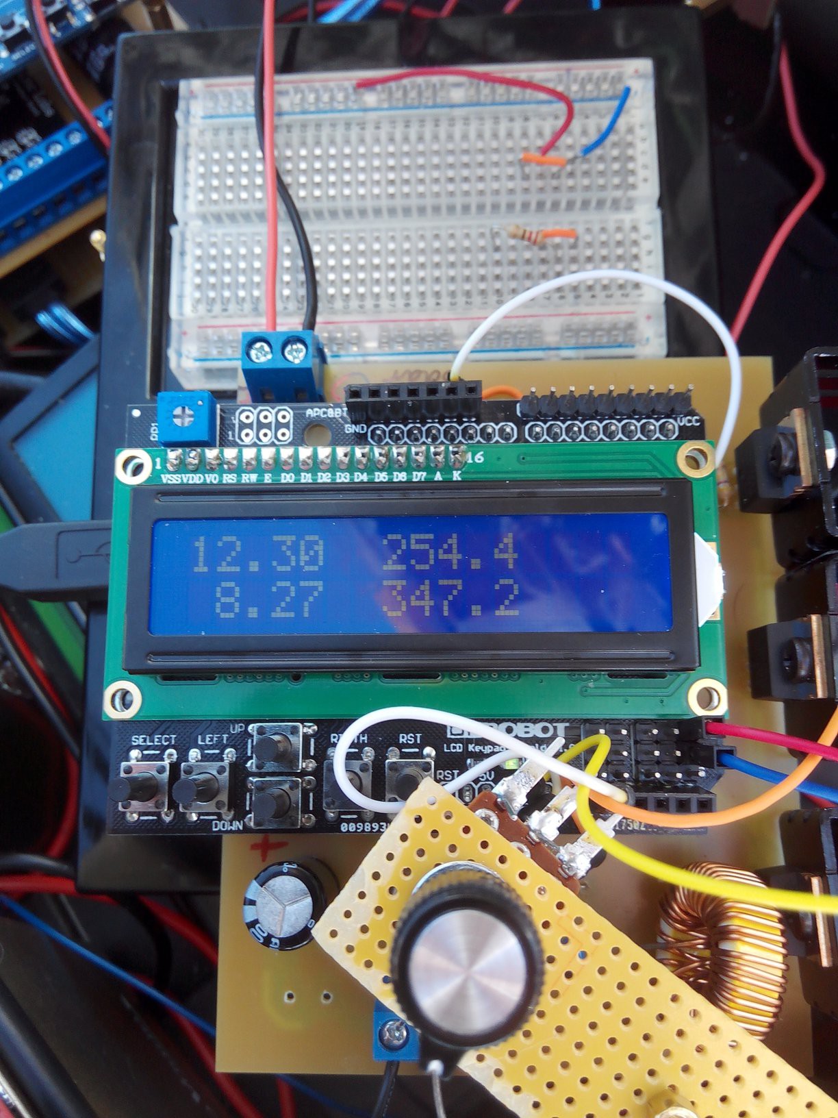
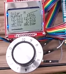
An LCD display was added to display the voltage and current on the input as well as the output. Later, I want to change the shield to an I2C shield and the display to a transflective (sunlight readable) 20 by 4 display so I can also show power, PWM, and efficiency. Also, a potentiometer was added to change the duty cycle of the PWM to conveniently find the maximum power point. It's a good step to test the system before letting the Arduino control the PWM. Credits to Julian Ilett for the idea.
Discussions
Become a Hackaday.io Member
Create an account to leave a comment. Already have an account? Log In.