 Adrian
With the initial design, the power supply was just 4xAA feeding the PIC + motor bridge etc. The idea was to eliminate the need for a regulator as the batteries could be expected to be between 1.6V max and 1.1V min. and by introducing a silicon diode in series with the battery supply, we get battery reversal protection and a 0.7V drop to keep Vdd within safe limits. This worked fine with fresh batteries but after around one weeks use the gantry motor didn't get enough power to lift two wet teabags.
The volt-drops were all adding up: e.g. 1.3V at each AA minus 0.7V diode drop meant only 4.5V was feeding the Vdd rail. 0.2V in the PNP side of the H-Bridge plus another 0.4V lost in the steel battery springs (has anyone else noticed how resistive these things are?) all conspiring to make the motor stall out.
Handily, I've acquired a few tubes of LT1371 Boost converters so the solution was to boost the battery supply up to a regulated 6V and regulate the 5V for the PIC with a Linear LDO. This was all made using SM parts soldered on the back of the stripboard:
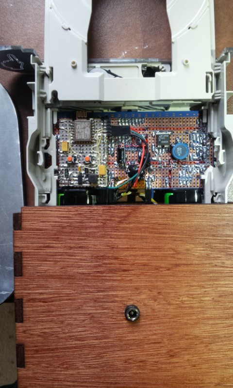
Top right: SM LT1371 legs splayed out to match 0.1" stripboard - works for me.
Top left: ESP8266 add to provide IoT capabilities - naturally.
Discussions
Become a Hackaday.io Member
Create an account to leave a comment. Already have an account? Log In.