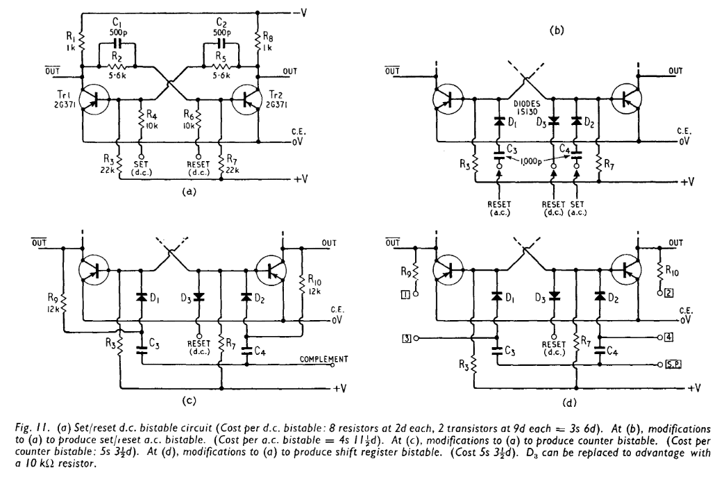
I still feel that the divide-by-two diagram in the "details" page is messy.
I tried to address this (rather critical) issue in Easier frequency division but the principle is not reliable enough.
I just stumbled on a better laid out circuit at http://www.smrcc.org.uk/members/g4ugm/Manuals/wirelessworldcomputer.pdf

The old (1968?) book also explains how the whole thing works.
I faintly remember seeing this sort of circuit in one of @Shaos's russian books but 1) I don't read russian 2) the circuit was pretty messy too...
I'm concerned that the OC70 might not be fast enough to work at 18KHz so I must find a more reliable (ECL-based ?) method for the first stages of the predivider.
I'm puzzled by the circuits of that time : they use 3 power rails (-Vcc, 0V and +Vcc). +Vcc seems to be used only as a "pull-up", maybe to accelerate charge dissipation and recover from saturation. I'll have to substitute with Germanium diodes for Baker clamps...
Now, considering that a ECL latch uses about 7 transistors (a DFF uses 14), the predivider would be too expensive with this approach. However, the circuits close to the resonator will work close to the maximum speed of the transistors...
 Yann Guidon / YGDES
Discussions
Become a Hackaday.io Member
Create an account to leave a comment. Already have an account? Log In.