Close
0%
0%

OpenFence - Digital Livestock Fencing

OpenFence is an open source GPS based digital livestock fencing system and web interface, aiming to reduce barriers of using cell grazing.

Similar projects worth following
OpenFence is an open source digital livestock fencing system, which uses GPS and a combination of alerts (stereo speakers and electric shock) to contain animals within a specified boundary. The location of the fences can be updated using a web interface, and transferred to collar devices via a repeater station. The movements of the animals is also logged and transferred to the web to allow analysis of movements and land utilisation.

OpenFence is designed to make it easier to implement productive and environmentally friendly grazing practises, such as cell grazing. Cell grazing involves splitting a property into many small paddocks (requiring more fencing than common continuous grazing), moving animals frequently (every few days), and allowing that cell to rest for an extended period. This style of grazing has been shown to increase biodiversity, ground cover and water retention, however it is not as commonly implemented due to the additional expenses of fencing and labour.

Background

Cell grazing changes the focus of a grazing farm operation from raising animals to managing grasslands. The health of the land must be the priority, as in poor conditions productivity of the farm will be reduced. The most common style of grazing is continuous, where animals are left in an area for long periods of time, often the entire year and eat the grass as it begins to grow back. This results in more stress on the plant and hampered regrowth, eventually resulting in a loss of biodiversity of grasses.

Cell grazing is a time-control grazing method, however it differs from other time-control techniques such as block or strip grazing in that it has a holistic focus. The focus of cell grazing is on sustainability and optimising profit, rather than on maximising plant and animal growth. Holistic management is a whole farm planning method with the aim to deliver successfully on the triple bottom line, sustainable environmental, economic and social outcomes. Cell grazing essentially aims to maximise the harvest of sunlight, by implementing the following principals [1]:

  • Control rest to suit the growth rate of the plant
  • Adjust stocking rate to suit match carrying capacity
  • Plan, monitor and manage the grazing
  • Use short graze periods to increase animal performance
  • Use maximum stock density for the minimum time
  • Use diversity of plants and animals to improve ecological health
  • Use large mob sizes to encourage herding

With the goal to [1]:

  • Improve the biodiversity of the soil
  • Increase the carbon in the soil, through the creation of topsoil
  • Increase the drought tolerance of the grassland, through deeper roots and better water holding ability
  • Increase animal productivity and health

Pioneers such as Allan Savory have been advocating the benefits of holistic management, and educating others on its implementation for over 50 years. He believes that desertification of land can be reversed by running more livestock, rather than the conventional response to run less or completely remove the animals and rest the land. This does not prepare the land for recovery though; when it rains the water simply runs off the dry bare land. If livestock are used correctly they can have a beneficial effect as they create many small divots in the ground, where water can soak in, and fertilise the soil with their dung.

There are many examples of people using this type of holistic management on their land and seeing real improvements. Almost all of the graziers who have won Australian Farmers of the Year awards since 2007 have described cell grazing as the core of their farm plan [2]. As an example, in a low rainfall area of South Australia, one grazier has gone from a ground cover of less than 50% to 70-80% in just 7 years of using cell grazing [3]. This increased ground cover means that with only 10mm of rain the paddocks produce feed, when previously the water just ran away. For scientific analysis of cell grazing see T. McCosker’s report [1].

Soil is the third largest sink of carbon in existence, after oceans and geologic sinks [4], so increasing the amount of carbon in the soil could present a safe and simple way to sequester carbon. Many of our modern farming practises are having the opposite effect of losing soil carbon, which reduces the productivity of the land, requiring more inputs to maintain fertility. The most effective way to increase the amount of soil carbon is to ensure that there is plant growth in the soil at all times [4]. Perennial grasses with good coverage and animals that are involved in the grasses life cycle have the potential to take carbon out of the air and store it in the soil.

The factors that make cell grazing a less attractive option than continuous grazing are, access to water, more fencing and increased time spent herding animals. Through smart layout of the cells it is possible to reduce the number of watering points required. The cost of fencing these additional smaller paddocks is significant, and therefore a major drawback...

Read more »

  • Final Report and Video

    Alex Muir11/10/2016 at 11:15 0 comments

    So the project is technically finished, in that I've submitted all my documentation and my time at university has come to an end.

    Here is the video and technical report for those who are interested!

    OpenFence Final Report (12mb PDF)

  • Nearing Completion of the Project

    Alex Muir10/09/2016 at 22:24 0 comments

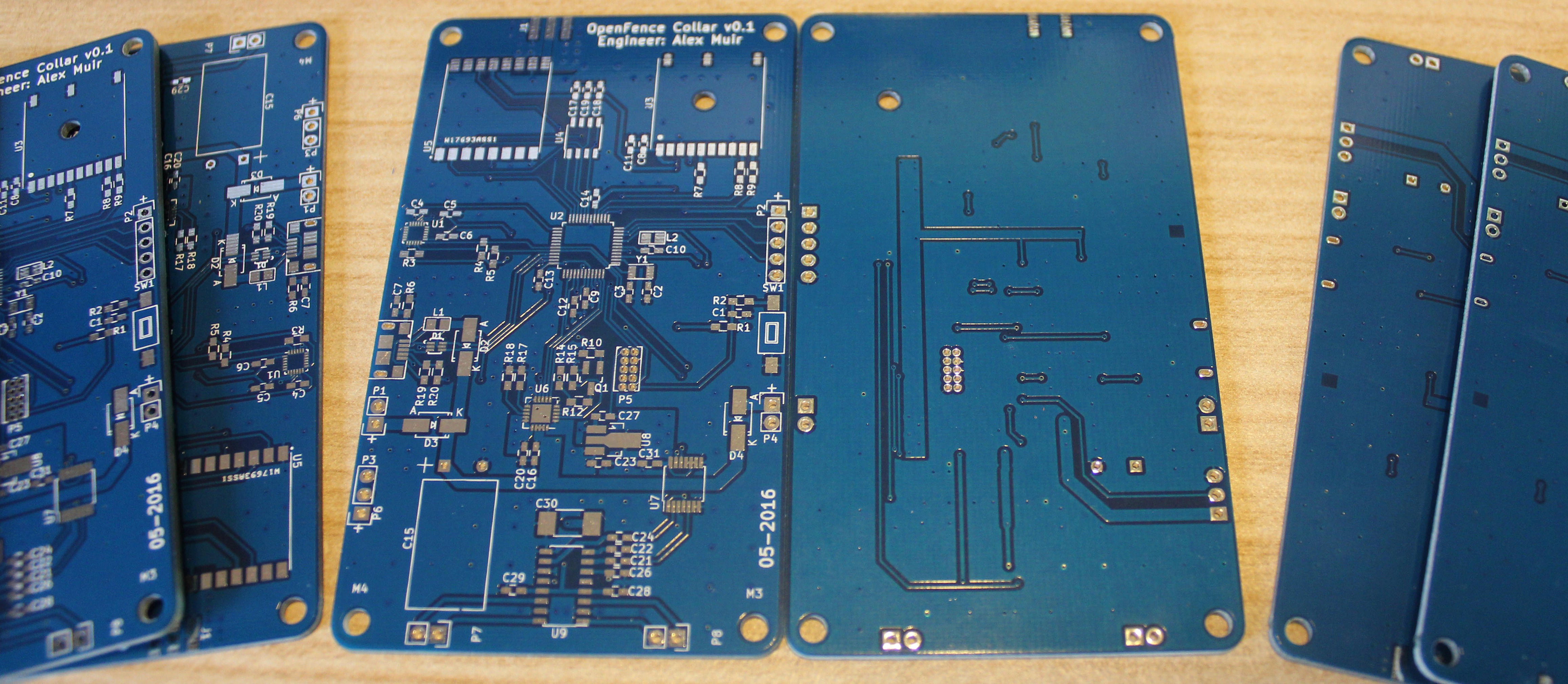
    Four copies of the collar board have been put together. Only really three errors in the board design: micro USB pin spacing isn't quite the same as the footprint, regulator footprint had Vin and Vout switched, changed my mind about using the DAC for audio output (using a PWM output now).

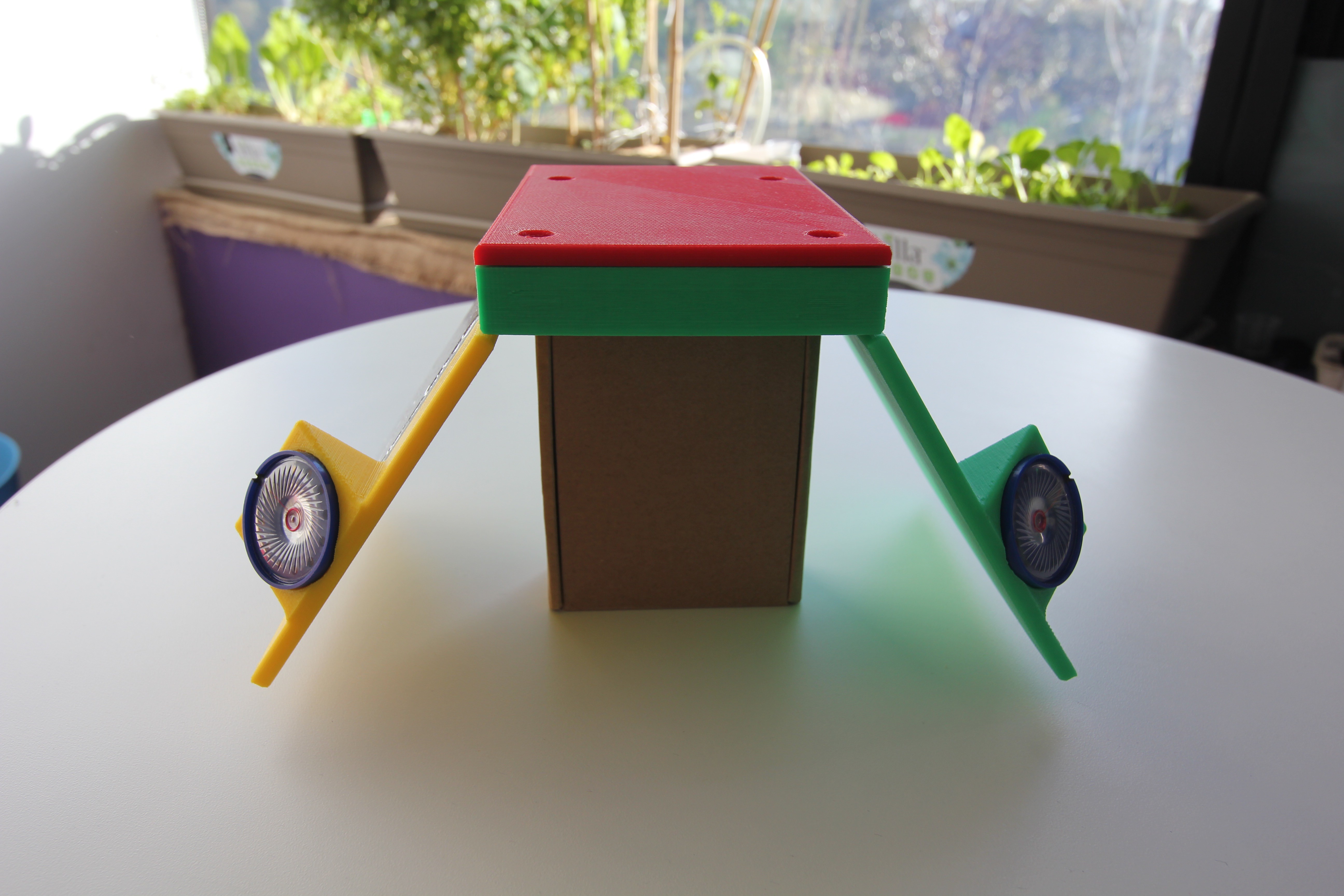
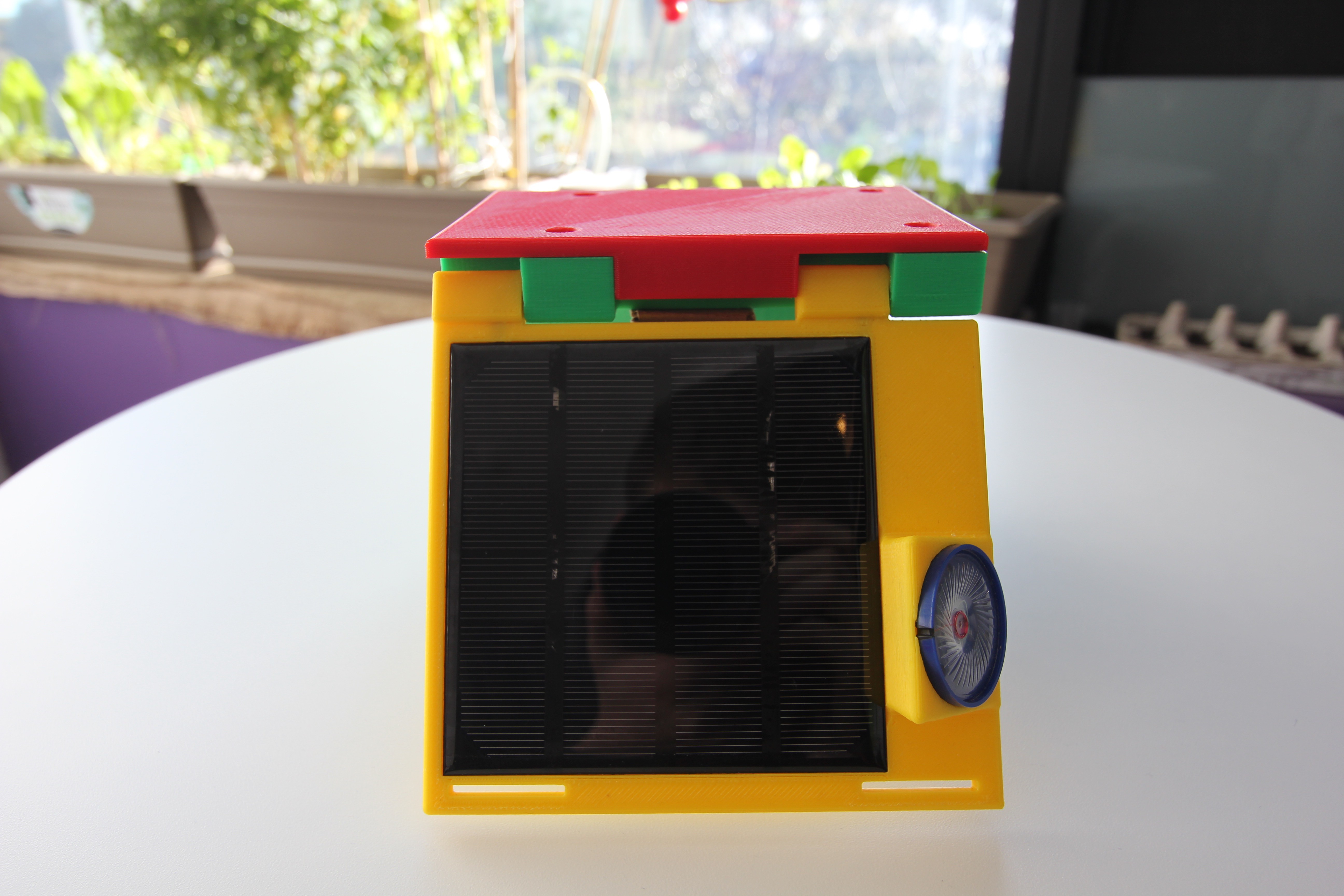
    Was able to try it on a cow a week ago. Safe to say it was a very interesting experience! Collar design isn't ideal, being top heavy it rotated upside down as she moved around, and it doesn't fit the shape of the neck particularly well. I would definitely redesign the enclosure to not have the square top and to have the majority of the weight at the bottom of the collar (was my original plan).

  • Initial Web Interface

    Alex Muir08/13/2016 at 23:58 0 comments

    A major task that was completed over the mid year break was to develop the web interface that will allow the easy placement of fences, and to track the movements of the animals.

    It is built on the MEAN stack, utilising NodeJS, Express, Angular and MongoDB. Having not used this before (or really knowing JavaScript) there was a fair bit of a learning curve, and I'm sure that it hasn't been implemented perfectly in terms of following the principles of RESTful websites!

    So far I've only implemented the two important pages that allow the placement of fences and viewing of logged points. I'll continue to improve it over the next two months, as well as creating the other pages to allow updating website and collar settings and viewing statistics.

  • 3D Printed Enclosure

    Alex Muir08/13/2016 at 23:40 0 comments

    Haven't updated this for a while so here comes a whole bunch of posts in a row!

    An initial prototype of the enclosure has been printed. Whilst everything works fine with the enclosure, I'm not sure that it is ideal for actual use, it seems quite bulky, and the hinge would likely not be strong enough for actual use. Possible changes to the design would be to remove the centre section, and have one side contain the PCB and the other side the battery. Will look into this over the next few weeks, however I have limited time before the project is due to be completed and since most of my marks will be for the electrical and software design it will be a lower priority.

    1. Wireless Communications

      Alex Muir06/27/2016 at 07:33 0 comments

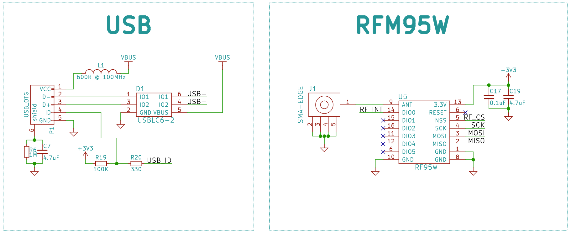
      An important feature of the OpenFence system is the ability to update the fence position remotely and to be able to track the animals’ movements over the day. This requires some sort of wireless communication. As was mentioned in the component selection above, LoRa has been chosen for the physical layer of the system. The HopeRF RFM95W is a 915MHz module, which has the ability to transmit over long distances with low power consumption, and is available in relatively cheap modules.

      The network will use a star topology with the collar nodes only looking to receive packets after they complete a transmission. This will reduce the power consumption significantly by not having the module always looking to receive data. The star topology was chosen over the option of a mesh network, as it would require the collar nodes to be always receiving and then sometimes retransmitting messages, consuming much more energy. Another flaw with using a mesh network for this application is that the position of the animals will be constantly changing, making it difficult for the network to find the most efficient path to a particular end node.

      The “RadioHead” library (GNU GPLv2) is available for the RFM95W that is being used for this project. This library provides the ability to transmit and receive reliable (acknowledged) packets to up to 255 nodes as standard, with the possibility of altering this to allow more node IDs. It supports broadcasting to all nodes, and has the ability to classify messages into 16 different categories using 4 bits of flags in the header. The complete message format is shown below.

      Currently there are two types of messages that are being sent between the base station and collar. The first is a position update from the collar to the base station and contains the location, time, date and number of alerts and shocks so far today. The second is a fence update from the base station to the collar and contains the fence version, number of corners, and the positions of these corners. Both of these two packets are 20bytes as can be seen in below.

    2. PCB Manufacture!

      Alex Muir05/26/2016 at 06:21 0 comments

      After completing the PCB design I sent off the Gerbers to PCBWay for manufacturing, a week later they are here! The quality is excellent for the price and the service was really easy to use.

      Components are starting to arrive. Soldering the components will be started once I have them all.

      Software has been progressing with LoRa communications working well (next post will be on that).

    3. PCB Design

      Alex Muir05/19/2016 at 05:59 0 comments

      PCB has been laid out in KiCAD, Gerbers generated and sent for manufacturing. The following are renders of the front and back from GerbLook. It is a two layer design, with a board size of 97mm x 57mm.

      The design has tried to minimise opportunities for noise and interference. The high frequency components are towards the top, digital and power circuitry in the middle, and audio at the bottom.

      To ensure the antenna output was matched to 50 Ohms, Saturn PCB Toolkit was used to design the coplanar waveguide. 50 mil with an 8 mil gap to the surrounding ground plane on 1 ounce copper was determined to provide 50 Ohm impedance.

      Wasn't quite as impressed with KiCAD's PCB design tool, not being able to easily stitch the ground planes together and not being able to drag tracks were the biggest peeves. Still for a completely free program it does a good job!

      As always if you want to look at the original Gerbers or KiCAD files they are available on GitHub.

    4. Schematics

      Alex Muir05/10/2016 at 11:34 0 comments

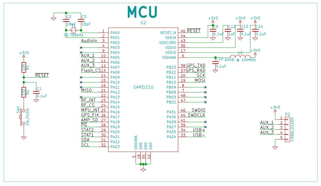
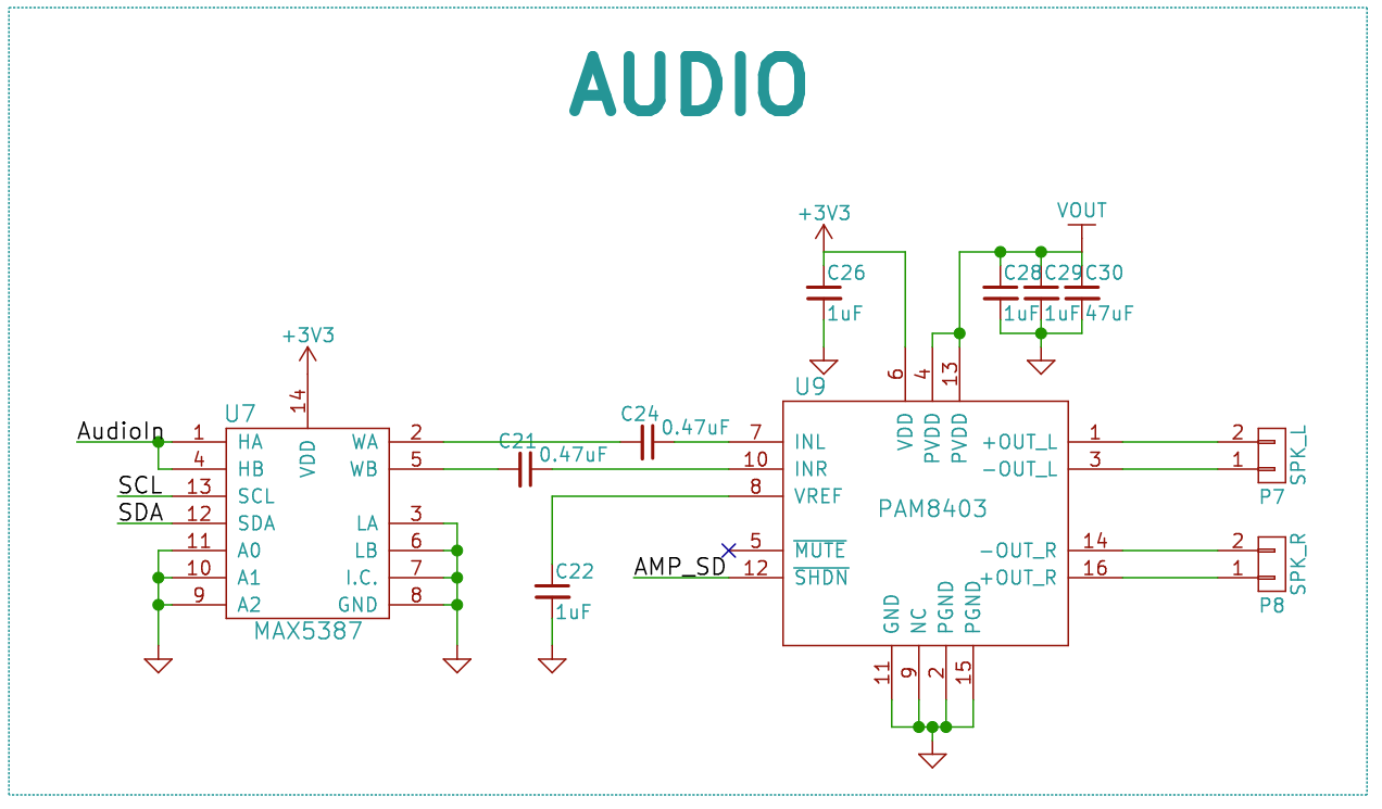
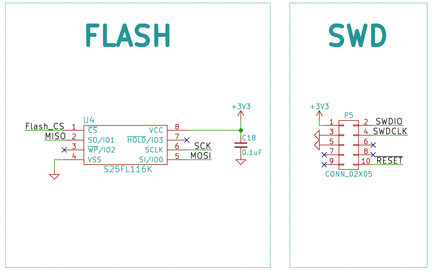
      Schematics have been basically finalised, although check the GitHub one for the most up to date version. I have been using KiCAD for this project, having moved from designing in Altium for another project over the summer. Really impressed with the functionality and keyboard shortcuts of KiCAD, everything is just what you expect it to be.

      Most of the circuits are based off each devices application circuit, along with comparisons to the breakout boards I have for many of them. If you have any feedback or questions, pleasedon't hesitate to comment!

      MCU

      Power Management

      RF and USB

      Audio

      GPS and IMU

      Flash and SWD

    5. Component Selection

      Alex Muir05/05/2016 at 22:57 0 comments

      So after many weeks of ordering and testing components, I have almost finished selecting the major components I will be using (at least for my first version). Here I will layout some of the comparisons of components that has led me to the selections in the hope that it might help others deciding between components for their project and provide the thought process behind my choices.

      MCU

      I have chosen to use the Atmel SAM D21 as the microcontroller as it is a low power chip that will provide enough processing power for this project. I have worked with this chip before so the development will be easier than moving to another manufacturer.

      GPS

      Global Top

      PA6C

      uBlox

      NEO M8M

      SkyTraq

      S1216F8-GL

      Antenova

      M10478-A1

      Chipset

      MTK MT3339

      UBX-M8030

      SkyTraq Venus 8

      SiRFstarIV

      Current

      Acquisition

      Tracking

      25mA

      20mA

      24.5mA

      23.5mA

      45mA

      40mA

      47mA

      31mA

      Interface

      UART

      UART, I2C, SPI

      UART, I2C

      UART, I2C, SPI

      Input Voltages

      3.0V to 4.3V

      Ripple <50mVpp

      1.65 to 3.6V

      3.0V to 3.6V

      1.8V

      Acquisition Time

      Cold: 35sec

      Warm: 33sec

      Hot: 1sec

      Cold: 27sec

      Warm: 4sec

      Cold: 29sec

      Warm: 3.5sec

      Hot: 1sec

      Cold: 35sec

      Warm: 35sec

      Signal Sensitivity

      -165dBm

      -164dB

      -165dBm

      -147dB

      Position Accuracy

      3.0m

      2.5m

      2.5m

      2.5m

      Update rate

      Up to 10 Hz

      Up to 10Hz

      Up to 20Hz

      1Hz

      Additional Features

      Includes antenna

      Concurrent GLONASS and GPS

      Concurrent GLONASS and GPS

      Cost

      $16

      $59

      $16.20

      $22

      I have selected the Global Top PA6C due to it's low cost, low current draw, and ease of implementation.

      Communications Chipset

      NXP KW40Z

      TI CC2650

      TI CC1310

      X-Bee Pro 900HP

      RFM95W

      Protocols

      BLE

      ZigBee

      Thread

      BLE

      ZigBee

      802.15.4

      802.15.4

      ZigBee

      LoRa

      GFSK

      Frequency

      2.4GHz

      2.4GHz

      900MHz

      900MHz

      900MHz

      Throughput

      250kbps

      250Kbps

      50Kbps

      200Kbps

      10Kbps

      Typical Receiver Sensitivity

      BLE: -91 dBm

      (802.15.4): -102 dBm

      BLE: -97 dBm

      (802.15.4): -100 dBm

      -124dBm

      -100dBm

      -148dBm

      Core

      ARM Cortex M0+

      ARM Cortex M3

      ARM Cortex M3

      -

      -

      Memory

      160 KB Flash

      20 KB SRAM

      128 KB Flash

      28 KB SRAM

      128KB Flash

      28KB SRAM

      -

      -

      Power Consumption

      RX: 6.5 mA

      TX: 8.4 mA

      RX: 5.9 mA

      TX@0dBm: 6.1 mA

      TX@5dBm: 9.1 mA

      RX: 5.5mA

      TX@10dBm: 12.9mA

      RX: 80mA

      TX: 210mA

      RX: 10.4 mA

      TX:

      Range

      100m

      100m

      Several km

      6.5km

      8 km

      Cost

      $5.65

      $11.40

      $11.40

      $60

      $12

      For the communications chipset I am currently using a LoRa module, as I tried getting communications working with the TI CC2650 with the plan to move to the pin compatible CC1310 however I had a lot of difficulty getting them to work. So for my time constrained development I am using the HopeRF RFM95W as it has simple to use drivers available, is cheap and provides good range. I will definitely be looking into the CC1310 once the Launchpad development kit is released for it.

      IMU

      Invensense MPU9250

      Bosch BMX055

      STM LSM9DS0

      Features

      Accel/Gyro/Mag

      Accel/Gyro/Mag

      Accel/Gyro/Mag

      Input Voltage

      2.4 – 3.6V

      2.4 – 3.6V

      2.4 – 3.6V

      Current

      Accel

      450uA 4kHz (8.4uA 1Hz)

      120uA

      350uA (A+M) 50Hz

      Gyro

      3.2mA 1kHz

      5mA

      6.1mA

      Mag

      280uA 8Hz

      170uA 10Hz

      350uA (A+M) 6.25Hz

      Communications Protocol

      I2C/SPI

      I2C/SPI

      I2C/SPI

      Additional Components

      3

      2

      4

      Cost

      $4.20

      $9.25

      $9.50

      I need an 9DOF IMU for determining the rate of movement, compass heading and possibly dead reckoning. I have chosen the MPU9250 as it is a commonly used device, is available quite cheaply and has fairly comparable current draws to the others I looked at.

      Amplifier

      Linear - PAM8407

      TI - TPA2008D2

      Maxim - MAX98303

      Linear – PAM8403

      Class

      Class D

      Class D

      Class D

      Class D

      Input Voltage

      2.5 – 6.0V

      4.5 – 5.5V

      2.6 – 5.5V

      2.5 – 6.0V

      Quiescent Current

      8mA

      7mA

      2mA

      8mA

      Output Power

      2 x 3W (4Ohm, 5V)

      2 x 2.5W (4Ohm, 5V)

      2 x 3.1W (4Ohm,

      2 x 3W (4Ohm, 5V)

      ...
      Read more »

    6. Enclosure Design

      Alex Muir04/22/2016 at 23:51 0 comments

      I have spent a bit of time improving the design of the collar enclosure in Solidworks, so I can start 3D printing some test versions once I receive and measure the last few components (speakers and solar panels) that I am waiting on.

      In order to make the collar fit many sized animals I have made the two sides such that they can rotate up and down. This adds some difficulty in getting the wires from the solar panels, speakers, etc to the main circuit board and keeping it weatherproof. I have designed the hinge such that the wires can go through them, however this will require testing as to whether it reduces the strength of the pin significantly.

      There are still a few things to add, but for now I will keep working on the electronics with final component choices being made (next log) and PCB design to begin.

      Files are available at GitHub (GNU GPLv3).

    View all 12 project logs

    Enjoy this project?

    Share

    Discussions

    msjs08 wrote 05/28/2024 at 09:39 point

    It's  weird, electric fences are used everywhere and they seriously bite (mine sit between 4.5kV and 7.6kV yet in most of Australia, these collars are banned.. There is much pressure though, to change this. These collars give warning, my fence doesn't, not even to me when I make a mistake. :-(

      Are you sure? yes | no

    ian.alston wrote 05/04/2024 at 11:15 point

    Hi Alex, did you ever do any more with this project?

      Are you sure? yes | no

    Maxertje wrote 05/03/2017 at 13:32 point

    Hi Alex, I have an off topic question. You're not using an external 32k oscillator along with the SAMD21, which is standard configured in Arduino. On GitHub, you configured the internal 32k oscillator (OSCULP32K) In the sam-ba bootloader and the arduino core. Did you made some more changes for using the internal 32k oscillator? I can still measure power and frequency from the external oscillator with your openfence code... Thank you!

      Are you sure? yes | no

    SayJ wrote 04/14/2016 at 05:34 point

    Hi, I grew up around cattle and participated in 4H, etc.  I can see the possible desire for such a device among some farmers but it seems to me quite a torturous contraption delivering electric shocks at the neck like that. I'm not a vegetarian but believe that animals should be treated with dignity, especially in their daily lives. Maybe you could do a cortisone test to see if cattle with this collar are more stressed than traditionally fenced cattle?

      Are you sure? yes | no

    Alex Muir wrote 04/14/2016 at 07:39 point

    Hi SayJ, the idea of the electric shock is that it should not be painful, it should just get their attention (like touching a metal object when you have a static build up). In the papers that I have read cattle learnt after only a few shocks that the sound means they should stop heading that direction, so that in future they don't actually receive a shock. It is possible that the shock part may only be required in training the animals. 

    The goal is that it will be better than an electric fence, which are very commonly used, as the shock will be lower, and there will be timeouts so that it is not possible to get shocked for too long. With an electric fence there is the visual cue of the approaching fence, in this project the visual cue is replaced with an audio cue, so that the animals still know where the fence is and don't run into it. 

    I am trying to make a device that will be low stress for the animals, so in testing it will likely be combined with monitoring of heart rate to see the effect of the collar. When I get to that stage I'll look into other tests, cortisol is a good idea though!

    I hope this better explains the idea. I appreciate the feedback, if you have any further thoughts please don't hesitate to share them! 

      Are you sure? yes | no

    Similar Projects

    Does this project spark your interest?

    Become a member to follow this project and never miss any updates