 borazslo
UPDATE: GPIO to MOSFET without a resistor? Am I crazy? Yes, I am. See: How to Fry your Pi
The circuit of this project is very simple. The Raspberry Pi's GPIO (out mode) switches on the power MOSFET which controls the high-consuming solenoid.
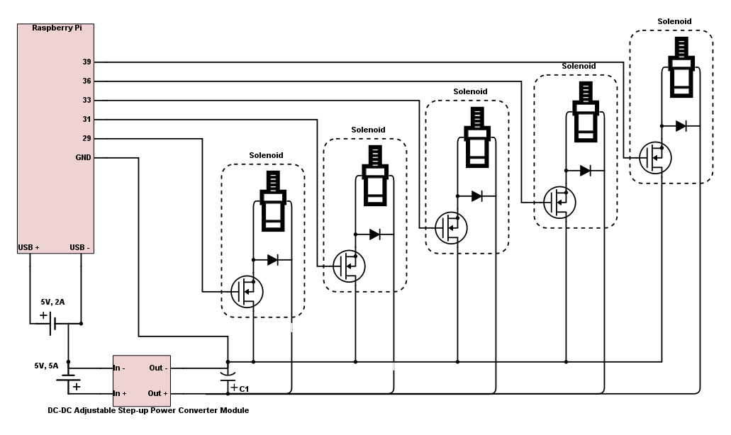
This is schematic of the current working circuit. There are important notes:
- I'm using power MOSFETs because the source-drain direction needs to handle up to 5A.
- Each solenoid has a bypass diode because otherwise the current can fall back when we switch off the solenoid.
- There is a capacitor in the circuit as well. The solenoids are switched on for a very short time, so that makes strong spikes in the consumption which can make the step-up power converter overwork.
- There are two independent power sources. The solenoids can consume up to 5A around 30V, even though it happens only for a half second. So the whole circuit needs 2A (RPi) + 5A (solenoids). This is not an ideal situation. I need your help to make it better.
- Be aware to connect all the grounds to the grounds.
This schematic is not perfect at all, but it works right now. I would really appreciate your help to make the circuit better.
Discussions
Become a Hackaday.io Member
Create an account to leave a comment. Already have an account? Log In.