Close
0%
0%

SCGA--> Self-Contained-Growing-Apparatus

Desktop greenhouse for cubicle growing.

Similar projects worth following
SCGA--> Self-Contained-Growing-Apparatus
Desktop greenhouse for cubicle growing.

I can't end global starvation by myself but maybe I can grow a salad for lunch while I am at work.
This is not a new concept, I have read about micro farms, nano farms and pico farms. This will be the femto farm.

But not the 3 square microns as seen here;

http://www.communitymicrofarming.com/wp-content/uploads/2014/03/Microfarming.pdf

Cost will most likely be ~$100 with a quantity of 1 with the PCB's and the micro (if the Teensy 3.2 is selected) being the most expensive components.

The self contained growing apparatus is an almost fully automated desktop greenhouse (the system will require a holding tank as there is no water hook-up at my desk). Fundamentally this is a bucket with dirt and seeds. The environment inside will be controlled to maximize the growing potential (attempt to maintain ideal growing conditions like moisture content of the soil, light requirements, etc. ) and over all efficiency of the resources consumed by the system.

Preliminary_Test_Code_05-24-2016.ino

Don't get too excited, I just grabbed some stuff from the examples and shoved it into a single UGLY sketch.

plain - 1.93 kB - 05/26/2016 at 00:28

Download

SCGA_1_Rev1-B3.fzz

Experimental PCB for developing project. Uses Teensy3.1 or Teensy3.2. DO NOT USE TeensyLC, the I/O are not 5 volt tolerant.

fzz - 95.54 kB - 05/24/2016 at 11:09

Download

SCGA_Rough_Sketch.pdf

Rough draft sketch of the self contained growing apparatus

Adobe Portable Document Format - 205.55 kB - 04/22/2016 at 15:36

Preview

  • 1 × Micro controller (maybe pro mini or Teensy3.2) One Controller to rule them all!
  • 1 × RTC (ds1307 or other) Real time clock for alarms, logging, etc (may or may not be necessary depending on the micro selected)
  • 3 × Drivers (like VND830) These wold be necessary to drive pump, fan and other loads
  • 1 × BME280 Temperature, humidity and ambient pressure sensor measure PV=nRT and adjust accordingly.
  • 1 × Water Pump small peristaltic pump

View all 15 components

  • 4x8 Led Array

    parkolay05/30/2016 at 01:23 0 comments

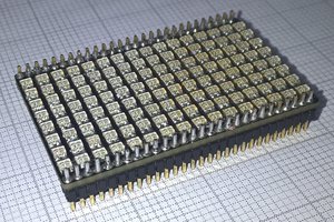
    This is a 4x8 LED array that should work for this project. The PCB is laid out so that I can choose to either go the traditional passive (simple) route or I can drop a couple of 16 bit LED controllers (TLC5940) that listen to the serial interface and have a 12-bit PWM output so I can control the level of light and depending on the LED selection I can also control the wavelength of that light through LED selection. What I have here is a preliminary PCB, there are some interesting drawbacks to using the the TLC5940. One I read about is if the LEDs have power but not your TLC5940, you run the risk of frying your TLC5940. I found this link (http://effluviaofascatteredmind.blogspot.com/2012/05/tlc5940-tlc5941-and-arduino.html) a wee bit late in my initial development of this PCB, but after I get my PCBs back from the PCB house I will do some testing slap some necessary blue wire down and then add some updates to the PCBs.

    I think I will modify the overall size as well to exploit the max size the PCB house is willing to fabricate.

  • Light supply

    parkolay05/29/2016 at 02:32 1 comment

    All plants need light, at least the ones that I will grow in the SCGA.

    I have some work completed on the LED board that will supply the light to my plants. I did some research and read that there are two specific bandwidths of light that are the most beneficial for plant growth. Quick Google brought me to this -->https://www.illumitex.com/impacts-colored-light-plants/

    Red light (640nm-680nm)Blue light (430nm-450nm)

    I will focus my efforts on these two spectrums and develop the necessary PCB to provide just these two for the added light for this project.

  • Don't forget your pull down resistors

    parkolay05/26/2016 at 00:20 0 comments

    Last night I sat down and wrote a bit of code to test the experiment PCBs. I have a servo, a DC motor, (ran by PWM from an analog input) to adjust the duty) and the LED connected to pin13 working. I did notice that I forgot my soft pull down resistor on the digital input switch that I added. OOps. Blue wire to the rescue, should be easy enough, there is a ground trace close to the switch that I can tie a 1k0 smd if I scratch the coating off the trace and drop some slobber.

    If anyone is following my other project, you will notice that these logs are very similar. If you don't like it, please feel free to add a comment and I will correct my way of working.

  • They have arrived!

    parkolay05/24/2016 at 01:01 0 comments

    The PCBs (to test the not yet written software using the Teensy3.2) have arrived and they test OK (except the one that I soldered the LM317 in backward!). I used an L293 Dual H-bridge driver for the fan and peltier device control. This way I can make the device shuttle electrons either way to warm or cool the heat-sink . The same goes for the fan, though I am not certain it will be necessary to drive the fan in both directions. The fan might end up being controlled by something else and I may use the second channel to drive a peristaltic pump, but again I don't know that I will need to drive that in different directions.

  • Overlord PCB

    parkolay04/28/2016 at 11:27 0 comments

    PCB was designed and sent to the board house. I will post files after I recieve the PCBs and test functionality.

View all 5 project logs

Enjoy this project?

Share

Discussions

Similar Projects

Does this project spark your interest?

Become a member to follow this project and never miss any updates