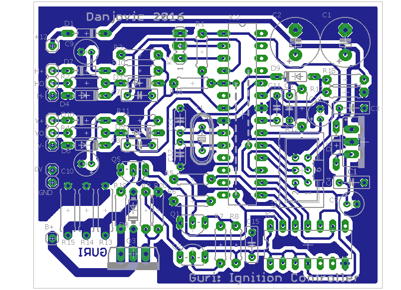
I've designed the printed circuit board for the prototype. It is a single faced design to make ease to build at home. It took me two jumpers to accomplish the task but they are hidden under the microcontroller.

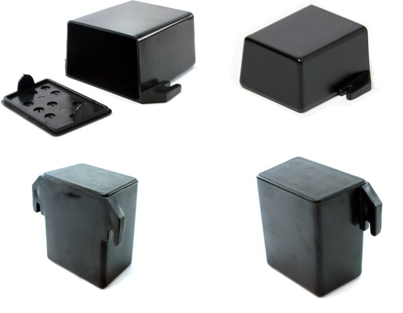
The board dimensions are 71 x 58.5 mm (2.8 by 2.3 inches) in order to fit into a CP-013 box manufactured by Patola.

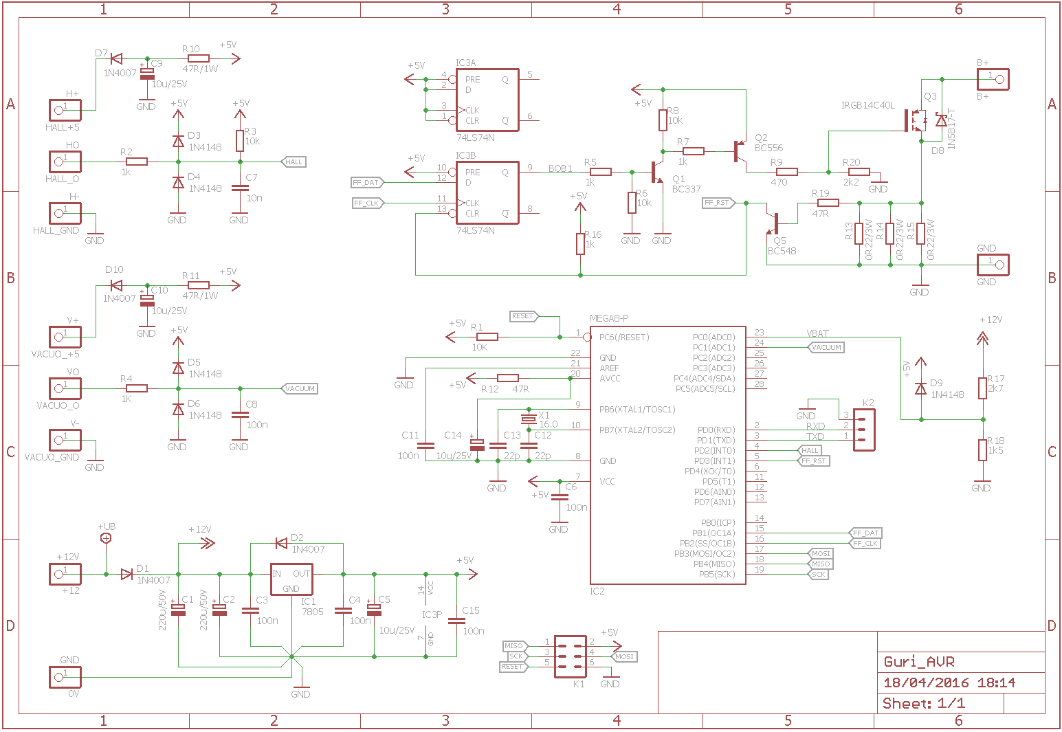
The circuit was some corrections proposed by @K.C. Lee (thanks). From the preliminary design I've added the series resistor in the base of the current sensing transistor (Q5) as well as the pulldown on the base of the IGBT (Q3). I've also picked standard value resistors of the voltage divider that will sense the battery voltage and added a clamp to Vcc to protect against voltage peaks above 19Volts on the high side of R17.

 danjovic
Discussions
Become a Hackaday.io Member
Create an account to leave a comment. Already have an account? Log In.