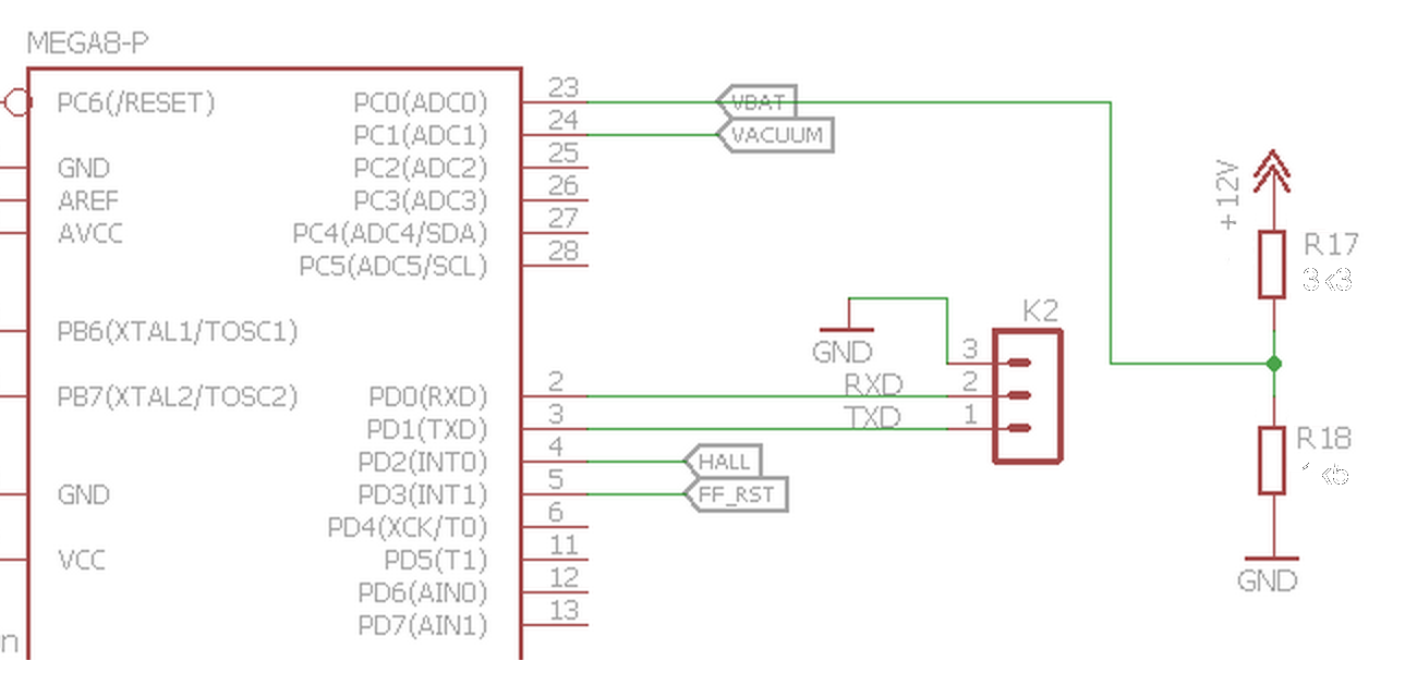
The expected operation range of the car battery is something from 8.0Volts during startup up to 14,2 Volts for the generator/alternator providing full charge at high engine speeds. Since the maximum voltage at ADC is +5V from the microcontroller Vcc the ratio between the resistors should be around the voltage ratio. Assuming a small margin on the upper voltage limit, lets say 15 Volts we expect a ratio of around 15:5 or 3:1. As for the voltage divider composed of two resistors, R17 on the upper side and R18 on the lower side the division ratio is (1+R17/R18). Playing with some E12 series values we pick the values 33 and 15 which gives a ratio of 3,2:1 which is close enough.

Knowing that the output impedance of the source for the AVR ADCs shall be less than 10KOhms we choose the resistors so the Thevenin equivalent resistance is about one degree of magnitude below or something around 1KOhm. Then by selection 3300 Ohms and 1500 Ohms for R17 and R18 we have an equivalent resistance of around 1031 Ohms which is again good enough.

With such values we have the following Counts on the ADC for the expected operation range.

 danjovic
Discussions
Become a Hackaday.io Member
Create an account to leave a comment. Already have an account? Log In.