 Vijay
Vijay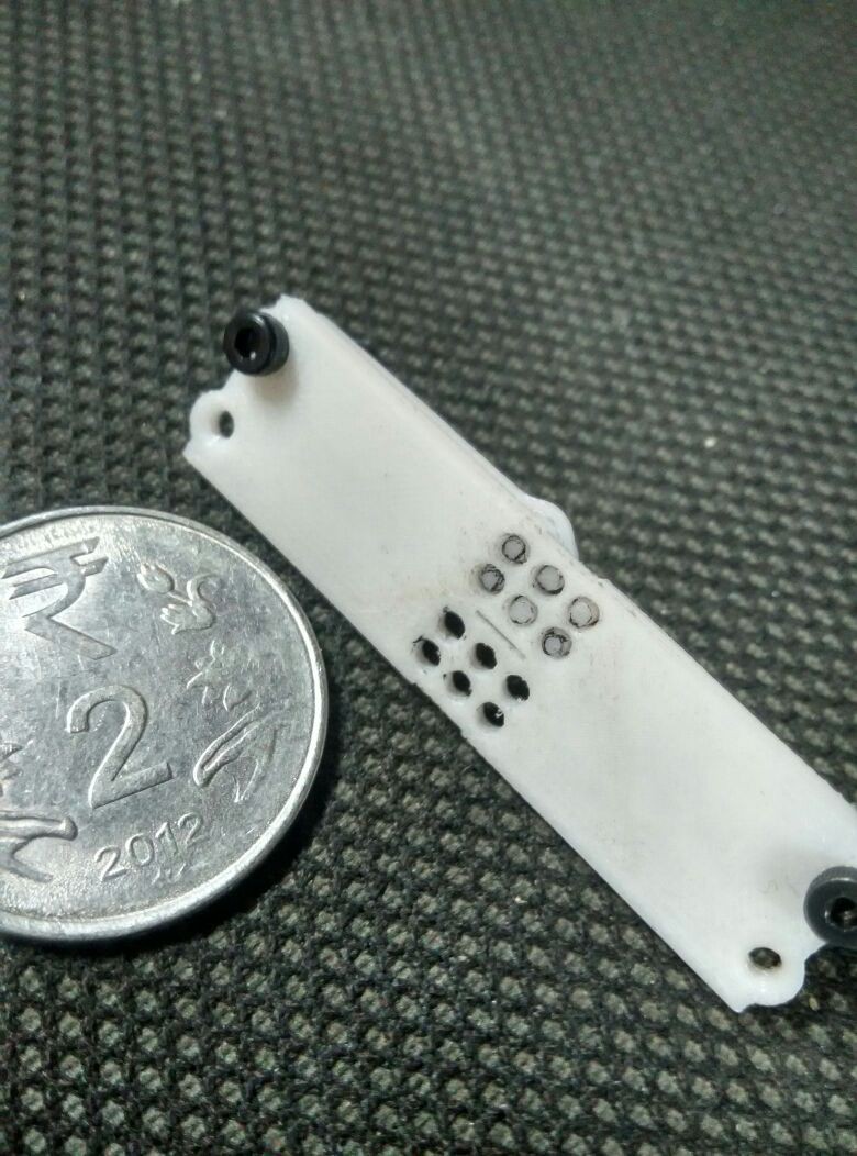
The above image shows the shaft-lever part into the braille cell plate. It took 4-5 iterations (available on the dropbox link) to get the tolerances just right, such that the pins don't get stuck in the shaft of the braille cell plate.
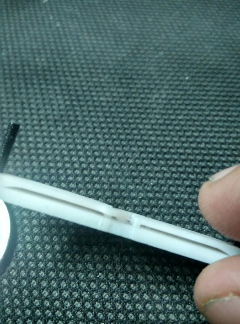
The above image shows the side view of the braille cell's, along with the pin-lever part assembled and held in place with an M2 screw. the pins are "below" the surface of the braille cell plate when not pressed, due to the spring action of the lever ( by the cam follower)
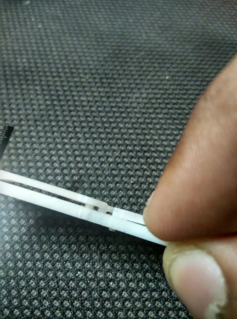
In the above image, I'm applying a slight force on one of the lever, that causes the pin to move up. Quite simple really.
Now its time to test with motors!
Discussions
Become a Hackaday.io Member
Create an account to leave a comment. Already have an account? Log In.