 Austin Marandos
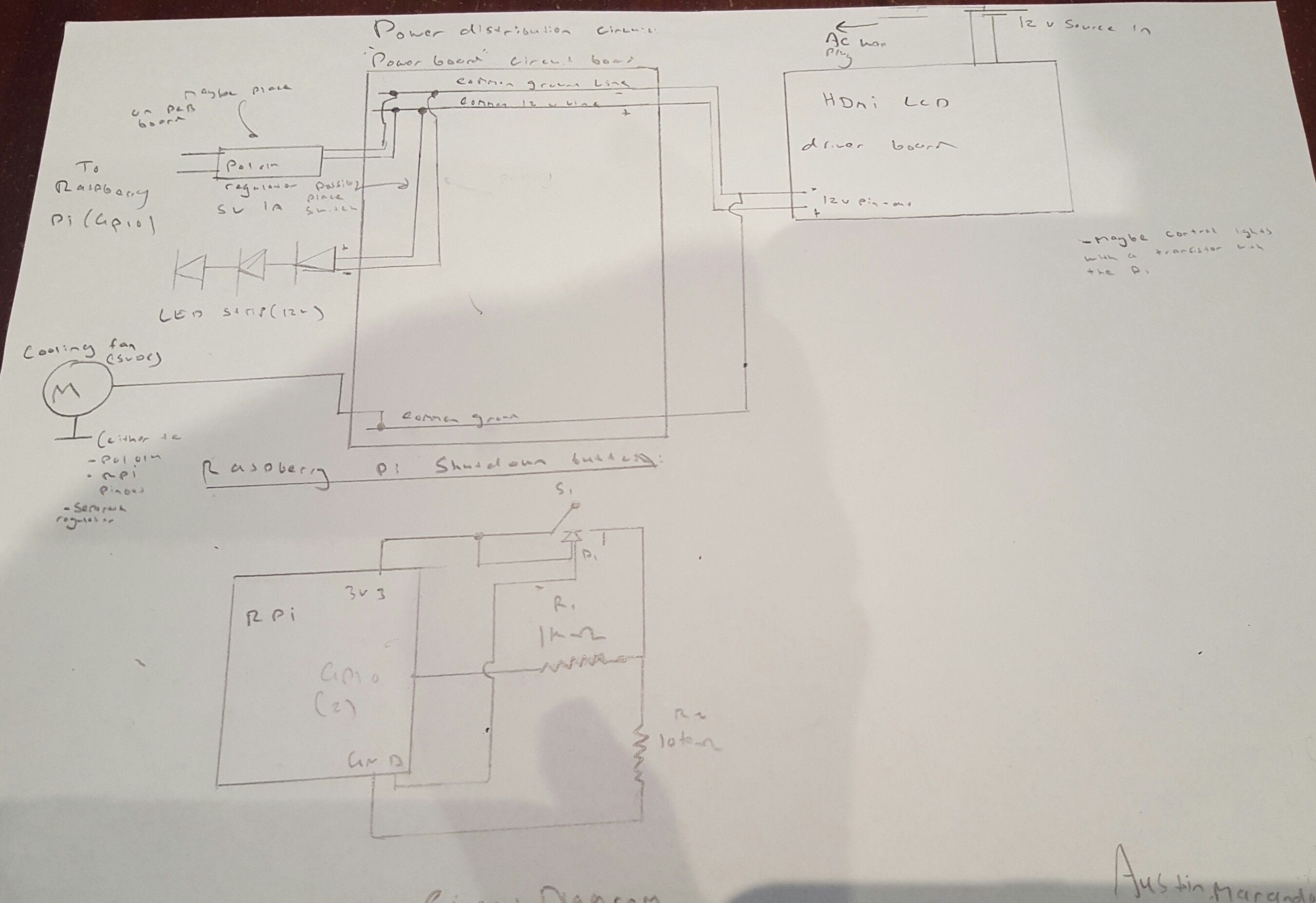
Once my design on Solidworks had been created it was time to construct the circuitry and program the Pi. The first step was to design and draw a circuit diagram,
Circuit schematic:
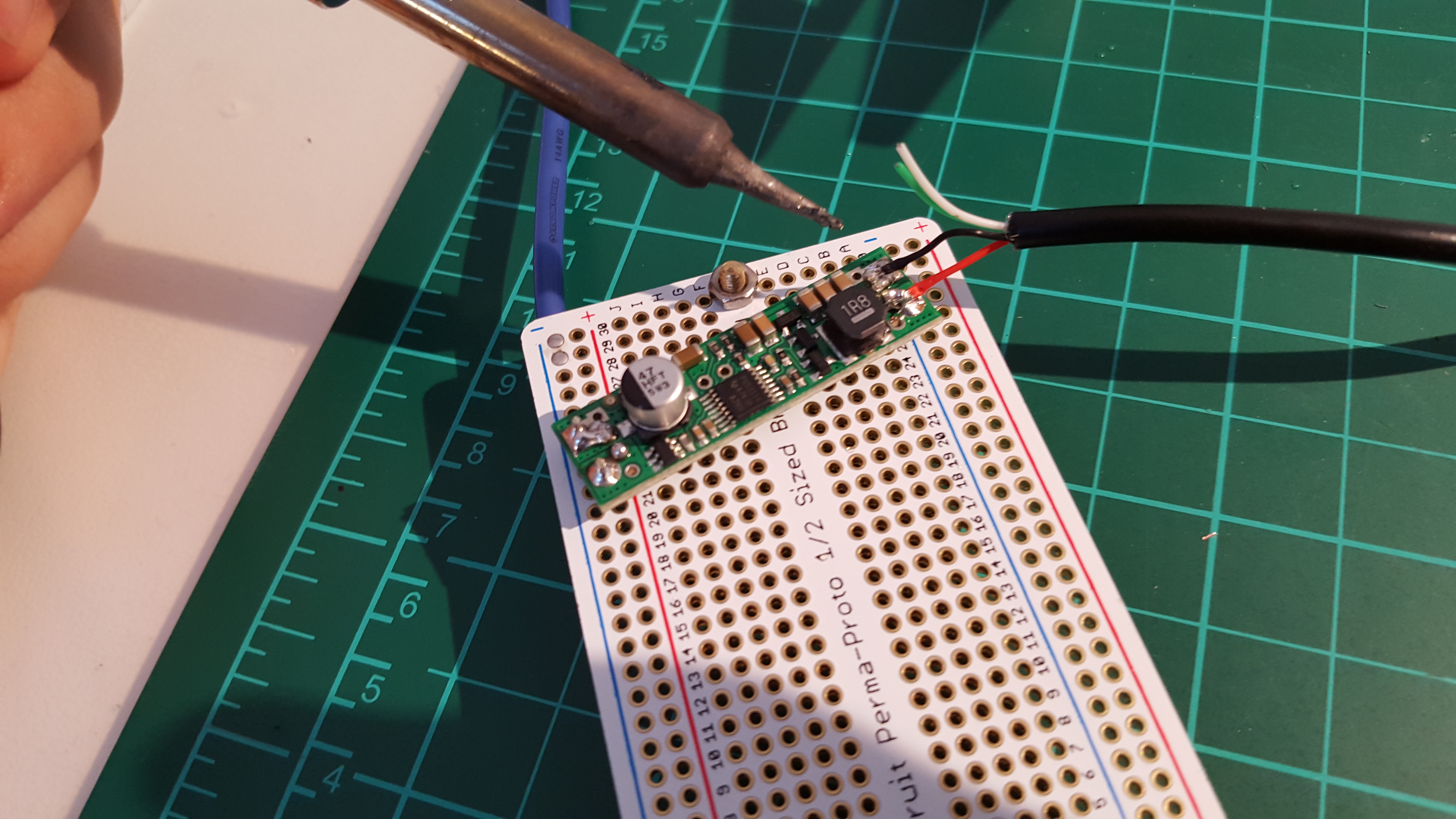
5V Regulator circuit. This is actually a motor regulator circuit but it worked fine on this project. Also it came with added heat monitoring circuitry
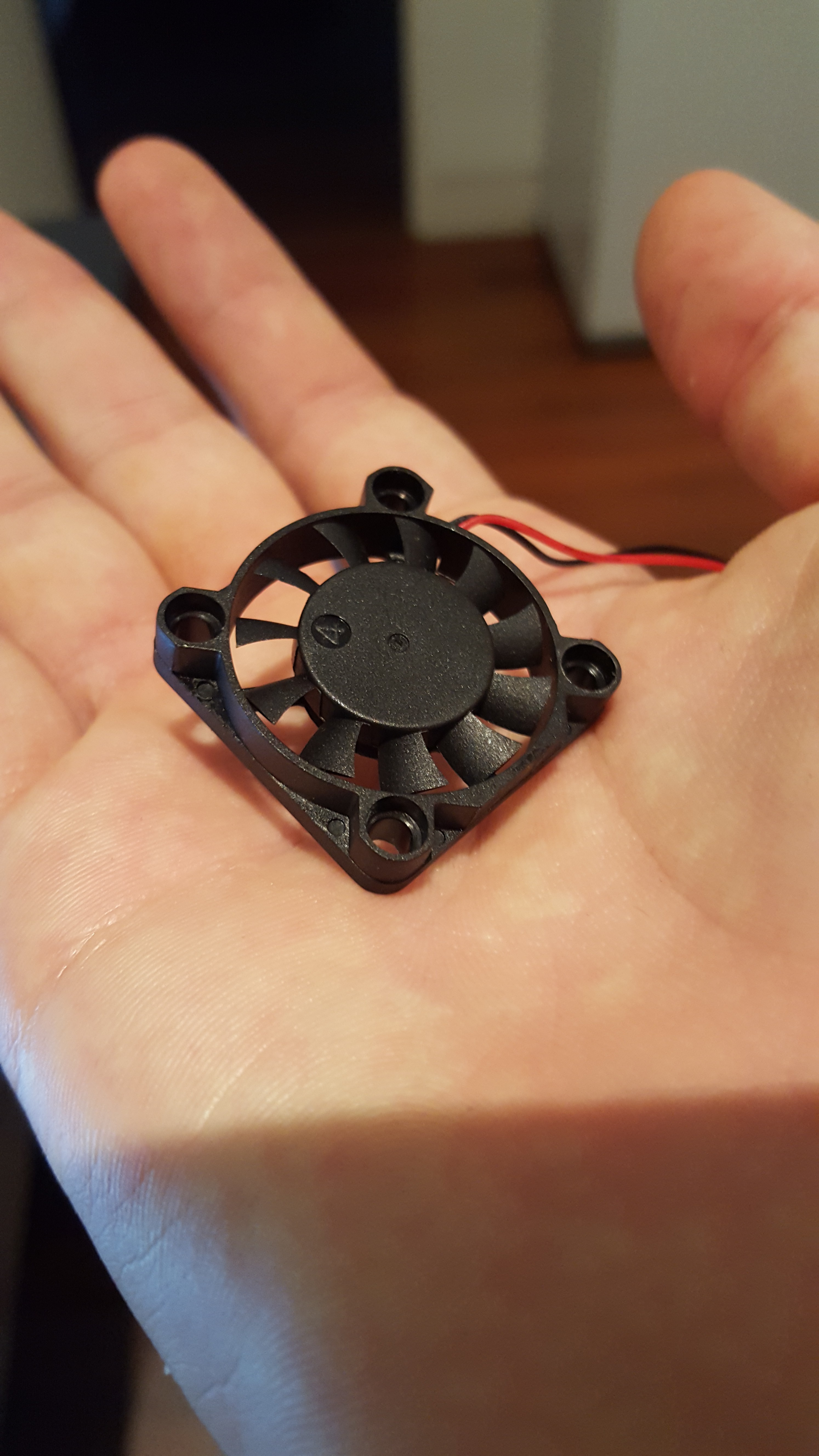
 An finally the 5V micro cooling fan. This thing actually worked wonders, it increased my Pi's performance drastically even though it was located at-least 5cm away from the Pi's CPU
Programming:
Most of the programming was completed following Gus' video from "Pi up my Life", his video which is linked in my sources section was extremely helpful and allowed me to begin the "Fe" image viewer upon boot up.
However due to the nature of my project I needed a USB to mount upon boot up and read all the images for the Feh image viewer from the USB. I also needed to create a python code that allowed a button to safely shutdown the unit.
The code and helpful contributers will be linked on the project page
Discussions
Become a Hackaday.io Member
Create an account to leave a comment. Already have an account? Log In.