 Tom Meehan
Overview of the some of the strip design details as well as the methods used in reading data from the strips and using it to determine blood glucose.
The Amperometric Method of determining blood glucose measures the electric current generated at a specific point in time by the glucose reaction (with either Glucose Oxidase or Glucose Dehydrogenase enzymes). This method, primarily uses either the:
Self Biased Configuration (2 electrode) Transimpedance Amplifier

or:
Counter Configuration (3 electrodes) Transimpedance Amplifier
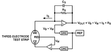
Illustration taken from:
Both of these methods amplify the current produced by the reaction of glucose on the test strip and convert it to a voltage. The voltage is then fed into an Analog to Digital Converter and the digital signal is interpreted by the microcontroller, using a regression equation, to output a blood glucose concentration.
Below are some of the different electrode configurations in the reaction area (at the tip of the strip) used by different manufacturers.
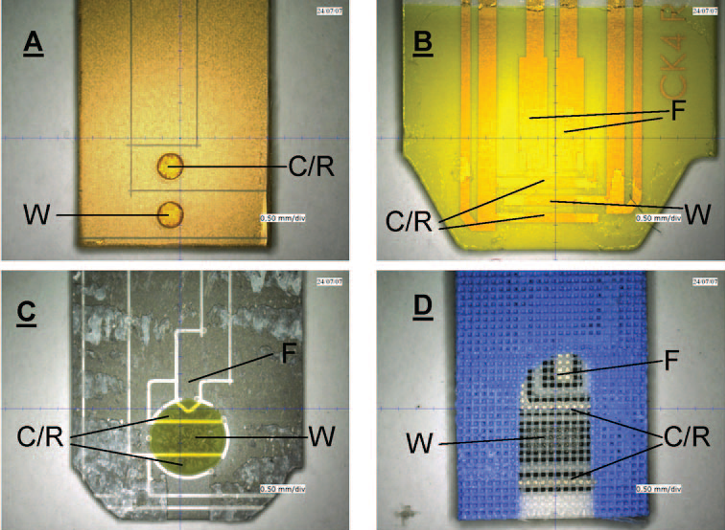
Figure 4. Small volume electrochemical blood glucose monitoring strips with their top cover layer removed.
- W: Working Electrode
- C/R: Counter/Reference Electrodes
- F: Fill Detrection Electrode
- (A) BD test strip, with electrodes in recessed wells in an insulating layer.
- (B) Accuchek Aviva, its fill electrodes doubling as hematocrit-compensation electrodes.
- (C) Ascensia Contour.
- (D) Precision Xtra with electrodes covered by a mesh.
Figure 4. taken from:
- Heller A., Feldman B. Electrochemical glucose sensors and their applications in diabetes management. Chem Rev, 2008, 108:2482-2505.
Discussions
Become a Hackaday.io Member
Create an account to leave a comment. Already have an account? Log In.