 Tom Meehan
My last post turned out to be premature - it did fix issues on the bread board version but the PCB continued to have issues (LCD back light would flicker but no text would show). It took a good deal of trouble shooting but I finally found that the Vcc pin for the LCD was, somehow, not connected to the +3.3v net on the Eagle schematic. It "looked" like it was but somehow they were 2 separate nets - meaning the LCD was not actually connected to power.
I was able to do a temporary fix to the PCB by soldering a jumper wire between the Vcc pin on the LCD connector to the Vdd pin on the PICkit3 programmer connector.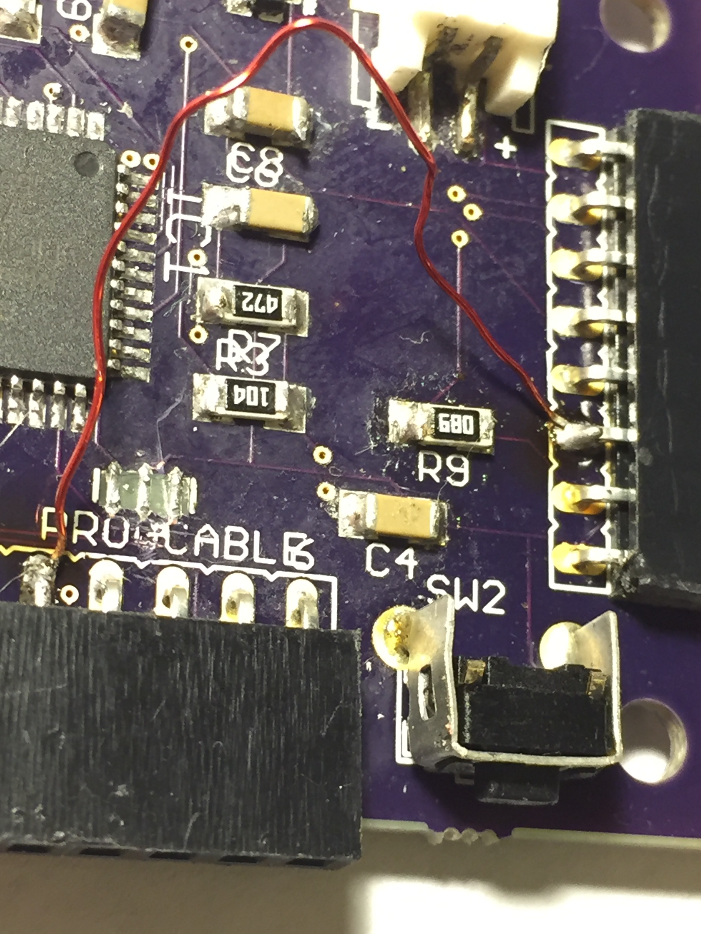
I'm rewriting the code from the ground up and simplifying the project (which should make it more flexible for others - easier to pull pieces from or add function to).
Busy trying to correctly set up an Eagle CAD "design file" repository on Github (really want it set up correctly so that I can update and "commit" changes and additions the right way).
Changing PCB design:
- 2 layer board (still) but all parts on one side. Previous board was my first effort at PCB design using SMD parts and 2 layer boards - in hindsight it seems much easier to place all parts on the front of the board. (Being a bit old school, 2 layers made me think "2 sided" - so I'm correcting that).
- Correcting the other errors I've mentioned (pin assignment for the resonator and Strip Sense pin).
- Method of sensing strip
- Adding 5th pin to strip connector (Strip fill sense detector)
Discussions
Become a Hackaday.io Member
Create an account to leave a comment. Already have an account? Log In.