 Yann Guidon / YGDES
Electromechanical relays use an electromagnet. An electromagnet is a high value inductor. And inductors generate high voltages (and worse) when their power is removed.
The traditional method is to use a diode acrosse the relay coil's pins. But I don't like this method, which amounts to heal instead of preventing. Well, in the case of relays, where the coils are driven by other relays, there's little to be done.
I favor dampening the pulse with a capacitor. But then it creates a new series of questions, such as
- polarity (electrolytic capacitors must not be powered in reverse)
- ESR (must be low, or it becomes useless)
- value/capacitance. Too high a capacitance and this keeps DFF from latching...
- actual voltage rating (the coils are driven by X volts but the pulse's voltage is much higher but this also depends on capacitance and ESR
I'll settle for 100nF/63V for now.: high voltage, medium value, low ESR.
For the rest of the dampening, I figured that diodes are necessary but the XOR configuration precludes the use of the traditional diode or electrolytic capacitor because the polarity of the current in the coil can change.
I'll clamp the coils to the power rails instead, using normal diodes (I got a reel of high-voltage ones, which should be enough) but when drawing the schematic, I realised something funny :-)
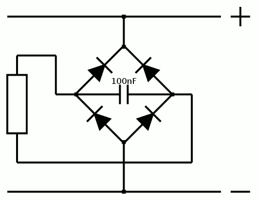
Yes, it's a full-bridge rectifier ! This means I have found a new use for the bridges I have in stock :-D
So even my XORs will not create arcs and jam the whole neighbourhood ;-)
Discussions
Become a Hackaday.io Member
Create an account to leave a comment. Already have an account? Log In.