 Yann Guidon / YGDES
Finally, a little overview of a "slice" of 4 bits.
This is convenient because 4 bits is the width of a TL311 input bus, it's the width of the hexadecimal rotary switch and ... a slice could be replicated "while supplies (of relays) last".
The overall system looks like this :
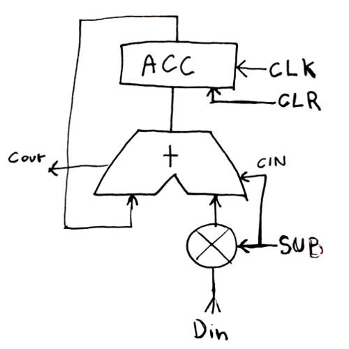
It performs add, subtract (thanks to the input inversion), stores a result in the accumulator, or clear it.
Not shown are the general control logic. TBDL (to be designed later, we can use buttons until it's properly figured out)
- The clock signal (CLK) comes from a button but later, from an oscillator.
- The CLR signal can actually be a relay that normally connects to +Vcc but switches it off when it receives a pulse. This will de-energize the relays and reset them.
- The SUB signal is GND when add (or "store") and +Vcc during subtraction.
- Din is the hexadecimal bus.
This will be changed a bit for multiplication and division but let's get +/- right first :-)
Translated into relays and a rough layout, we get something like this:
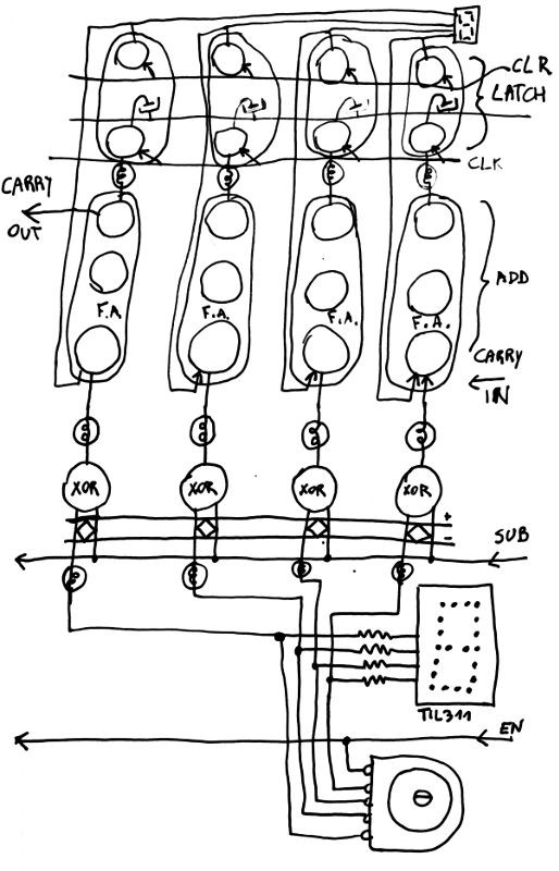
(I know, the drawing is a bit compressed at the top)
The lower part is the input with the hex switch and the TIL311 to display the number.
The 4 bits are lit and fed to a XOR (one relay, with a diode bridge at the input).
The nibble is fed to the adder, which is a chain of full adders (as covered in the rationale).
The other input comes from the DFF, (also covered in the rationale).
Load/spikes can be reduced if some relays are added to amplify the control signals
Things will get a bit more complex with the multiplies but no significant change is expected.
I should build an add/sub nibble (2 TIL311 and 24 relays) and then consider the multiplies, when all the easy details are polished... I'll also have a better estimate of the overall supply current.
Discussions
Become a Hackaday.io Member
Create an account to leave a comment. Already have an account? Log In.