 Yann Guidon / YGDES
The circuits that perform addition and subtraction can be reused in the circuits shown in this page : http://fourier.eng.hmc.edu/e85_old/lectures/arithmetic_html/node8.html
Multiplication and division require a shift register that is large enough to store the product or dividend. In the case of multiplication, I tried to redesign it in my head but I stumbled on the problem of the carry... The below drawing (taken from the link above) solves it finally :-)
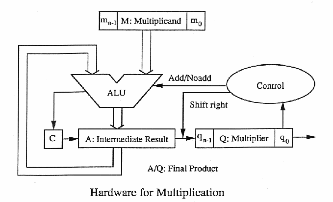
The multiplier should be loaded from the input so a row of relays is required to select the source of the input data. The accumulator (and carry) is cleared initially but another line of 16 relays must multiplex the accumulator's value to perform the shift, because in the add/sub mode, the accumulator is not shifted.
Division looks almost the same, but there's a catch.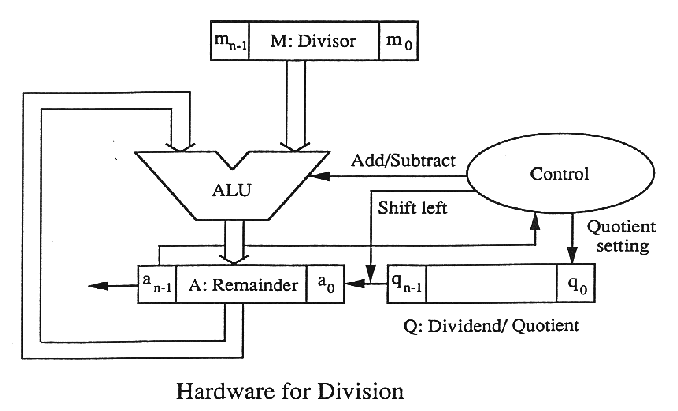
The shift direction is reversed ! So that's 32 more MUXing relays ! (and 2A of consumption)
I have not yet decided if I'll implement restoring or non-restoring division. Both are possible because I can either add 0 or add/subtract at will, it's just a different control signal to toggle.
Overall, that's 64 relays for MUXing and 64 relays for the 32-bits shift register. 128 relays are added to perform the 4 operations. The ALU is 4×16=64 relays already, 192 relays are needed and I don't even count the control logic or the amplifiers !
Discussions
Become a Hackaday.io Member
Create an account to leave a comment. Already have an account? Log In.