Yann Guidon / YGDES
-
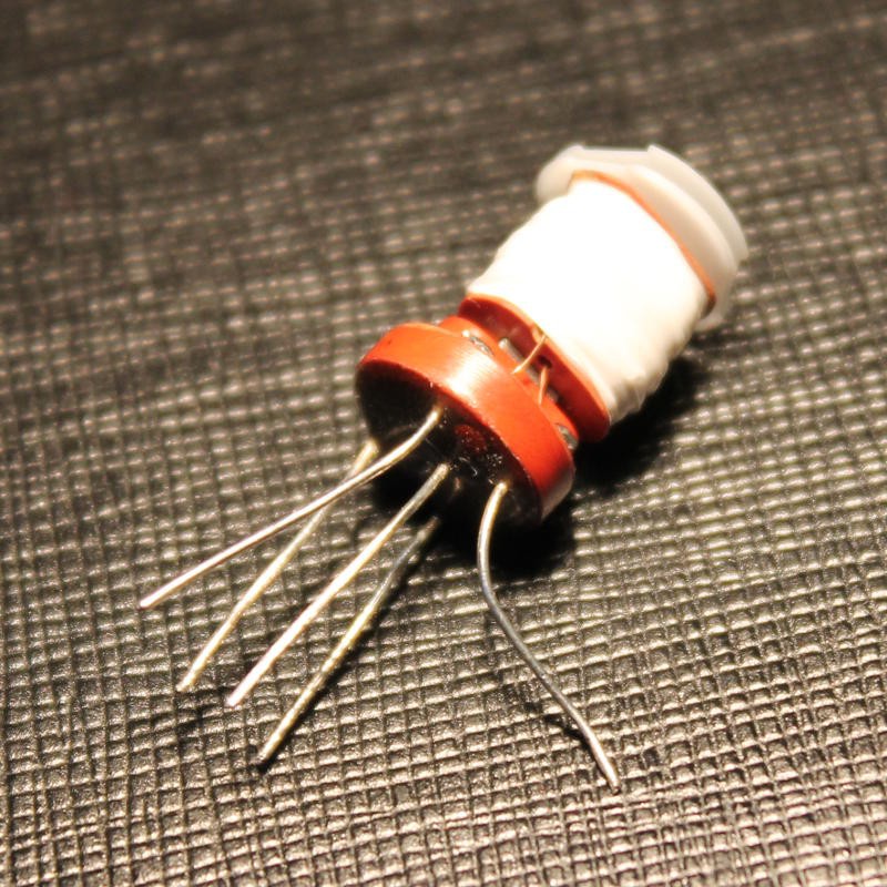
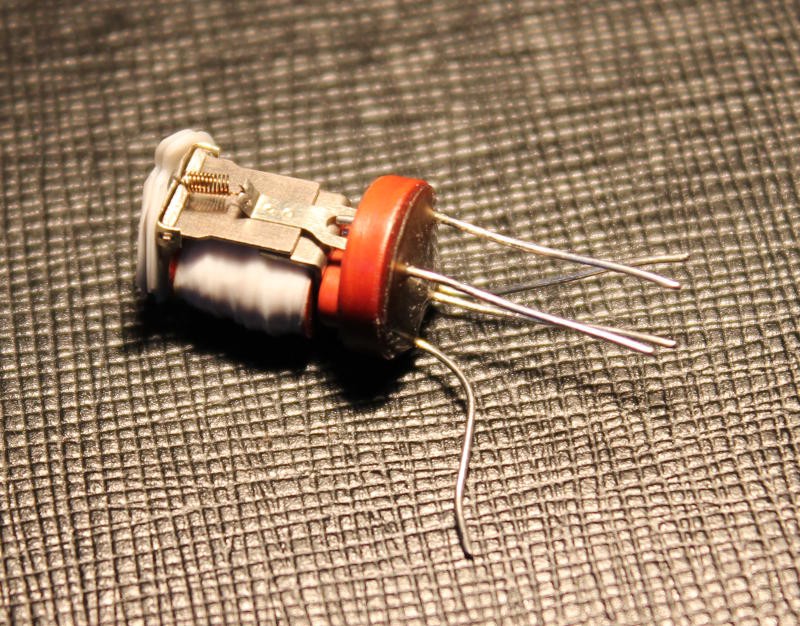
The relays are here too !
05/01/2016 at 08:59 • 6 commentsI now received some relays. It's time to characterize them !
Coil resistance : 35Ω
Coil inductance : 28000µH
Latching : 2V@0.06A (120mW ±20%?)
Release : 1.1V@0.04A (44mW ±20%?)
They are sold as 2.8V and I tested them with no load, I don't know how much current they can withstand. Anyway, switching 16 relays will draw 1A.
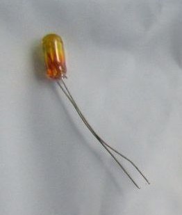
The coils look very compatible with the tiny incandescent lamps !
![]()
![]()
-
How can I make a low-frequency oscillator with a relay (or more ?)
05/01/2016 at 06:55 • 5 commentsThe multiply/divide mode of operation will require a multi-cycles sequence, hence some scheduling. I think I know how to make the logic part but... where does it get the synchronisation signals from ?
In the quare-root relay calculator, the sequences are generated with an electric motor and a cam. I don't want this. My best bet so far is a ring oscillator (3 relays?) with very large capacitors (I got that in stock, 15000µF is easy to find anyway).
Start/stop is as easy as inserting a SPDT in the ring to stick one coil to 0V for example. Once the start pulse is sent, this relay should be latched and the ring starts to oscillate. The "end condition" will release the control relay which will open the ring.
Easy.
In theory.
Yes I know, I should have googled that question before posting here. Shame on me.
Only one relay is necessary but a large capacitor is needed (2200µF?) and I'll need other relays (in series with the output ?) to drive the bunch of other coils to control.
I'm so lazy to make the diagrams though :-/
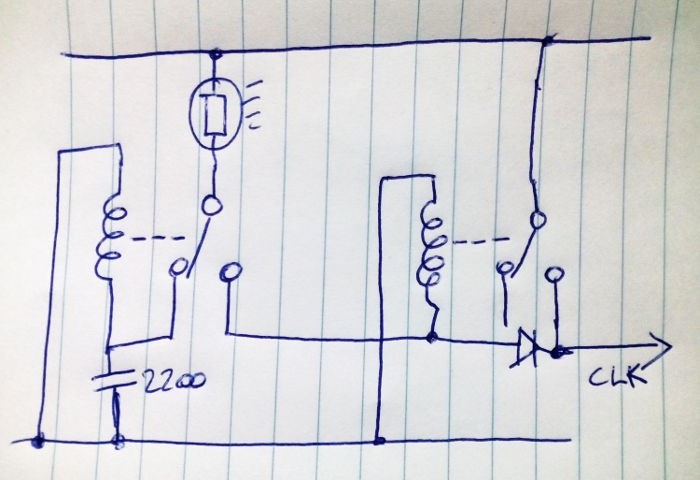
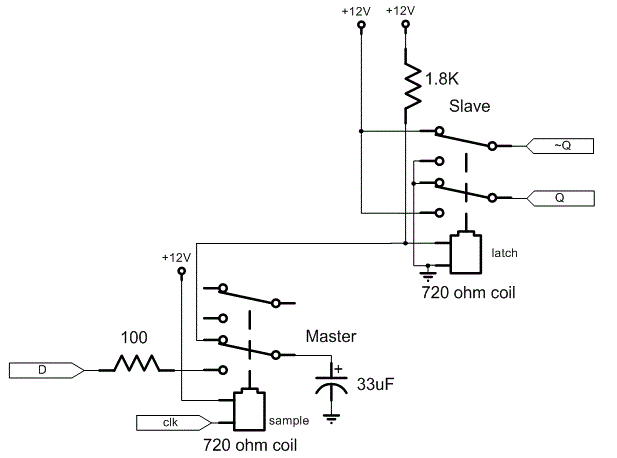
Now that's a good hint:
This "relaxation" version short-circuits its own coil, bad idea. But it gives me another idea ;-)
![]()
It could work...
- The lamp acts as a more or less permanent resistor to reduce inrush current (since it's mostly on)
- the capacitor acts as the reservoir, which makes a RC cell with the coil's resistance
- no need of a diode on the left relay because the large capacitor should handle the spike (if ESR is low)
- the right-hand relay acts as "buffer", its own coil's freewheel spike is reinjected in the slave coils (but who gets to dissipate the many slave coils' current ?)
Now, the trick of reinjecting spikes in other coils gets... interesting. Is it going to be a new sport/puzzle/game of this project ? :-)
Update : see Bad vibes
-
Die Glühbirnchen sind da !
04/29/2016 at 04:10 • 0 commentsI received the tiny incandescent lamps and they are cuuuute !
![]()
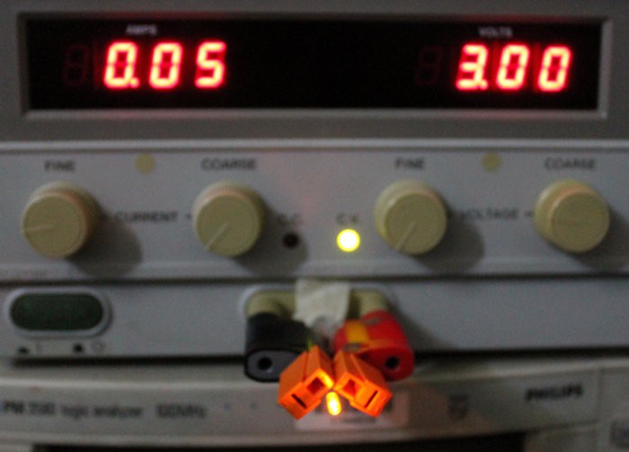
The initial electrical tests showed agreement with the advertised characteristics.
50mA@3V: check
![]()
In particular I'm interested by the potential interaction with the relay's coil during startup so I tried to evaluate the I/V curve with the crude reading of the power supply.
The following values are in "static" situation, with enough time for the filament to heat, at about 20°C ambiant temperature.
10mA@0,01V (it's mostly a short !)
20mA@0.14V
30mA@0.58V
40mA@1.27V (starts to glow)
50mA@2.17V
Should I put the lamp in series or parallel with the relay coil ? It might have have interesting advantages, such as proving the relay is energized but this can provide false negatives if the filament is broken, it forces an increase of current or voltage (more power) and the hysteresis (due to slower thermal characteristics) might interfere with relay operation.
- In series : the failure of the lamp will result in the failure of the relay operation. The interesting effect is during relay turn-on : the lamp is initially cold and will let all the current pass. The heating time might be in the same order of magnitude as the relay actuation so by the time the lamp is hot and reduces the current (becomes resistive) the relay should be working. This should result in a reduction of coil current with a moderate increase of operating voltage (4V at the supply ?). The lamp will glow lightly, depending on power voltage and relay characteristics (TBD) but I don't need the thing to blind the viewer :-)
For release, I don't know if the clamp diode must be before or after the lamp. Keeping the lamp in the loop will help dissipate the energy faster and let the coil release easily. Otherwise, clamping to the power rails will work too... - In parallel : This is interesting for the release, helping keeping the current flowing through the coil (maybe replacing a clamping diode).
However turn-on will almost make a short-circuit (the lamp will dominate the inrush current), thus increasing noise in the power supply rails.
So it's mostly a question of "do I make noise when the coil is switched on or off ?"
This will also depend on the coil's characteristics so I'll have to test both circuits. The decision might depend on the power : parallel increases the current, series increases the voltage. I suppose series might win but measurements should decide.
Oh and 4V would make it compatible with the TIL311 power requirements...
- In series : the failure of the lamp will result in the failure of the relay operation. The interesting effect is during relay turn-on : the lamp is initially cold and will let all the current pass. The heating time might be in the same order of magnitude as the relay actuation so by the time the lamp is hot and reduces the current (becomes resistive) the relay should be working. This should result in a reduction of coil current with a moderate increase of operating voltage (4V at the supply ?). The lamp will glow lightly, depending on power voltage and relay characteristics (TBD) but I don't need the thing to blind the viewer :-)
-
Power supplies (2)
04/18/2016 at 02:27 • 2 commentsSince the voltage is settled to 3V, the next step is to provide it with a suitable current. I expect the consumption to be significant: if one relay coild draws 1/2W, a whole system with 200 relays will draw 100W !
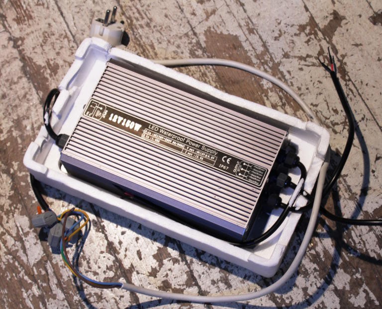
So let's start with finding a beefy power supply in this range. I have this one:
![]()
Is 150W enough ? If not, I can find another.
(Edit: yup, while looking at another old project, I found a brand new 12V 30A "brick". With a fan. Now I hope it's sufficient.)
Now this outputs 12V but SPDT16 needs "around 3V". I must use "point of load" DC/DC step-downs. The advantage is that the current out of the main PSU is lower and the power rails are split, which increases reliability a bit and reduces the propagation of power spikes.
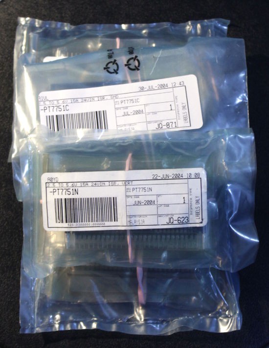
I have a few 14A regulator modules from PT/TI (the old "Big Hammer") with adjustable voltage output but these accept 24V and not 12V. Too bad, they look rad. Next time, maybe...
![]()
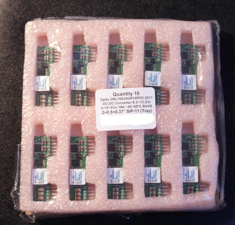
But then I remember I bought some incredible and cheap DC/DC modules on eBay (look them up, they're amazing).
![]()
Now we're speaking:
- 12Vin : check
- 16A out : check
- 3Vout (adjustable): check
and smaller as well !
So I can plop one of these to power a section of the circuit, which will be somewhat isolated from the rest, while slurping amperes from the main PSU. I can locally adjust the working point to draw less power.
I knew it was a good idea to buy them !
(I added the datasheet to the files section)
Now I have to find/add "suitable" capacitors...
(update 20160401)
OK, I may have overestimated the power consumption.
At 150mW (max?) per relay, 200 relays will draw 30W.
At .08A (max?) per relay, 200 relays will draw 16A.
So one SIP module will be enough :-)
Another module might be necessary though for the TIL311...
-
Rationale and general idea
04/17/2016 at 23:25 • 0 commentsThis is the contents of the Project Details page but it was getting too long so I moved it here ;-)
External references
I wouldn't jump head-first like that without some good resources that encourage and feed my curiosity ;-)
Of course I heard about Zuse's computer but my first exposure was when I was part of the Homebuild CPUs webring and I encountered projects such as Harry Porter's or TIM-8.
Some naughty dutch guy woke the devil with his #Relay Logic Clock and I should give it even more attention...
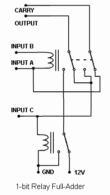
But the last trigger was Basic Relay Computer where you can find such enlightening drawins as the following:
![]()
This means: one SPDT and one DPDT, or three SPDT. My idea becomes possible.
Then the last straw is the storage, explained at http://relaysbc.sourceforge.net/circuits.html
![]()
It becomes possible to design a circuit with a low relay count. However a mix of SPDT and DPDT seems desirable, less coils,less noise, less power consumption !
Here is a rough analysis of the parts cost of a 16-bits computation unit:
Addition
This is pretty easy and uses about 3 SPDT.
Multiplied by 16 bits: 48×SPDT.
Subtraction
Again, easy : XOR the subtractand and set the carry input.
XOR is one SPDT, plus a big switch to select the function, so that's 16 SPDT.
Multiply
The above was pretty easy but there are some relays left in my virtual budget. Multi-cycle multiplication is possible by reusing the adder, and with the help of a rotating register.
Division
If you figured out the multiplication, the division is almost as easy, but by iterating subtractions and rotations, instead of additions.
Registers
Using the capacitor trick, it's possible to implement a DFF with 2 SPDT and a capacitor. However the source data must be chosen (input dials or adder's result) so that's 3 SPDT. Division requires an additional mux to select the shifted register or the Adder's output, in case the carry/borrow is set... 4 SPDT, 128 relays. I should refresh my memories about restoring and non-restoring division, I think...
Update (20160501): No MUX2 ! see A sick trick for the multiplies. This saves at least 16 relays (I might extend the ALU to 20 digits then) and the accumulator would be loaded through the adder (by clearing the mulpliplicand before addition).
I should also check HOW it is possible to compute a 32-bits number with only a 16-bits adder. The 8086 did it this way, 35 years after Von Neuman described how to do it, but I forgot the details...
-
Glühbirnchen
04/17/2016 at 22:03 • 7 commentsSo in the spirit of the precedent log, I found tiny incandescent lamps that just fit the bill. Rated at 3V/50mA, I have a set of 50×red, 50×blue and 50×orange and I think they fit nicely with the theme of the project (power hungry). Imagine 16 or 32 of these, blinking as computations progress:
![]()
Of course I've thought about using LEDs. But these are fragile semiconductors that won't like the repeated spikes on the power supplies, even though I can add a resistor in series and a capacitor in parallel. That's quite a lot of parts. However a 60 Ohms load across the coil will help absorb the spikes.
Now I have one color for the 32 (48?) input bits, another for the (intermediary) results and another for the control signals.
To hell with saving power. I'm not building a Bomb/Colossus...
PS: Glühbirnchen is the german word for "tiny glowing bulbs". I hope you learned something today :-D
-
SPDT×72
04/16/2016 at 18:41 • 0 commentsSorry, dear bank account. I had to try those russian SPDT mini relays. 72 should be enough to make a nibble/prototype, hopefully. They are not the cheapest and they are not DPDT but they look really cool on eBay.
Now I will have to find a POWERFUL power supply and suitable "Point of Load" DC/DC modules to supply 3V. There must be something like that in my archives...
-
Freewheel diodes
04/12/2016 at 15:21 • 0 commentsElectromechanical relays use an electromagnet. An electromagnet is a high value inductor. And inductors generate high voltages (and worse) when their power is removed.
The traditional method is to use a diode acrosse the relay coil's pins. But I don't like this method, which amounts to heal instead of preventing. Well, in the case of relays, where the coils are driven by other relays, there's little to be done.
I favor dampening the pulse with a capacitor. But then it creates a new series of questions, such as
- polarity (electrolytic capacitors must not be powered in reverse)
- ESR (must be low, or it becomes useless)
- value/capacitance. Too high a capacitance and this keeps DFF from latching...
- actual voltage rating (the coils are driven by X volts but the pulse's voltage is much higher but this also depends on capacitance and ESR
I'll settle for 100nF/63V for now.: high voltage, medium value, low ESR.
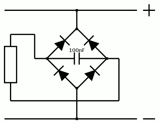
For the rest of the dampening, I figured that diodes are necessary but the XOR configuration precludes the use of the traditional diode or electrolytic capacitor because the polarity of the current in the coil can change.
I'll clamp the coils to the power rails instead, using normal diodes (I got a reel of high-voltage ones, which should be enough) but when drawing the schematic, I realised something funny :-)
![]()
Yes, it's a full-bridge rectifier ! This means I have found a new use for the bridges I have in stock :-D
So even my XORs will not create arcs and jam the whole neighbourhood ;-)
-
Power supply
04/12/2016 at 02:24 • 0 commentsThe first question, before I start, is the choice of coil voltage.
I have set the bar at 200 relays so I must estimage the required energy when all the coils are activated.
The lower the voltage, the lower the resistance, the higher the current...
I could undervolt the system a bit using 3V or 5V relays will require large busbars.
The question of fanout is important as well, because some things will switch 16, 32 or maybe 64 coils at once. That's a lot of current ! So I don't look at 2A relays like before ("why do I need so much ?")
SPDT16: 16-bits arithmetic unit with relays
Let's imagine I could get about 200 SPDT relays. Of course I would know what to do with them :-D But will 200 be enough ?