KingOfKYA(Travis K. )
-
Quick Explanation of raptor12
08/16/2014 at 23:10 • 0 commentsAKA the 2min video for hackaday prize entry.
![]()
-
Small update code on github
07/26/2014 at 19:39 • 0 commentshttps://github.com/komby/RFShowControl/blob/master/examples/RF_In_SoftPWM_Out/RF_In_SoftPWM_Out.ino
Just cleaned up code I also made the leds function led on the right turns on if the nrf radio is detected and working.
The second to the right blinks when data is being sent.
Also Component list is now up to date on hackaday.io here is the list i update more often
https://docs.google.com/spreadsheets/d/1uF-vKyBJ3zwXyiN5ztA2IU1x8GdDw2qsmtBHZrETNNE/edit#gid=0
-
Firmware ready to go.
07/22/2014 at 15:44 • 0 commentsFor about a week I haven't been able to get the code working 100%, occasionally i am getting to where the code appears to get stuck.( during radio.Listen() ) Or for about 3 cycels of the ac wave. It seams to be disabling interrupts or something.
However on the test and DMX transmitter if i hold reset and stop the data the code is stable and never misses the correct dim point. Its only when there is data in the nrf buffer I think.Thanks to sporadic at the diychristmass.org forum mentioned.
"The radio is only being queried for packets every 7.7ms or so. Dunno if its related to your issue, but you may be overflowing the nRF RX pipes as well."
I fixed that it started working almost perfectly, I was still getting a slight error but every 5min or so. After reading up on the avr interrupt stuff and figured out i was likely getting an error because of the non even way 16mhz divides into the AC dimming timeing. Any way my quick way to fix it is just reset the timer to 0 when zero cross happens. Haven't seen any glitches yet:)
![]()
![]()
Here is what I ended up with (needs to be cleaned up).
http://kneale.us/raptor12/ver7/RF_In_SoftPWM_Out_Night72114.zip
-
Problems with 1.0 board
07/19/2014 at 20:26 • 0 commentsFirst thing clearance The top of the fuses of the ac/logic board and the rectified positive voltage can easely be shorted together if the top board is flexed do to the use of a flooded copper region on my top fet driver board. Easy fix for this prototype i just found some scrap pcb and superglued it to the bottom of the fet board.
![]()
On this revision i also removed the lower screw holes as there really not needed. Then when adding the second offset nrf footprint i managed to move the 3v regulator to where the original screw hole was. So there was a plastic stud that is now in the way of the voltage regulator. So i had to put the components on the revers side of the board.
![]()
I added this jumper to allow for testing of the power supply before it is connected to the micro and the rest of the board. But on the silkscreen i put it on the wrong side. Oh well another easy fix.
![]()
The tiny to-92 transistor that i original specked didn't cut it with the micro running at full speed it was overheating and failing. So now I have a to-220 transistor in there a tip120. I also had to adjust 2 resistor to setup the biasing correctly for the new transistor that has a higher gain the 2 blue resistors in the pic below. Ignore the flux mess i ran out of the no clean stuff, this stuff is harder to get off.
![]()
SO getting there hopefully one more board spin:)
![]()
-
Second test of v1.0 board
07/13/2014 at 04:10 • 0 comments -
First live test of v1.0 board
07/12/2014 at 02:51 • 0 comments -
PCBs
07/05/2014 at 20:42 • 0 commentsThat mailman finaly showed up, Its Christmas morning:)
![]()
![]()
![]()
Also here is the aftermath i just cleaned it...
![]()
-
Final PCBS:)
06/19/2014 at 06:51 • 0 commentsI am reasonably sure everything will work:) Boards are off to the Fab then some performance testing:)
Now to wait for the mailman, because i was too cheap for dhl.
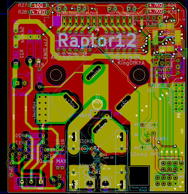
Bottom Board logic/AC
![]()
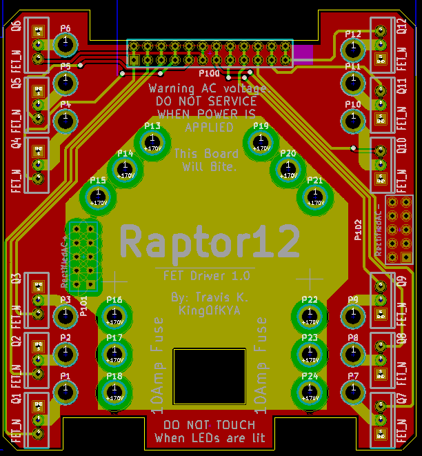
TopBoard FET Driver
![]()
Optional board extra Indicator LEDs
![]()
-
Time to give the code away:)
06/15/2014 at 05:53 • 0 commentsGot the code for my controller done and code submitted to master branch.
-
Found my noise / pay attention to data sheets.
05/21/2014 at 03:29 • 0 commentsUpdate:6-18-2014 This was not the real issue, the real issue was overheating the transistor, i added a second zener to the circuit to add some feed back so it is not blindly dumping power.
I specked in the MPSA42 npn transistor so if i need to to later it would also work as a high voltage transistor in case i need more power for driving SCRs/Triacs anyways i need to read data sheets better because its not a very good chose for the power supply circuit. It responsible for driving the fet low however in practice it create an oscillating gate pin that is just amplified by the fet. SO now i need a transistor that can drive the fet low faster without oscillating.
http://www.fairchildsemi.com/ds/MP/MPSA42.pdf
The big issue is the DC current gain aka: how well the transistor amplifies signals in this case its 25-40 so i happen to have a few other tranisters unfortunately in other pin orders and foot prints, anyways so i had a pack of tip120 transistors sitting around. TO220 package i think they fit just fine:)
![]()
http://www.onsemi.com/pub_link/Collateral/TIP120-D.PDF
Anyways on the TIP120 it has a gain of 1000 much better at driving the signal to the fet low.
Here is what the corrections look like:)
![]()
Raptor12 Wireless AC Dimmer
Christmas, Halloween light string controller that is wireless, 12channel dimmable AC controller, with an AVR for $30