KingOfKYA(Travis K. )
-
Ring Ring its IRF730
05/16/2014 at 05:46 • 0 commentsOpen question does anyone know how i would go about removing the noise the main switching fet is making.
I have been reading this:
http://www.ti.com/lit/an/slpa010/slpa010.pdf
Page2 is basically what I am seeing.
Also get the same ringing when the with the micro and radio power disabled. So i am pretty sure its the fet. That i confirmed when i ground its gate and the noise went away but so does my power supply so that is not a solution:)
Also if i am being stupid with the component choice let me know:) i don't mind being wrong.
Schamtic/Simulation:
-
Version 5 Final Version?
05/14/2014 at 04:17 • 0 commentsThere seams to be some variation in the nrf modules The cheap $1-2 ones are off set to one side of the pin header. While the PA($10-30) aka: amplified version has the same width but it is centered rather than offset. So now my layout has 2 sockets that do the same thing.
I have ditched my conventional 3.3v regulator and instead I have built a very simple negative 3.3v regulator, that gives me a little bit more protection from burning up the nrf chip, that can happen if the 5v data lines come up before the 3.3v lines. Now the nrf module VCC is at 5v and GND is at 1.7v. So as far as the NRF can see it is being powered by 3.3v and data is at that level as well.
You can see in the pcb layout I am using 3 10ohm resistor, the reason is very simple:) Less parts on the bom.
Also I removed the lower screw holes there really not needed the top too provide plenty of suport.
![]()
The other change i did is Expand the board up by 6mm, now it should be aligned with the top pf the box. Also some status leds you can never have too many especially if you play to sell something as a kit. Also i got relly lucky here to match my other leds I need a 4.7k resistor @ 5v and i already have 4.7k in the bom another great coincidence.
![]()
-
It works:)
05/09/2014 at 05:45 • 0 commentsI still want to clean up the code a bit before releases but anyways here proof that its working:)
-
Ardueno land... sometime you need to walk away.
05/09/2014 at 05:33 • 0 commentsSo if anyone else ever attempts this don't use the arduneo digital write its far too slow but easier to understand that was another sub goal of this project to make it easy for someone to adapt what i did perhaps even in a more conventional diy controller.
Anyway its a bit hard to read but this what i came up with. Komby you made this too easy i just droped you code in and it worked. I will upload to git hub after a bit more testing. https://github.com/komby/RFPixelControl
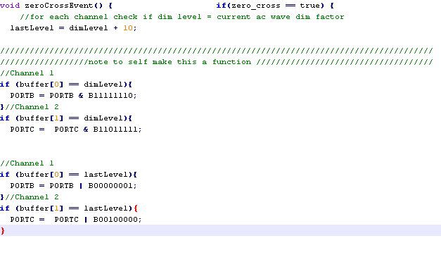
So here is the ardueno code i started with:
![]()
Pretty simple and very easy to under stand it basically take an array of data that contains the names for all the pins the loops though them turning them on or off as need. This works but its a bit too slow just this code with a static dim level hard coded i was only able to get about 127 levels of dim, that might sound ok but that also leaves me no time to do anything else like talk to the NRF radio. Also with my input being a dmx like stream from the NRF radio. aka:256 dim level i need to at least get to 256 dim levels. Or i have no reason to finish this project, have to be better than what out there or whats the point:)
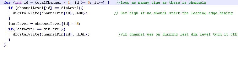
So some less readable code.
![]()
So I am basically doing the same thing as before but i am avoiding the overhead of digital write. I am talking directly to the pins of the atmega328. That leads to another complication because to write to the pins you need to update all pins attached to that port in the case of the atmeag 328 that portB portC portD. If you google for "port manipulation arduneo" you can fine lots of help on what Ardueno pins translate to Ports, alternatively you can also just pull up the data sheets for the micro your using.
-
Prototype Time again
05/08/2014 at 01:22 • 0 commentsIt fits perfectly, Test video below:)
![]()
![]()
04-16-2014, 07:37 PM
-
Bringing it all together
05/08/2014 at 01:19 • 0 commentsSo now i got the PSU, case and now i just added my new psu to the circuit.
![]()
This board gets stacked on top and has all the scr on it.
![]()
-
Simple Cheap 5v PSU
05/08/2014 at 01:15 • 0 commentsBefore i get too far into this this is a NON ISOLATED 5v supply really only for driving a small micro . What this means is you can not connect PC, scopes or any other ground test gear without understanding where and how your earth ground interacts with the circuit. Also it should NEVER be used when there is a chance a user can come into contact with the curcuit.
My equipment:
1:1 isolation transformer this alowes my to safely probe with the scope because it removed the ground from the AC mains.
usb isolator: so i can plug my pc in for debugging with out any real risk.(note to self add pics)
Ok after about 4 revisions of my psu, and a lot of reading. I came up with this circuit.![]()
Yeah that is right who needs bread board just do it in free air:) Here is the total bom for the psu for $1.16 Yeah, you read the right $1.16 no way you can find a transformer in hobby qty for that price. Also i know i should not solder a fuse but I could not find a holder around.
http://kneale.us/raptor12/ver4/PSU%20BOM.pdf
This curcit is a bit more complex than the cap dropper psu but its still pretty easy to follow.
The first npn tranistor on the left, is responsible for turning the Mosfet off when the power on the ac gits too high. If you look at an ac sign wave you can see the voltage varies. so when the voltage is below say 0-20v we use that because it is far more manageable heat wise. So use some simple transistor logic: I attach a two 120kohm resistor to the base of the transistor so as the voltage rises it will eventually trigger and force collector low. Now on the mosfet you will see a single 120kohm resistor attached effectively pulling it high all the time. That allows me to chop the low voltage out of the 120v+ Ac signal.So now we have what should be crude low voltage but but we have the potential for a large spike or other ac glitch to get into our low voltage supply, That is where the next NPN resistor comes into play. It acts as a current limiting circuit that slowly ramps up the voltage in respect to its gate pin that is slowly charges up via the resistor.
Then a filter cap .22uf in this case, connected to a 10ohm resistor (just to stop some of the noise) and a zener diode that is being used as a shunt regulator.
Java simulation
-
Failed PSU Designs
05/08/2014 at 00:44 • 0 comments(just a placeholder i need to go take soem pics)
-
Circuit simulators
05/08/2014 at 00:42 • 0 commentsI don't know why I can leave well enofe alone.. anyways i was looking up some linear regulator designs.
Anyways i came up with this circuit, the 500ohm resistor on the right can be used to vary the load, 100k will show you what happens when the circuit dosen't need any extra power. When that happens i am only wasteing 800uA of power aka: just under 1mw@120v
![]()
Note: Dont try this circuit it dosen't work in practice
Great simulator for simple stuff:
03-08-2014, 03:04 PM
-
Finalizing B.O.M.
05/07/2014 at 22:31 • 0 commentsHere where i stand on board bom cost at the moment. For a single qty pricing,not final yet.
11.59 + nrf from ebay NRF $1 = $12.59
http://kneale.us/raptor12/ver3/Shopping%20Cart%20%20Mouser.pdf
http://kneale.us/raptor12/ver3/Shopping%20Cart%20Tayda.pdf
03-06-2014, 07:21 PM
Raptor12 Wireless AC Dimmer
Christmas, Halloween light string controller that is wireless, 12channel dimmable AC controller, with an AVR for $30