 uri.shani
I slowly put together the first board I got today. For my first electronic design effort, I don't think it's bad. It's far from being perfect, but I didn't find any shorts, nor have I found gross inaccuracies.
That was my first attempt soldering SMT parts. It's not a very good looking job, but it wasn't that difficult.
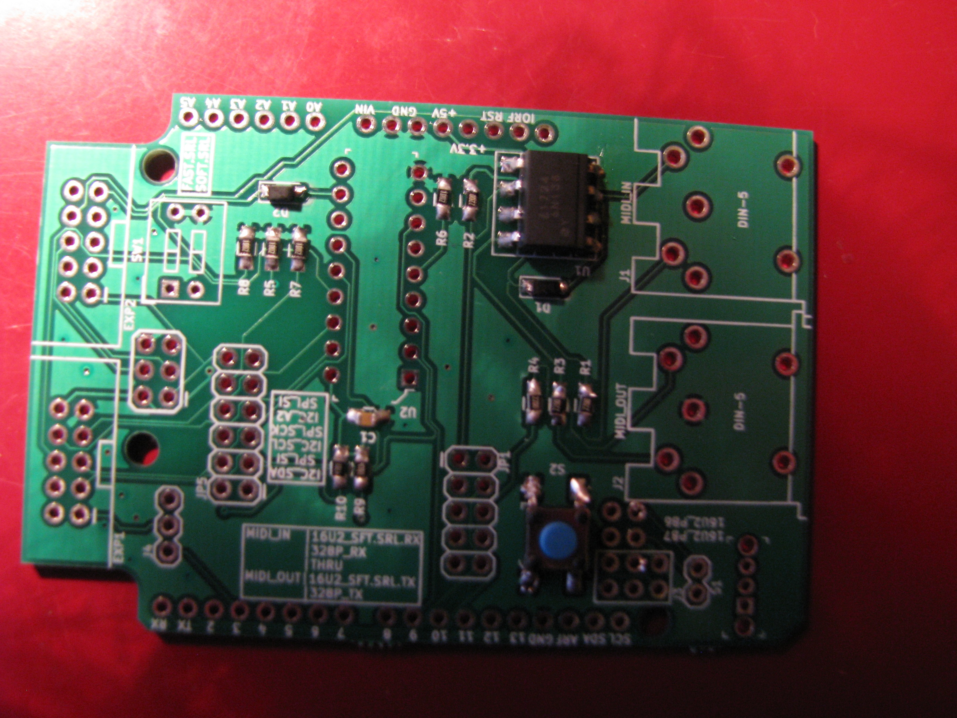
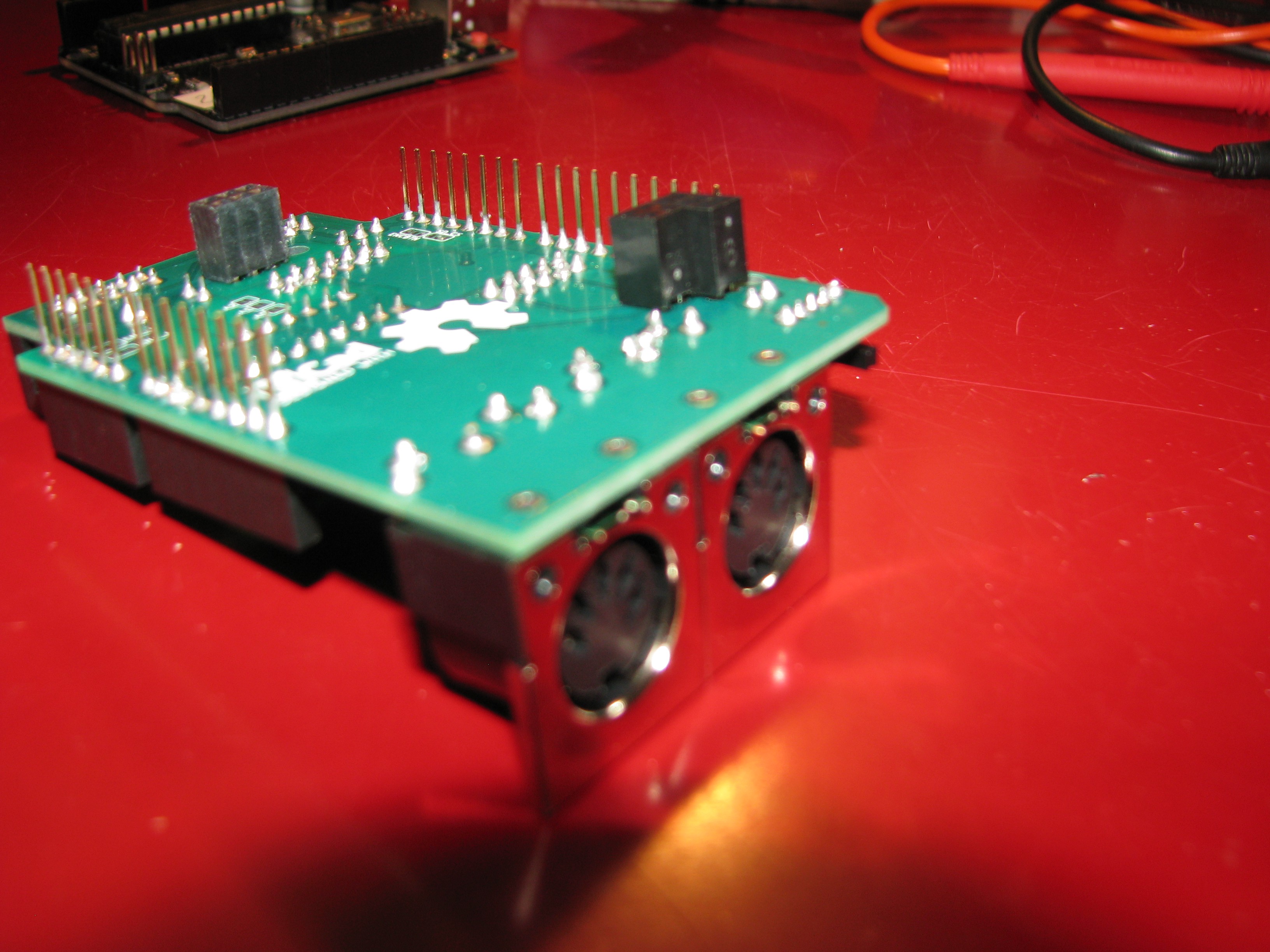
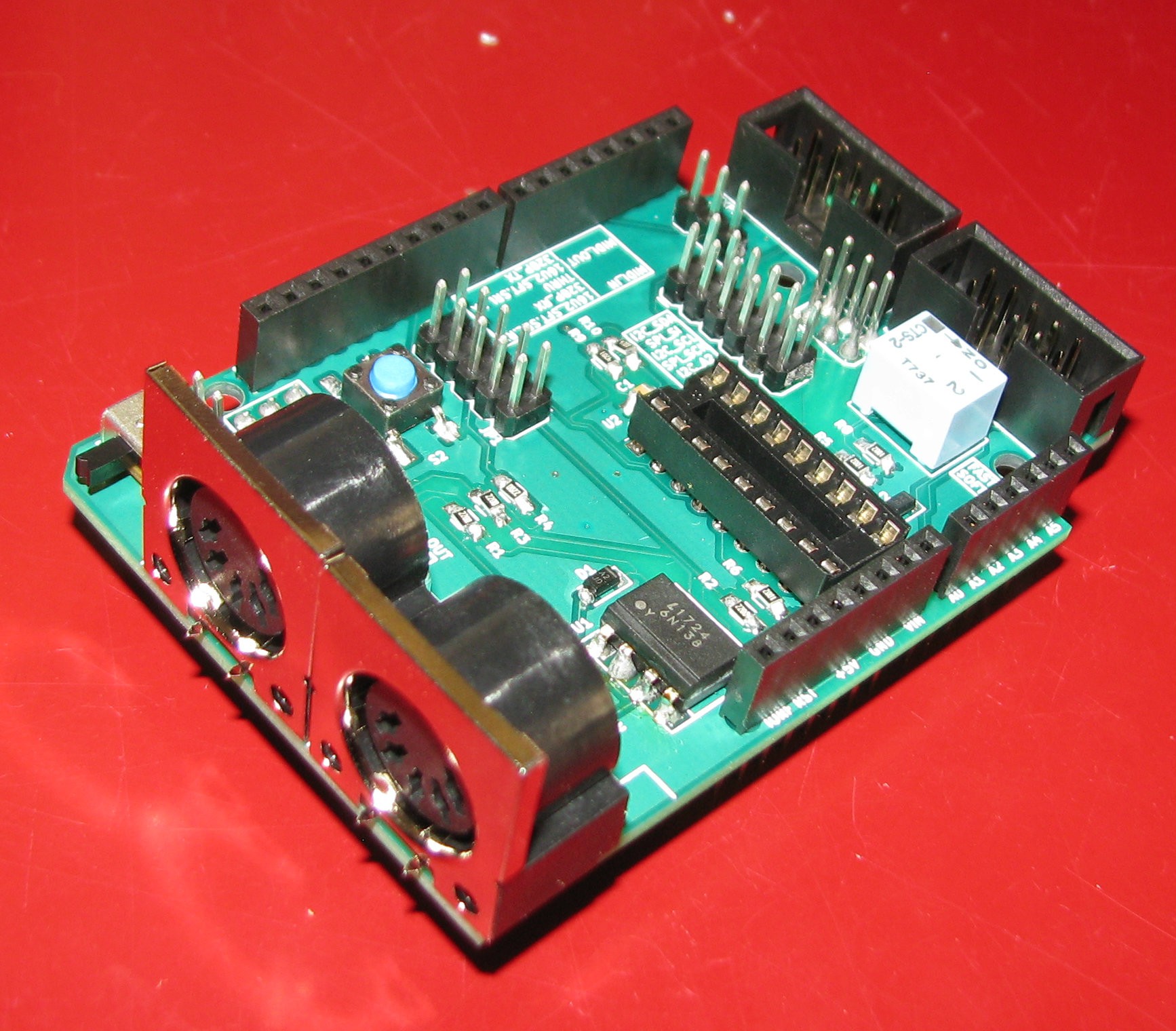
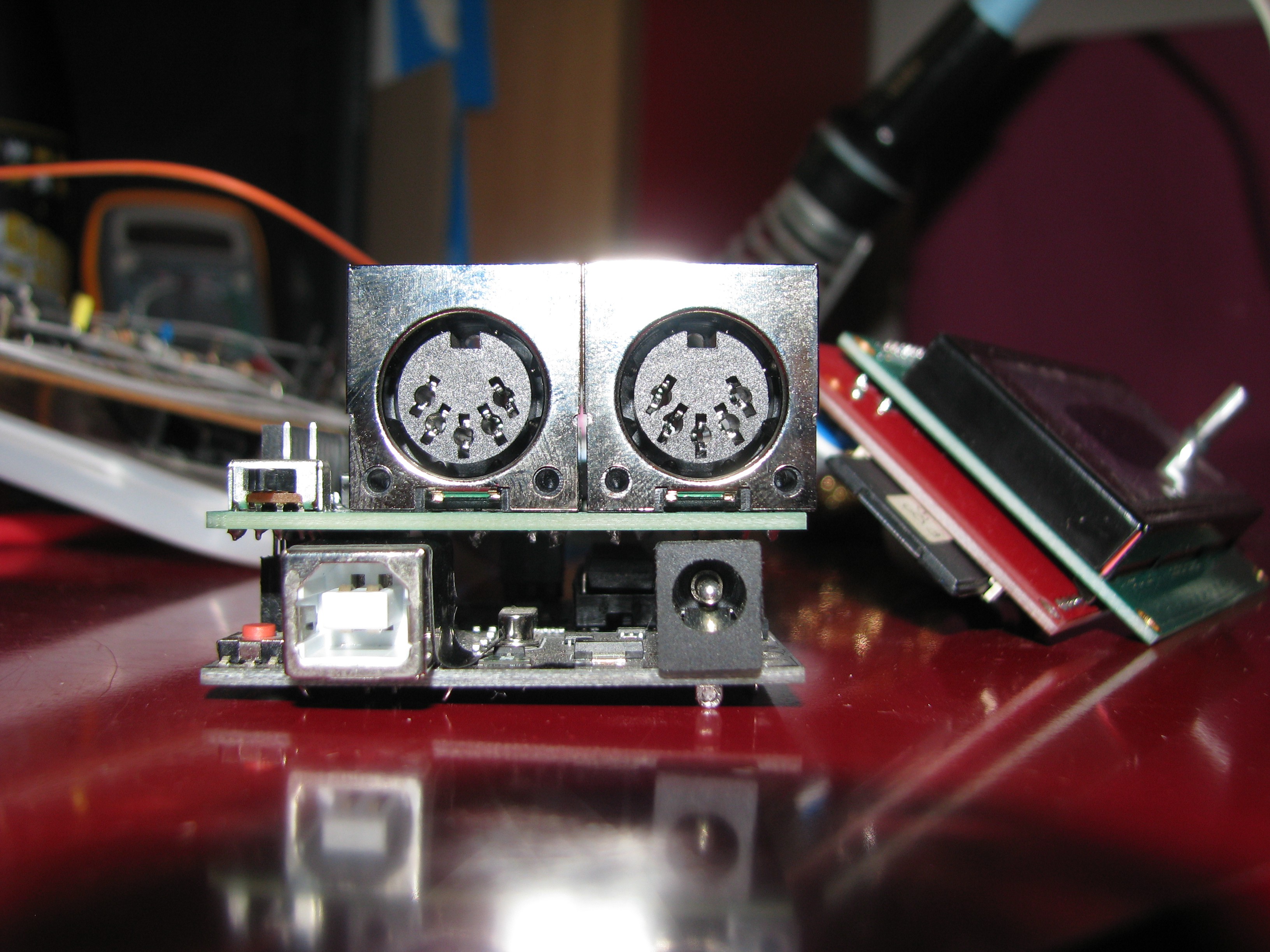
You can probably see in the picture above that the optoisolator doesn't sit quite right. I should have thought of this when I used ready made footprints. the same thing goes for the DIN-5 jacks, as you'll see in the next pictures. I used a ready made footprint since that was easier, then got a different part from DigiKey. That's not that bad, but I should have checked beforehand.
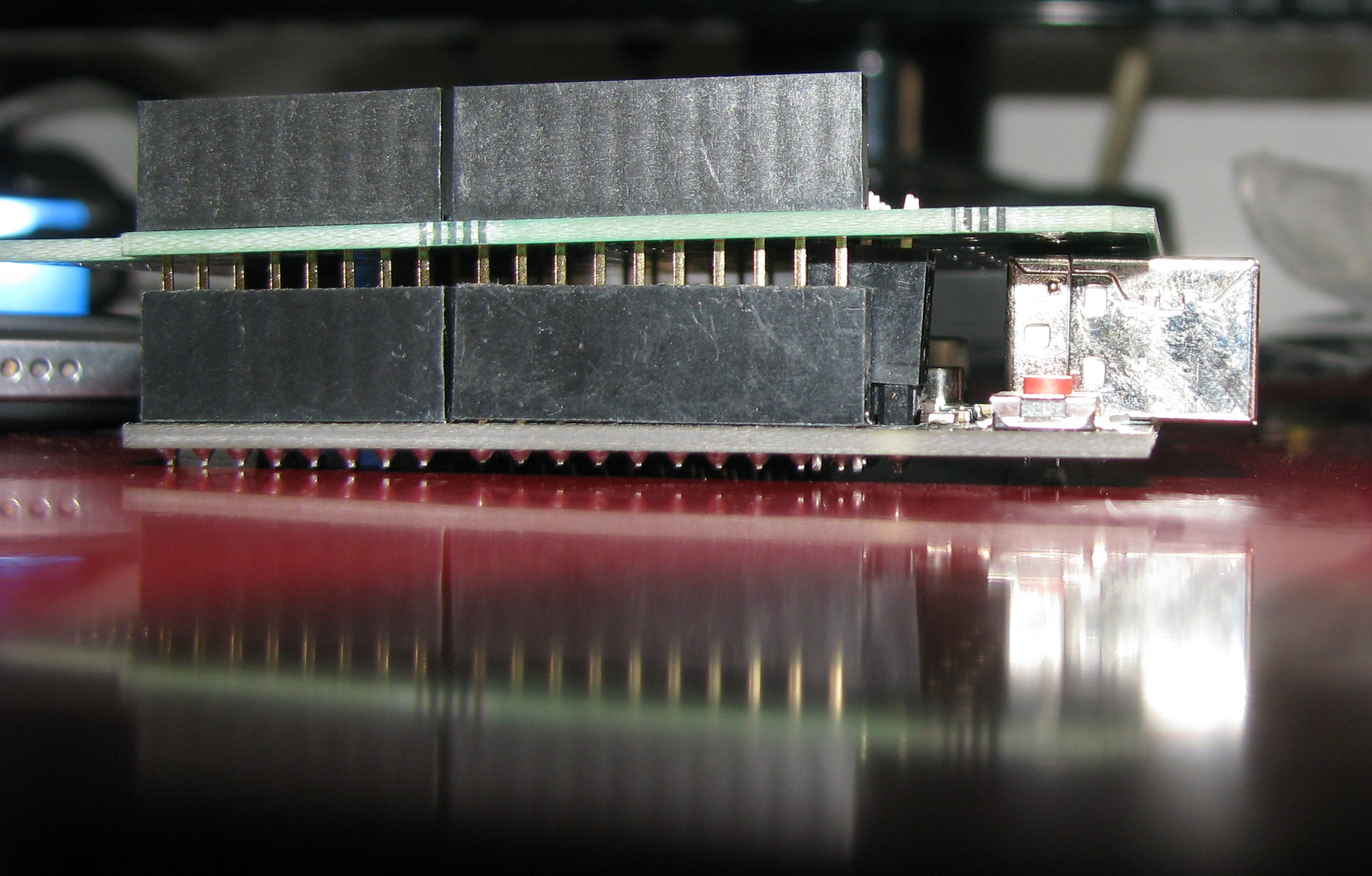
I also got a bit of a misalignment on the Atmega16u2 ICSP. Slanting the 2x headers a bit solved that. The board goes in and out as any other shield.
I started testing the board, but couldn't get the LCD to run. The encoder works, and I still have to do some testing on the SD and buzzer. I'll carry on with testing the LCD with both the MCP23008 & MCP23s08 tomorrow, and hopefully get the screen running so that I can go on with designing block in Ardublock.
Discussions
Become a Hackaday.io Member
Create an account to leave a comment. Already have an account? Log In.