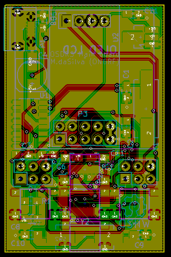
Sooo... First thing I need to design is the main board. It contains:
- The ATMega328, with the appropriate crystals;
- A USB to serial converter;
- The actual radio module;
- A small display;
- Buttons!
- Supporting hardware for all this stuff (regulators, decoupling caps, crystals, etc.).
It's your average Arduino-thingy board, the design process is quite straightforward.

Small note regarding the RF part: I added all the supporting hardware for the CC1101 on this schematic: the balun system plus all the filters for the 433MHz band. However, I am not going to add this section to the first version: it is my first SMD design, I don't want to add the complexity of RF to this design for now (plus the QFN-20 package is tiny!). I'll use some ready-made modules that will be soldered though a header for now.
I added 6-pin header for the future PA board; I brought out two IO pins from the µcontroller, 5V and 3.3V power, and ground. RF won't be going through there, I'd rather connect the PA and the radio module through some piece of coax.

I tried to fit everything onto a 5x3cm board. Phew. Lots of vias, and some traces take a long way to connect one point to another; I'm a bit worried about the USB lines and the crystal for the USB to serial converter, they seem a bit long to me.
Meh, I'll send it to the fabhouse and see how it goes! Worst case scenario, I'll learn something along the way :)
 M.daSilva
Discussions
Become a Hackaday.io Member
Create an account to leave a comment. Already have an account? Log In.