Chuck Glasser
-
One mans junk is anothers diamond in the rough!
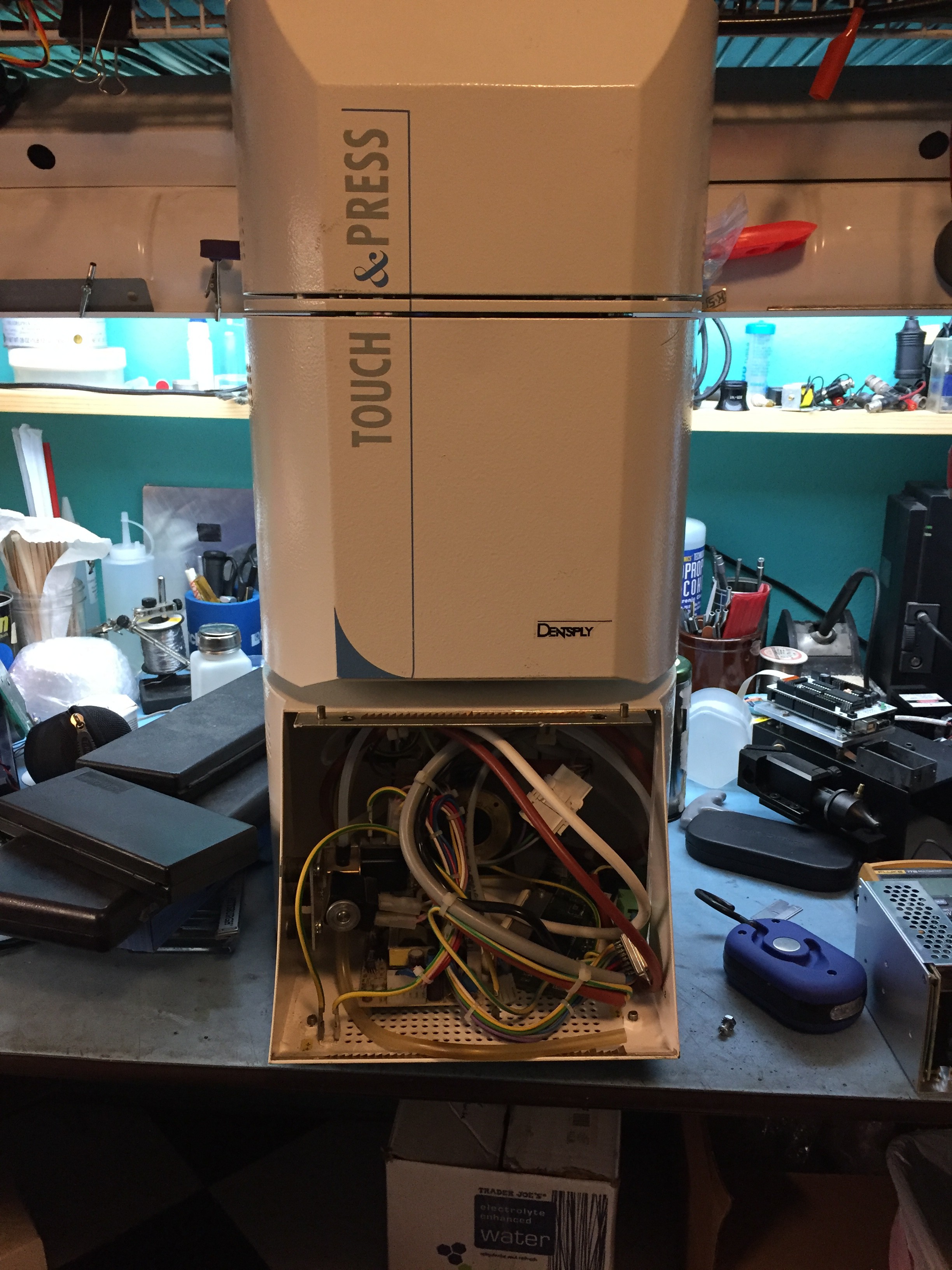
10/16/2016 at 07:13 • 0 commentsJust a few days ago I awoke with the thought that I needed to check Ebay for bargins: It didn't take long to find it.
One of the realities of dealing with all ceramics is that they shrink when fired. That is especially critical when there are many layers with carefully placed traces and vias interconnecting the various layers.
In general there are three methods to control shrinkage. Each method tries to minimize shrinkage in the X and Y axis and confine material changes to the Z axis.
Heraeus, HL2000 "zero shrink" tape is made up of uniformly sized grains of material say 8 to 12 microns. This methods gives a shrink factor of much less than 1% in the X & Y whereas the Z may change by %20, whereas one might expect to find 15% in X & Y with ordinary tape in which the particles are whatever came out of the ball mill. The second method is constrained sintering in which the green tape is glued to an alumina substrate and fired. Electro Science Laboratories provides materials for this method. The third method places a weight upon the surface of the tape while it is fired. That is what this pressing furnace is designed for.
![]()
You can probably guess why it was such a great bargin! No matter. An ATMega or Beaglebone Black, display, a few relays and sensors should make it right in no time.
-
There is great rejoicing in the village, Persius has slain the dragon!
10/07/2016 at 19:14 • 0 comments![]() Before your eyes is the weapon that slew the dragon! A little nicked from the hard bones. Four layers of tape with really thick, "too thick", silver ink. The circuit layout used 5 mil design rules. Most of the components are 0201 size.
Before your eyes is the weapon that slew the dragon! A little nicked from the hard bones. Four layers of tape with really thick, "too thick", silver ink. The circuit layout used 5 mil design rules. Most of the components are 0201 size. From here on, it's practice, practice, practice, and lots of process development.
-
The hard parts
09/23/2016 at 05:58 • 0 commentsAfter the ceramic green tape is blanked and via punched via a laser, printed with inks, the various layers stacked on a fixture it is necessary to laminate the layers together via the isostatic press.
To laminate the tape, the various stacked layers are placed in a pouch and vacuum sealed. So, I thought to myself, why go to the trouble, "not really that much trouble", of vacuum bagging when I could just manually press the pouch free of most of the air and rely on the extreme pressure of the hydraulics to overcome whatever air is present within the pouch? Wouldn't that be enough? I think the answer is yes. However, there is a problem.
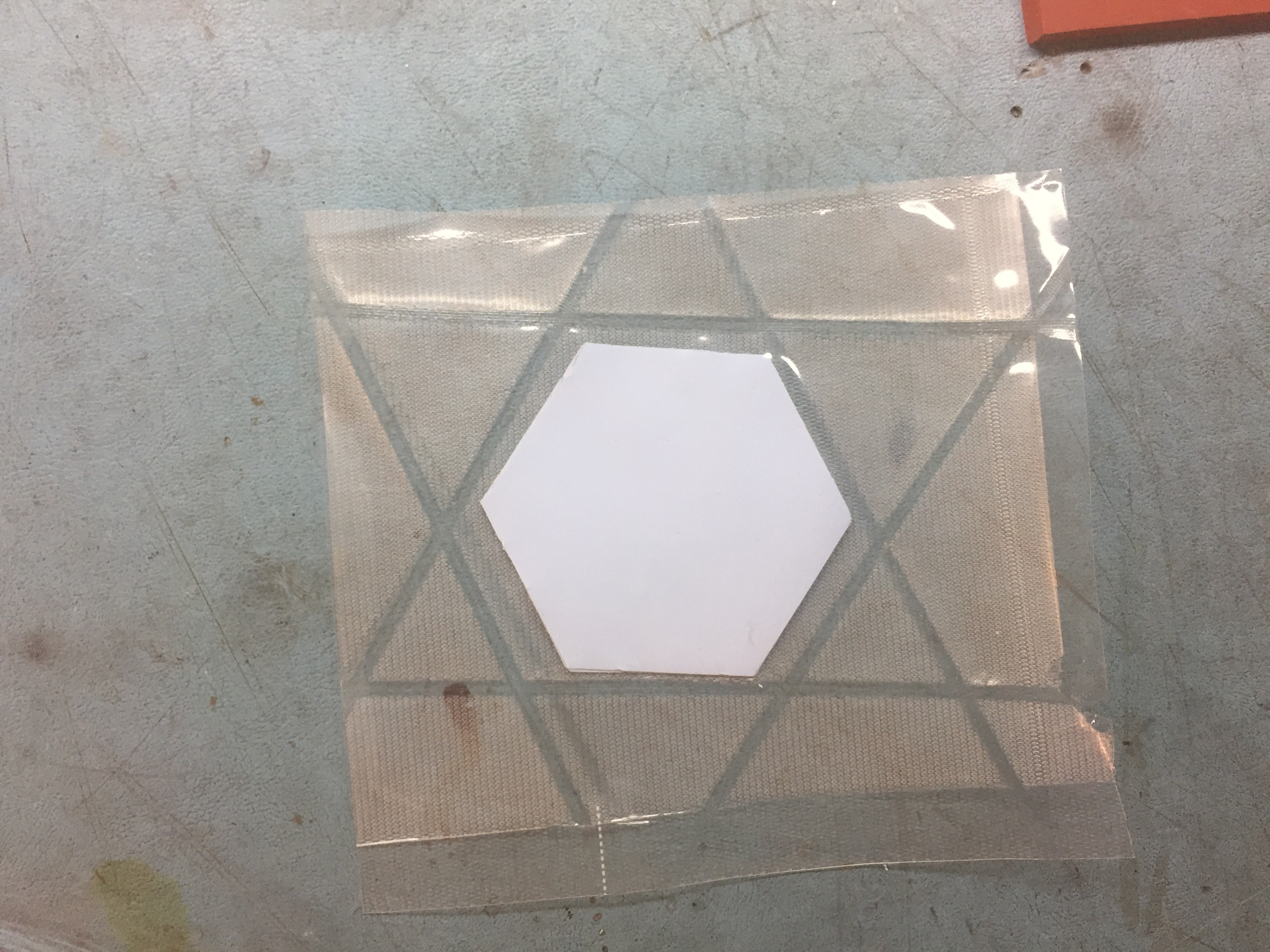
A few layers of tape were cut out using the template at the lower right,
![]()
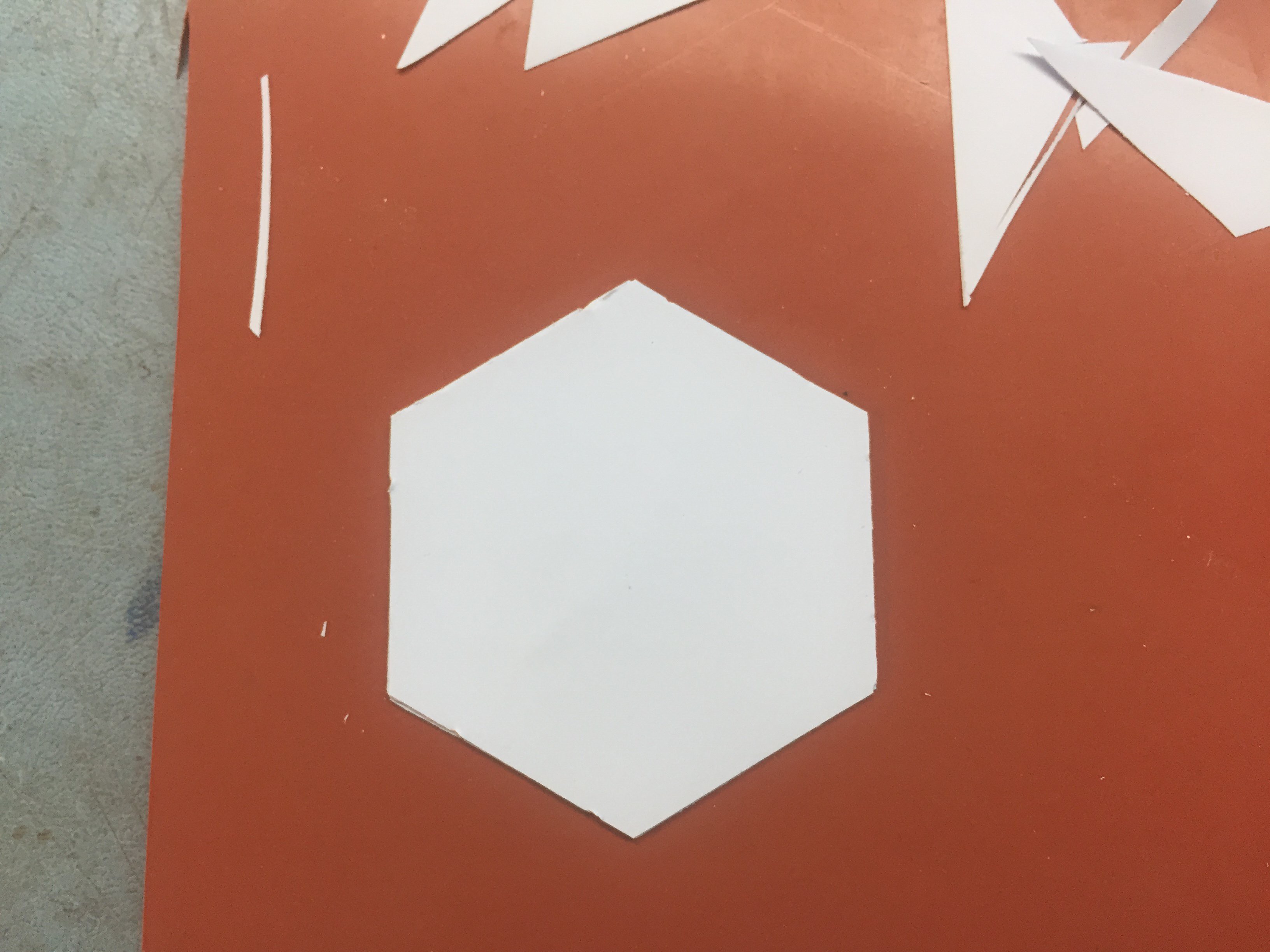
stacked
![]()
and sealed in a bag which was then sealed.
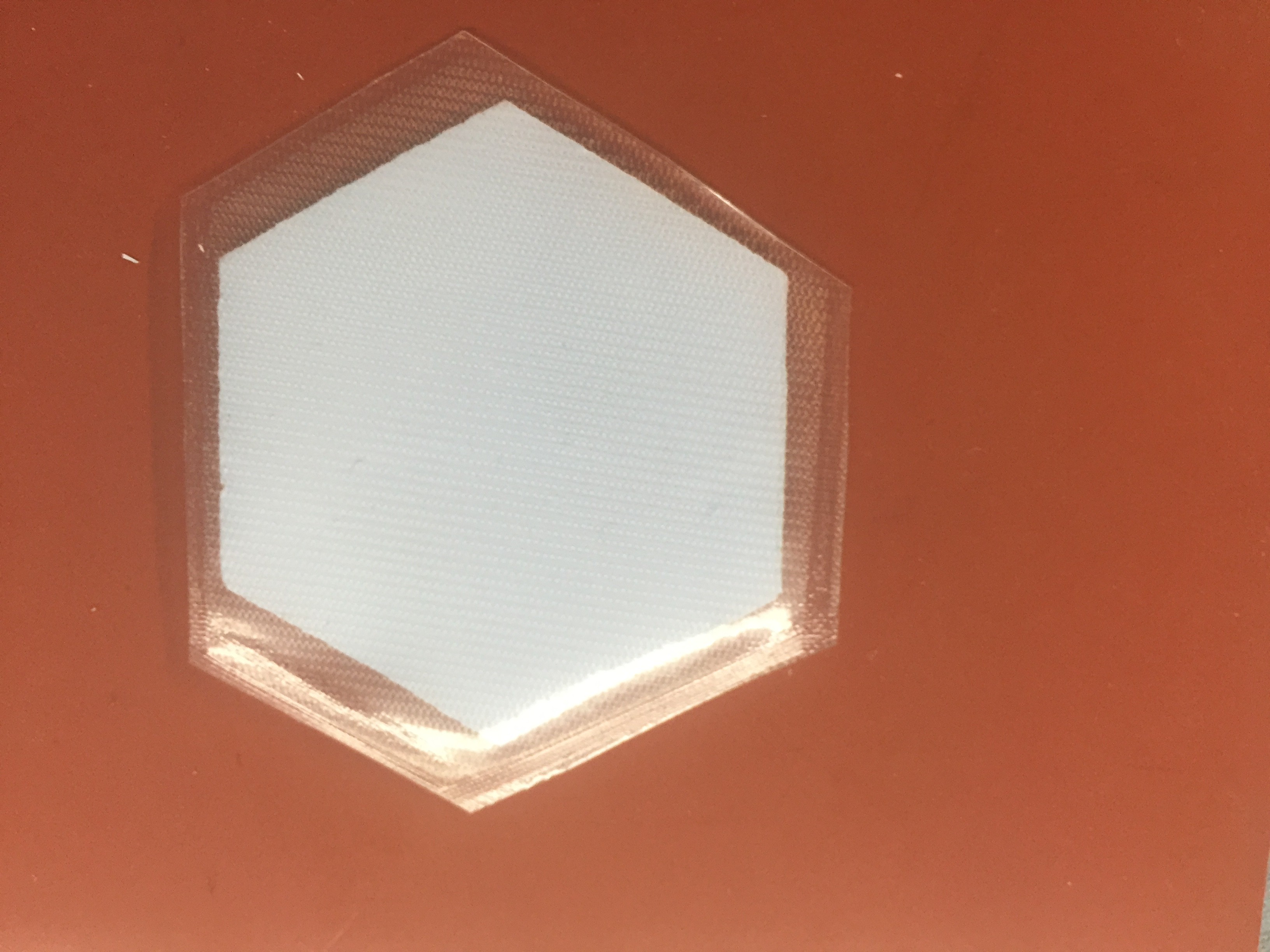
The pouch is trimmed.![]()
The pouch is then placed within the isostatic press![]()
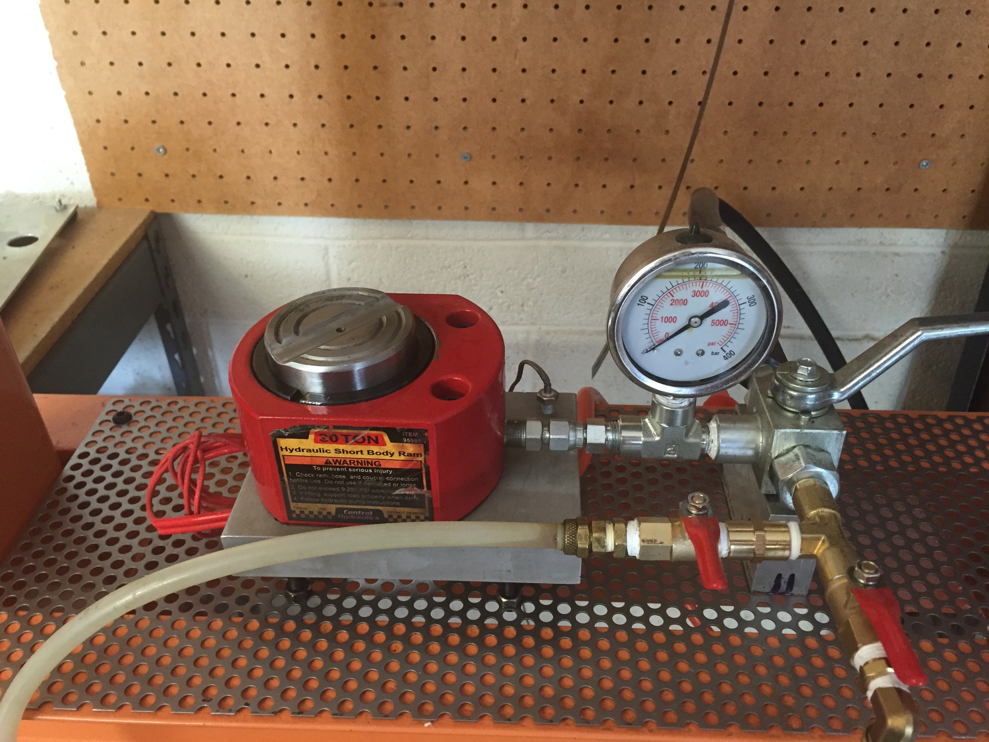
The tape stack is inside the piston cavity along with the hydraulic fluid at 0 PSI and heated to 70 C for a hour or so until everything has had time to get to the pressing temperature.![]()
![]()
Then pressure is applied for around 10 minutes. You can see on the gauge that the pressure is around 4,000 PSI.
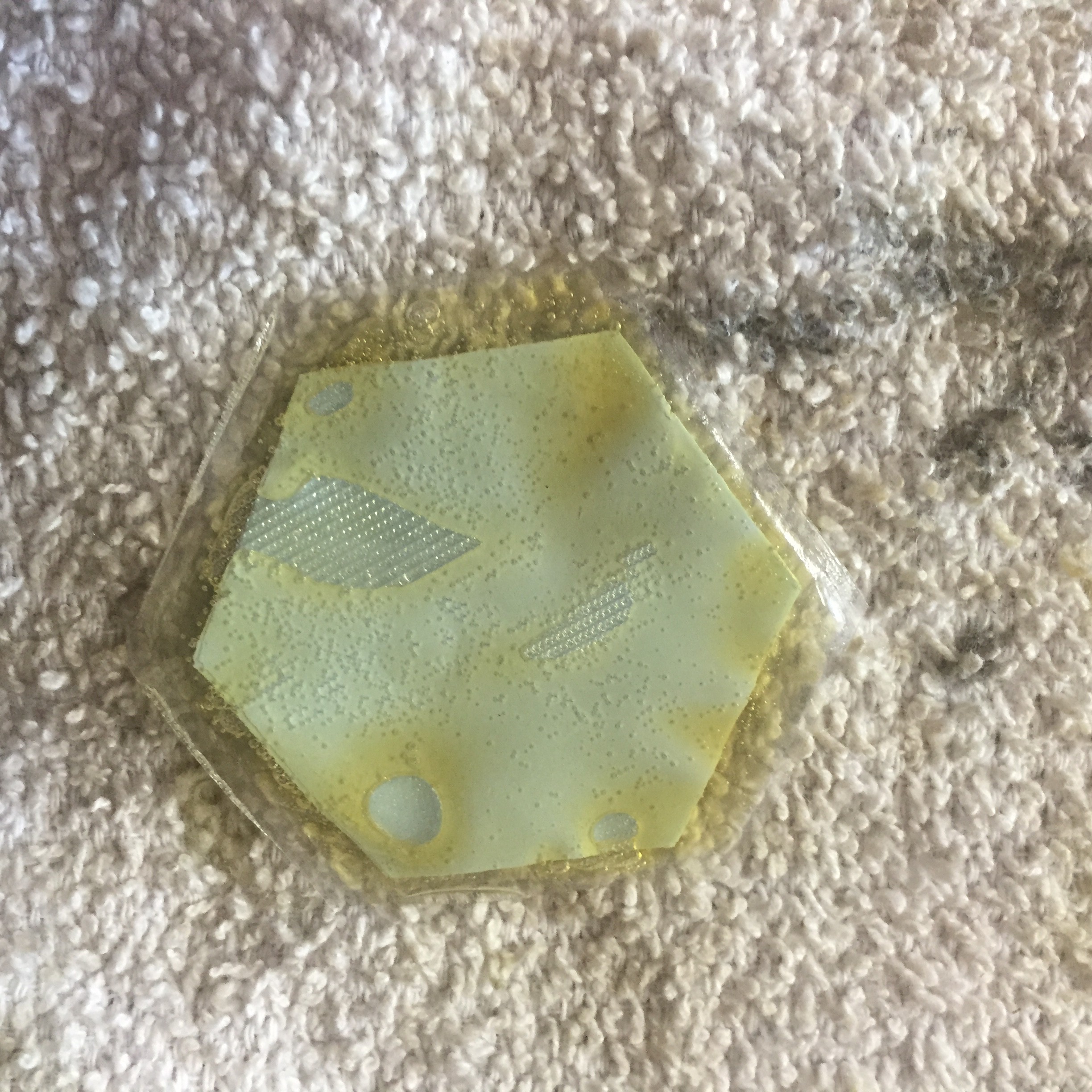
Here is what I found after taking the tape stack out of the press.![]()
![]()
Hydraulic oil in the bag. Dang, and double dang. Note that the tape does not appear flat. That has nothing to do with the failure of the pouch, it just the nature of the details of this step.
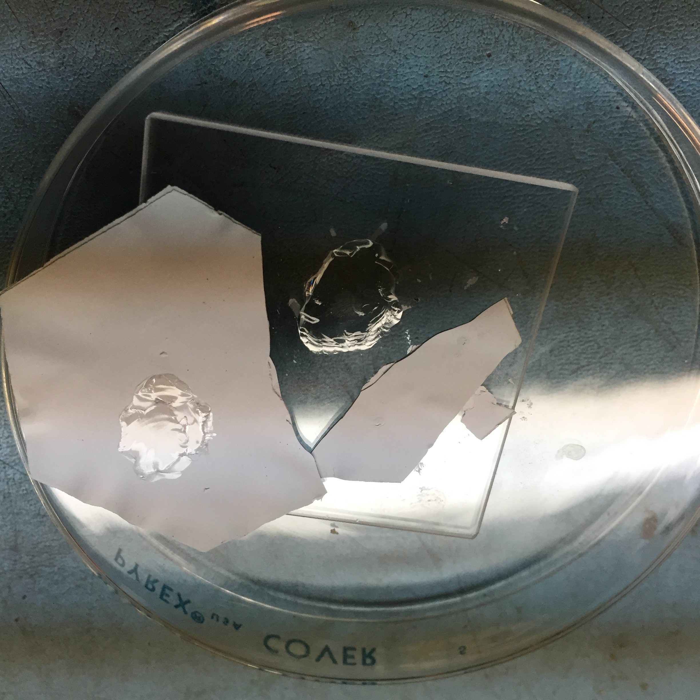
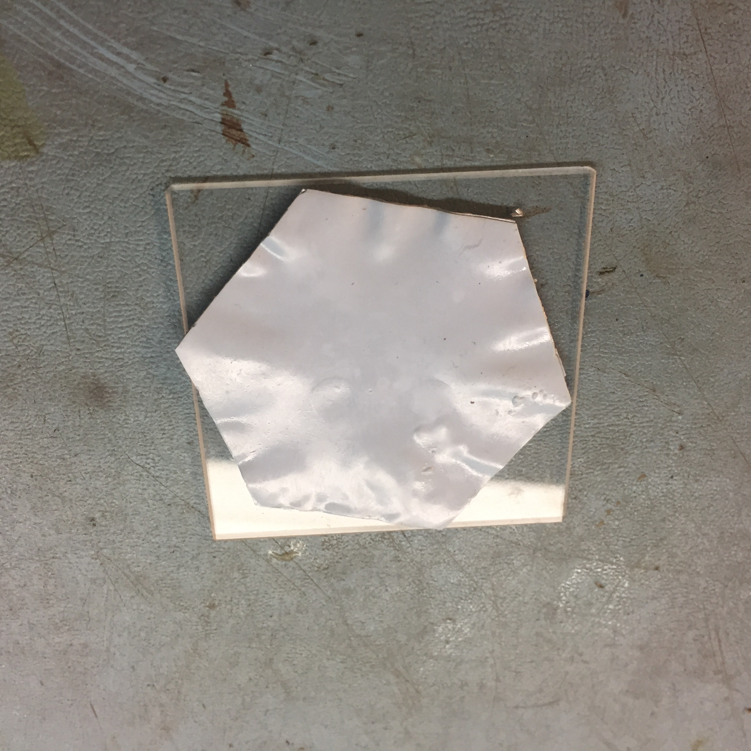
The stack was cleaned with a towel and placed on a quartz substrate. Not even close to being flat!
![]() The tape stack was fired anyway.
The tape stack was fired anyway.![]() You'll note that the quartz fused to the tape. That's a surprise! More importantly, note that the tape did not flatten out under the influence of of the firing temperature of 850 C.
You'll note that the quartz fused to the tape. That's a surprise! More importantly, note that the tape did not flatten out under the influence of of the firing temperature of 850 C.
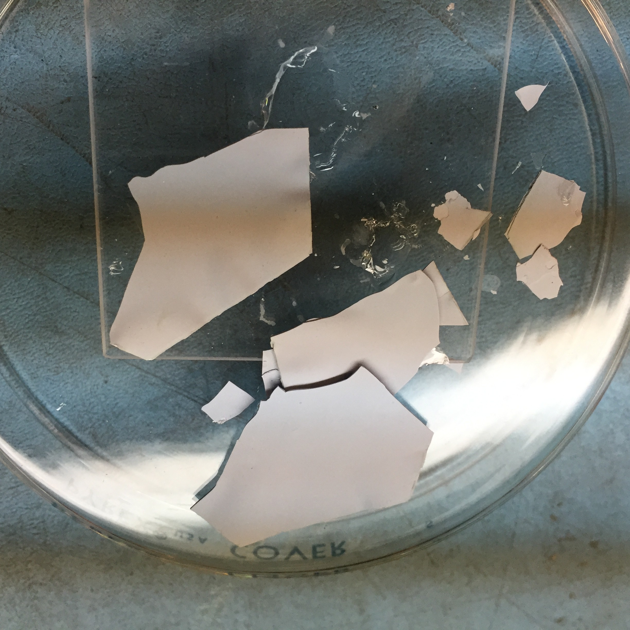
Brittle, fragile, useless junk!![]()
Oh, what to do?
Fundamentally, the reason for vacuum bagging the contents is that a bag that has a good seal is visibly different than one that has a leak. Now I know.
Alumina, Al2O3, otherwise know as aluminum oxide is a fundamental industrial material. Almost as hard as diamond. Very, very refractory! In one of it's many forms it comes in sheets. Very flat sheets. Along with making up 50% of composition of the LTCC green tape.
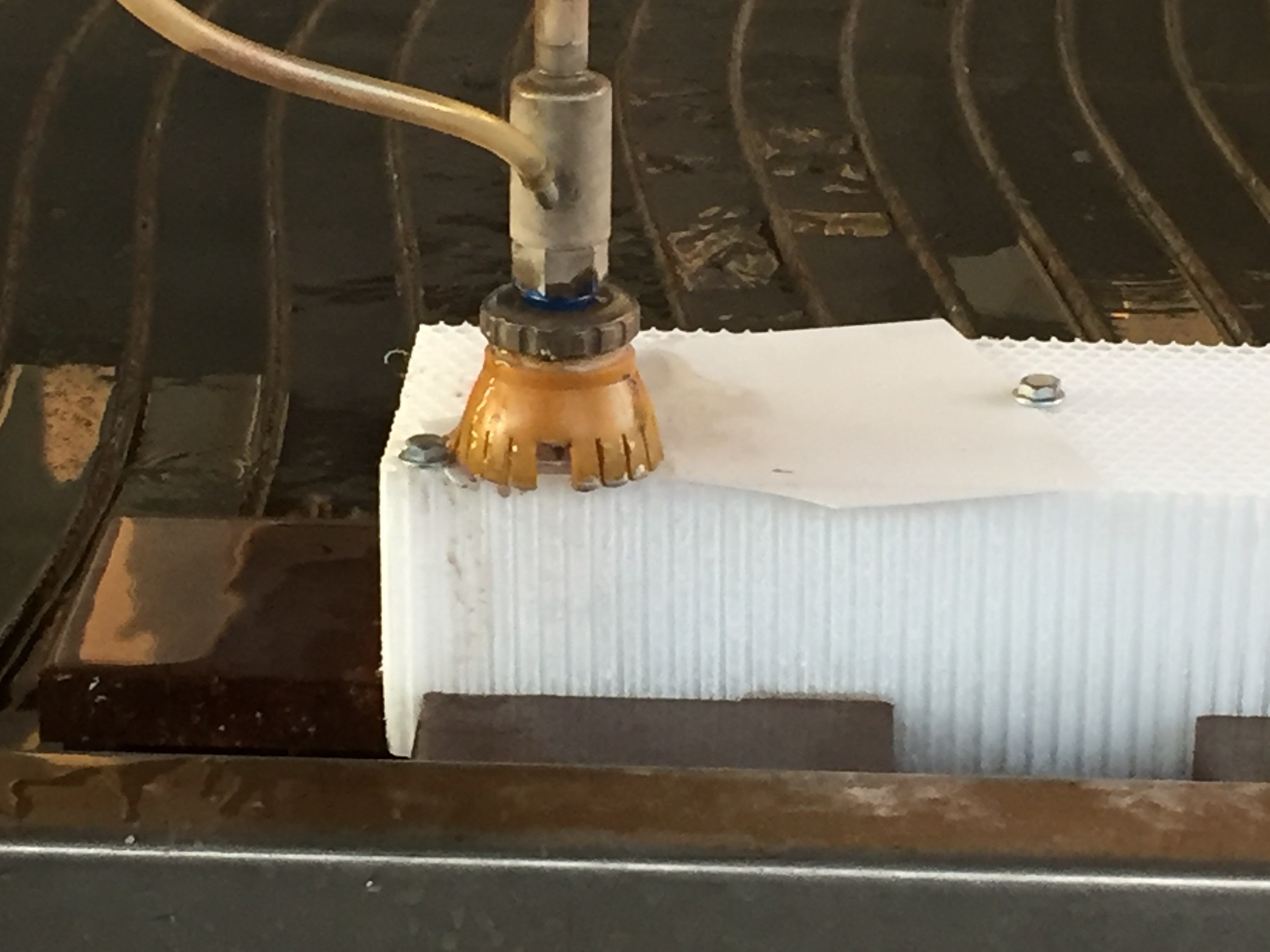
Considering the materials extreme hardness, how exactly is it conveniently cut?
![]()
The waterjet works brilliantly! It takes about 55 seconds to cut a 25 mil thick plate with a 2.25" circle.
-
Registration
09/07/2016 at 06:01 • 0 commentsSo the essential detail in building a system that can produce working circuits with 3 mil design rules is keeping all the various processes registered. That means that if a hole is laser drilled at X = 3.455685, Y = 5.343366, and later come back to via fill that hole, the fill operation is at the same coordinate, and so on.
That means that any artwork needs to be made in such a way that lines of ink end up the same way. Always located at a precise location corresponding to all the other precise locations. In other words, all the various processes have the same reference point.
What this means is that even though the ink jet printer may not be used to print silver ink, it serves very well as part of the mask making process for the screen printer.
![]()
To review, there are only 6 operations in making a LTCC circuit.
Blanking, via filling, circuit printing, stacking, pressing, and firing.
For blanking either a CO2 or 455nm laser may be used, or a drag knife, and/or a hot drag knife. For minimal residue, a knife seems best. For holes, pulsed laser.
For vias and lines we'll use a screen.
The screens will be made by first printing a registered transparency onto the vacuum table. The Ink jet is used to print the pattern.
A registered screen is then place on top of the transparency and the artwork is exposed from below or more practically, simply removing the transparency and registering it to the screen frame.
The key is that everything is registered to a set of pins on the CNC table. Tape, artwork, screen printing frame, laser, camera, cutters, etc.
In this case the 6 holes at each of the hexagon apexes will be used.
-
It's a horse race
09/05/2016 at 04:02 • 0 commentsI've just posted a production order form DirtyPCBs for my ADS1299 amplifiers. Pay for the DHL services and you'll have your boards in no time!
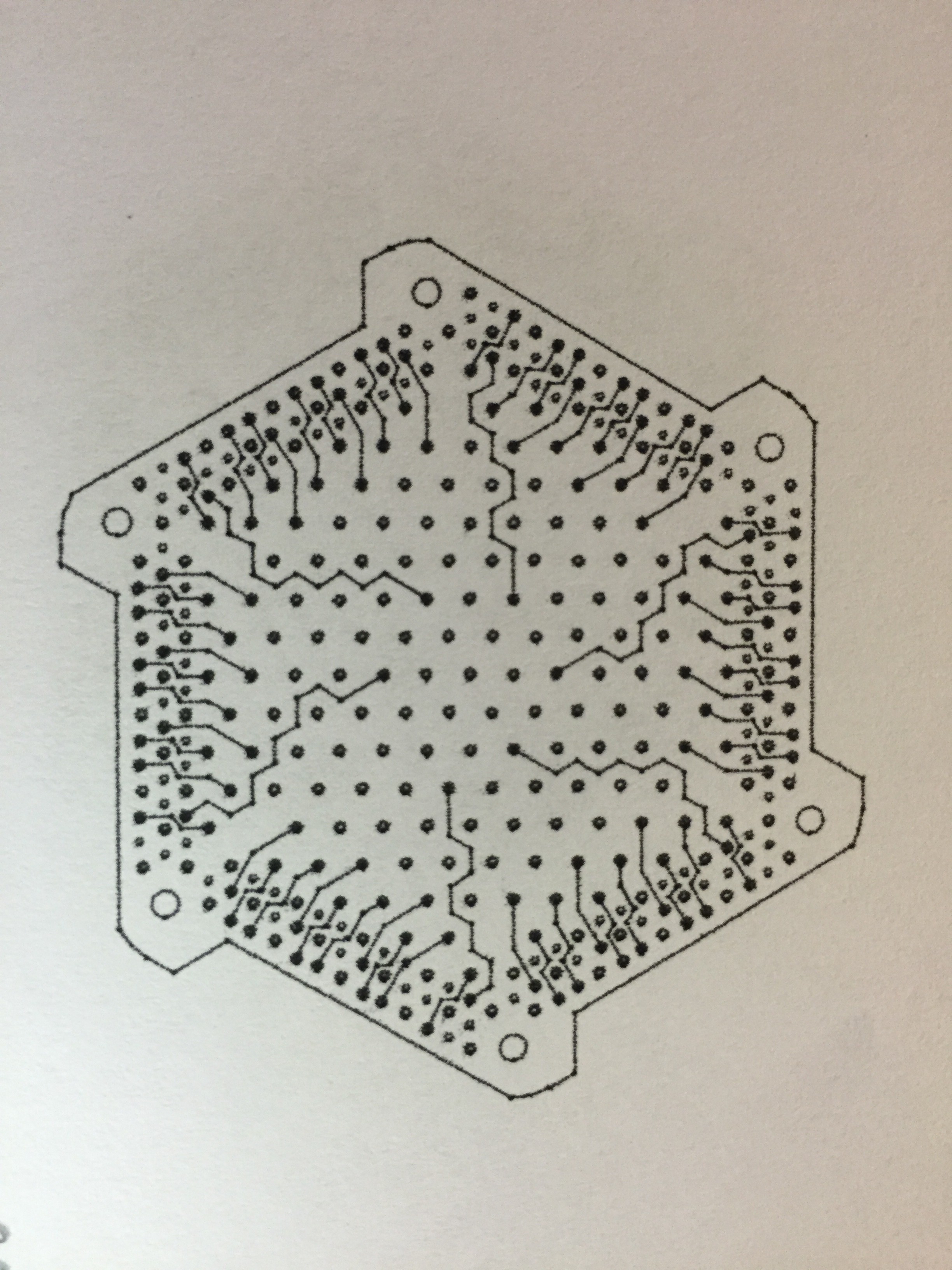
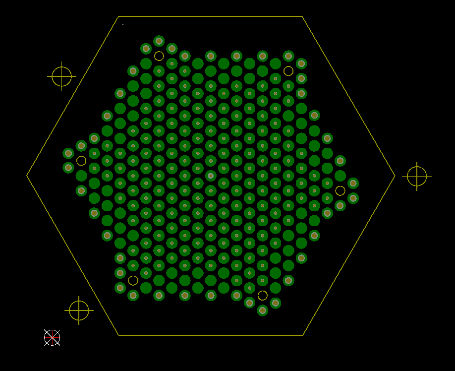
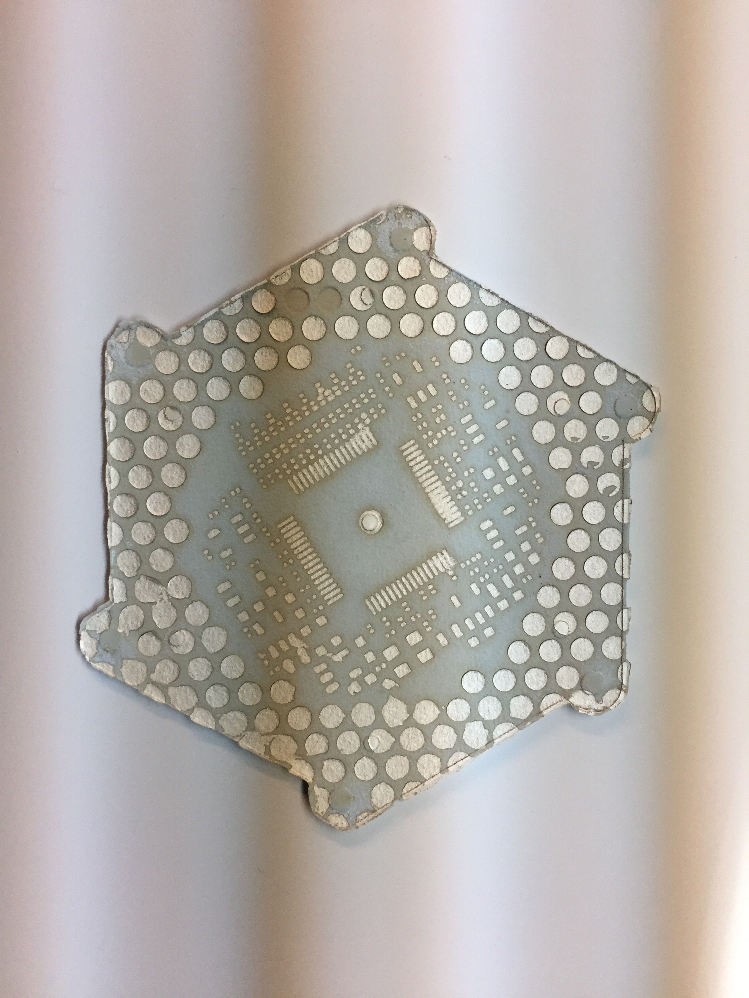
So I need to make some electrodes that mate up to this pattern.
![]()
Seems simple enough. Only a few pads are active (12), but which ones? The other pads are placed to preserve planarity.
-
A new press !
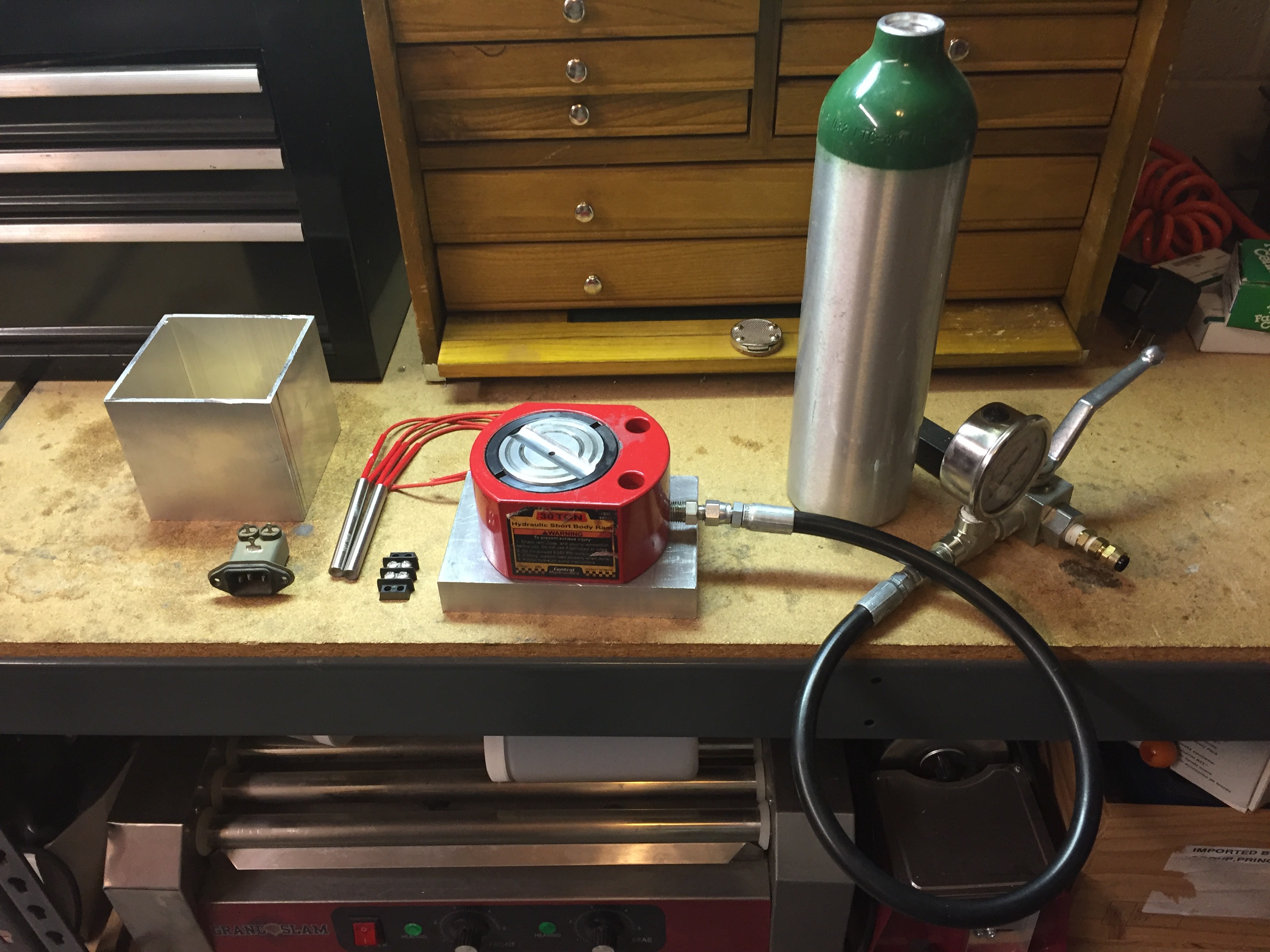
08/01/2016 at 02:45 • 0 commentsThis project didn't start off with a big huge press. Time to go back to basics. I had started off with this Short Jack, 1/2" of lift rated at 9,250 psi, with a piston 3" in diameter. Actually perfect for my needs.
![]()
When I initially tried to change the hydraulic fitting it only stripped in the socket wrench that was perfectly sized. So, I got frustrated, and lost interest. Better to spend tons of money, and time on a boondoggle.
With the big press down for some considerable time, and needing to move forward, I took a wrench to the offending fitting and welded it in place. The fitting now came off quite easily, with only a bit more torque that would previously strip the fitting. No tool, the wrench, has ever been so enthusiastically destroyed.
Even more important, these jacks are really inexpensive! New parts cost, jack, hoses, fittings, hydraulic pump. Around $250. This seriously improves the odds of overall project success!
Also, of some considerable importance is understanding why it is necessary to use a screen when printing the conductors. The simple answer is that with a screen in place the ink can only go in one direction, Z.
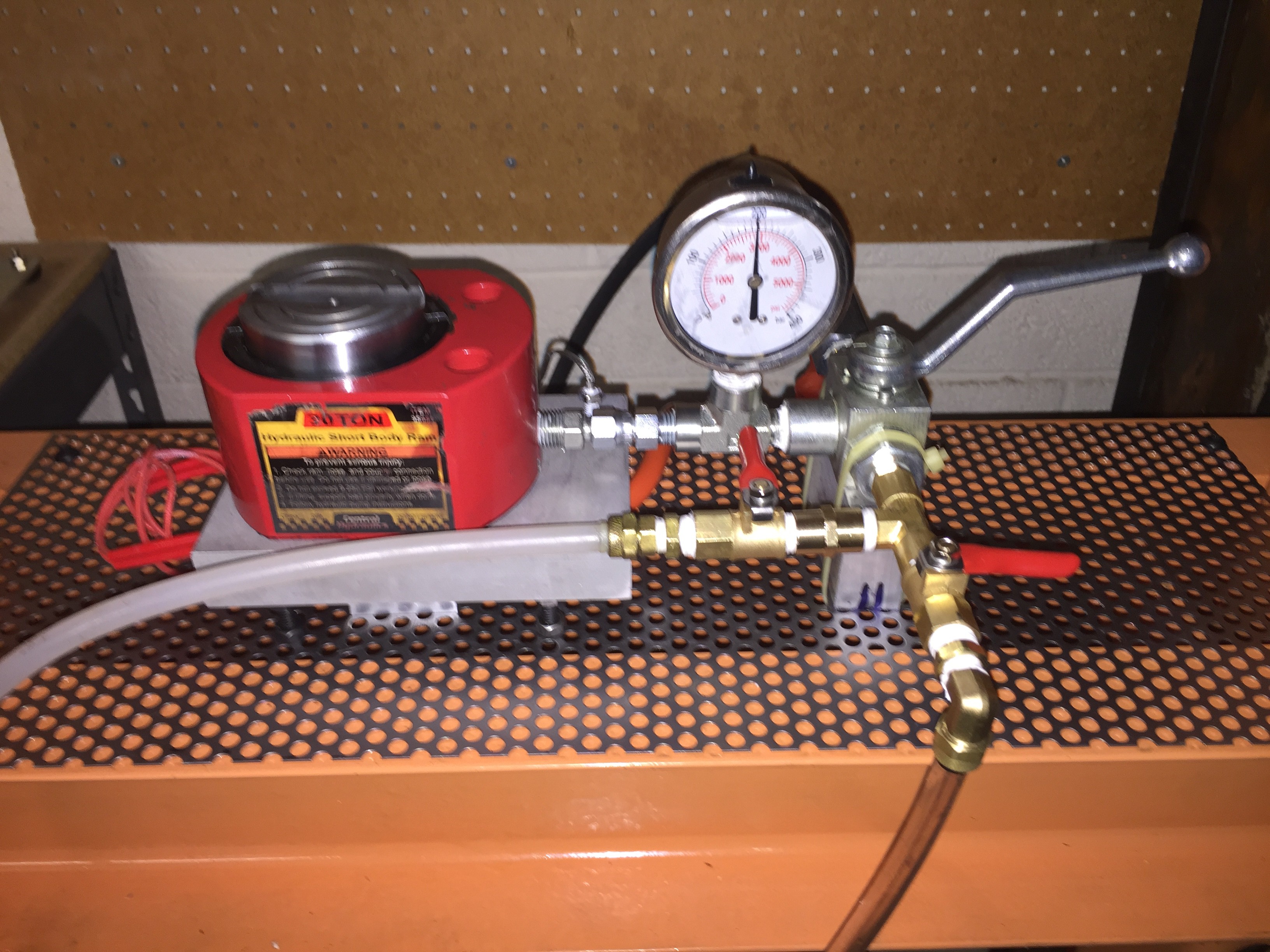
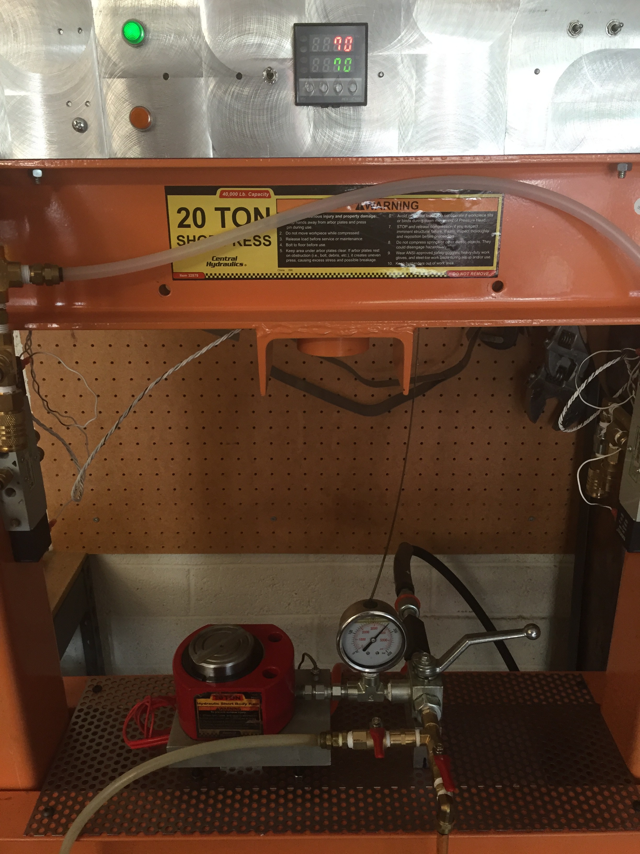
Here's the new press . Isn't it beautiful!
![]()
Nice and clean. So simple. This is my first, and really positive experience, using perforated metal. Now when oil leaks it will simply drip through onto the drip pan below.
You'll note that the pressure gauge indicates 3000 psi. Oh happy day!
There are three valves visible. The silver handle sources the piston to the hydraulic pump via a check valve. The check valve allows the chamber to be pressurized without the pump running. Very important.
If the silver handle is thrown in the other direction then the chamber releases the fluid to the low pressure side and will flow back into a reservoir where it may be filtered and returned to the pump. One line goes to the bottom of the reservoir and supplies oil, the other is at the top of the tank and provides air. So by pressurizing the reservoir with low pressure air either air or oil may be forced into the piston, or my manually pressing on the piston push hot oil out of the chamber and refill it with air to retrieve the sample.
![]()
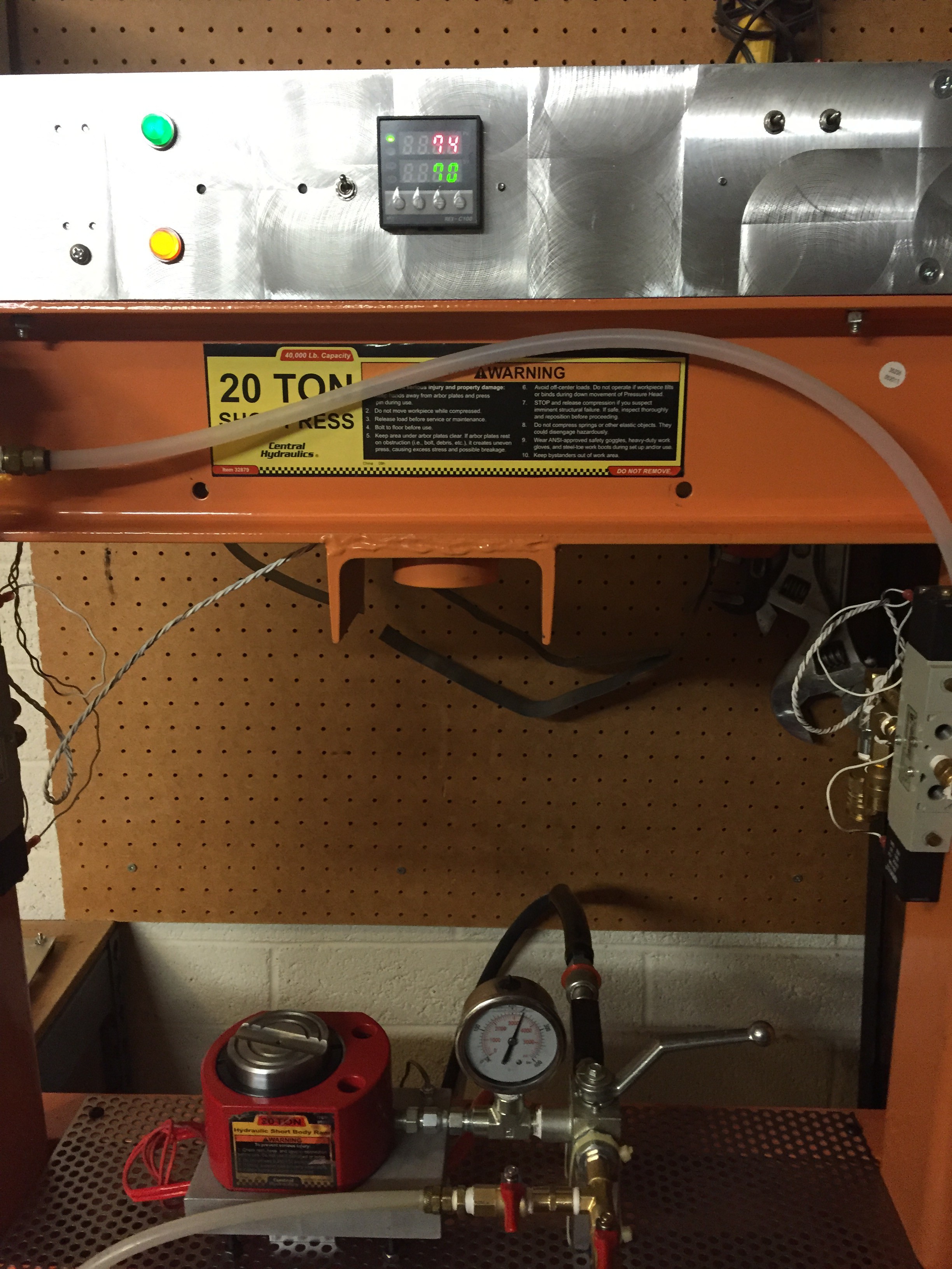
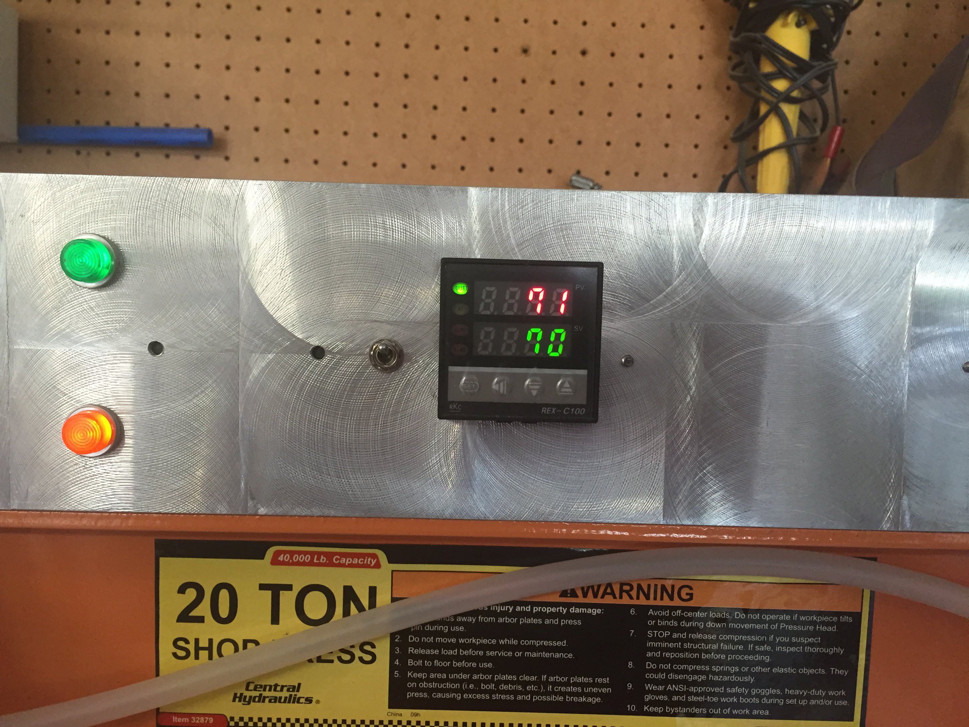
In this image we see the heater block running and the system at pressure.
The industry standard seems to be 3000 psi at 70 C for 10 minutes. That's a big block of material, with the thermal sensor located in the top right corner of the gray aluminium block. As it turns out if the system is pressurized to the working pressure of 3000 psi and the pump shut off, then the check valve will maintain pressure in the line. Thanks to Boyle's law, any subsequent increase in pressure is due to a change in temperature. When the pressure stops going up, in this case by almost 1200 psi, we know the fluid and sample have reached the desired goal.
Other than a few more sea trials to check for leaks I think we can safely put this one to bed! Isostatic press, done! Most importantly, done safely!
-
Never tell your wife you took a shower in hydraulic oil!
07/08/2016 at 01:55 • 0 commentsTwice.
If you look at the big orange machine and study it a bit you will see that the top hydraulic cylinder applies the clamping force at one point. The image of course being that the force holding the top seal in place is along the centerline of the hydraulic cylinder.
After taking several showers in hydraulic fluid as the seal gives way I can guarantee that the clamping force is nowhere near the centerline of the cylinder. In fact the present clamping mechanism is a disaster that can NEVER work reliably and SAFELY. So it will have to be rebuilt. Not necessarily much bigger, but certainly a lot smarter.
I'm thinking a set of 4 linear slides at each corner of the top plate that constrain the movement of the top cylinder cap for movement in ONLY the Z axis.
There are other issues. When the top cap is lowered into place to form a seal it is under no load. Then, as the pressure is raised, the load that was in place to hold the top and bottom in place is reduced.
To be truthful, it's a bit scary! Two hydraulic pumps going chuga, chuga, big "I beams" bending. You know, just your ordinary day at the mill.
So, once the top cap goes on, it needs to be preloaded such that it never moves.
On the ceramic green tape processing here is what I've found.
Green tape, the ceramic tape before it is fired comes from the supplier on a mylar carrier film. The tape itself may be supplied in various thickness fro 1 to 10 mils. In my case the tape is 5 mils thick. It has the mechanical properties and tear resistance of wet tissue paper. When the CO2 laser hits the material it chars and fuses to the carrier that may have also burned away, or not. The material itself is far cleaner when a shield gas such as Argon is used.
If I had my own formulation of binders I would use acrylics as they are know to sublime without residue, but I don't and so I'll have to adapt to the needs of the materials I have.
After laser cutting the tape is stuck to the carrier film. If the carrier is removed and the tape cut directly on the backing plate, today I used a ceramic kiln support plate 7" on a side square, the tape will be stuck to the support.
It's looking very muck like a cutting plotter and a via punch should be two of the stations on the large bed CNC machine!!!
It is essential that the blanking and punching operations not produce a situation that will later induce an operation that will change the dimensional properties of the tape. This is not presently the case. So, while slipping a sharp edge spatula between the tape and carrier may seem like progress, it really isn't.
Registration of the multiple layers of tape requires a fixture. Experiments suggest that staking the various layers onto a platen press with registration pins may be a good solution as alignment and pre pressing in a platen press may keep the layers together sufficiently for later pressing in the isostatic press.
-
The gods of electrons must be looking after me
07/05/2016 at 03:41 • 0 commentsDecades ago I picked up a big drip pan. I have no idea where it came from. It had been stored numerous places over the years, outside in the weeds, in the garage, stacked with lumber. Way to handy to toss, and yet for all the many decades I've had it, it was never used. Until today.
Apparently, when a hydraulic seal is doing it's job, there is a significant friction force. Hundreds of pounds of force in this case, and when the seal is dry, it's even higher. So, I've got the pneumatic cylinders pushing up trying to fill the back side of the piston with salad oil, and gush, as the piston lifts the cylinder off the lower seal, spilling the contents into the drip pan. And there you have it, years of neglect, vindicated. And that's why you should hoard! Save everything. As long as you remember that you have it, it will be there some day to save it.
It should come as no surprise that the press is a very dangerous machine. The pneumatics are especially dangerous as they are extremely fast. Throw the switch and WHAM. Things move very, very, fast. Hundreds of pounds of force. Better not have any body parts in the way!
The leads of the thermocouple were reversed at the controller. Now, when the heaters are powered, the temperature goes up, rather than down, which would be wrong. Got to love those really inexpensive process controllers from China!
The top cap is now suspended by a set of springs that allow a simple placement of the top cap against the cylinder. A set of 4 linear slides would fix the issue, but that would involve a complete disassembly, flow jet water cutter time, several hundred dollars for the linear bearings, etc.. Perhaps later when all the issues are understood.
So apparently, despite my frustration yesterday when everything was going the wrong way, everything pneumatic and hydraulic is working exactly to plan.
DIY Space Grade PCBs
3D print circuits using silver ink and ceramic substrates to make high performance, multilayer, fine line < 3mil, PCBs
 Before your eyes is the weapon that slew the dragon! A little nicked from the hard bones. Four layers of tape with really thick, "too thick", silver ink. The circuit layout used 5 mil design rules. Most of the components are 0201 size.
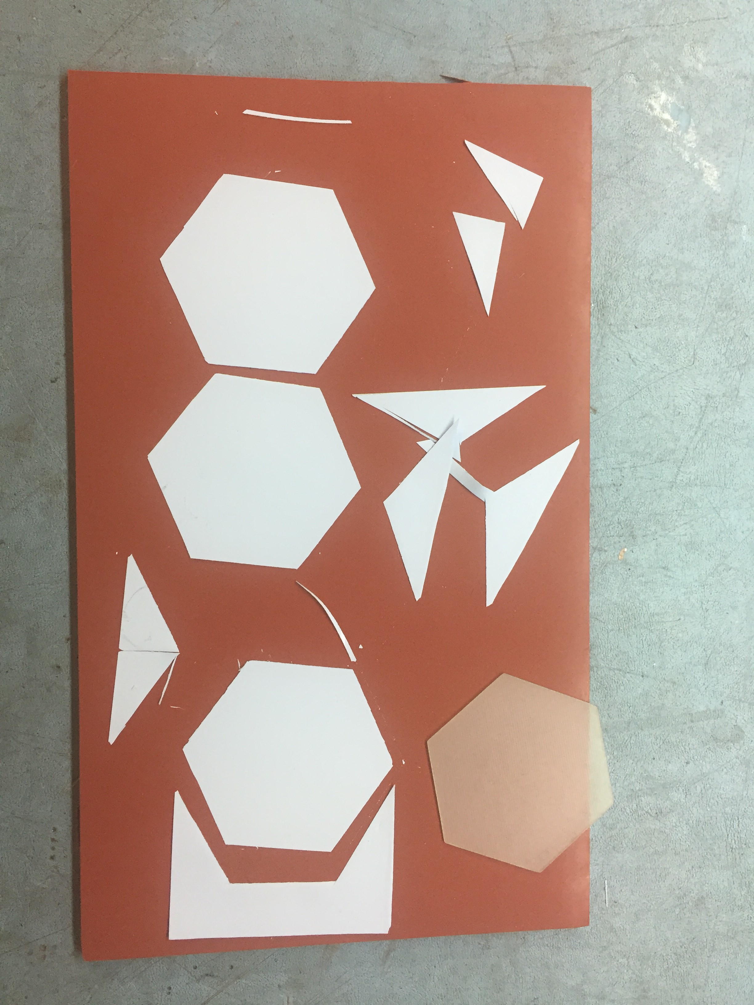
 The tape stack was fired anyway.