Chuck Glasser
-
The importance of small animal sacrifices.
07/04/2016 at 02:16 • 0 commentsToday, it was time to bring up the big orange isostatic press. I had previously drained all the mineral hydraulic oil from the air driven hydraulic pump and it was now time to refill it with an organic Soybean oil. For now I'm using ordinary Soybean oil intended for salads and fries. No point in paying extra for the same thing that is certified to be unfit for human consumption but great for your tractor. I've determined that if there is a leak under hydraulic pressure and I get injected by a hydraulic fluid, the outcome of the disaster will be better if it is organic oil rather than a mineral oil. As it turns out, the oil is not under any constant use as in a machine that is running 24/7 so if my salad oil goes rancid I can just turn it to soap. It's a lot cheaper as well. In any case, I finally came to the conclusion that I didn't need to run down to Harbor Freight to buy a transfer pump when a piece of hose and a syphon would work just as well. The oxygen bottle was filled as well as the pump.
In the LTCC process, the various layers of ceramic green tape are compressed with a hydraulic process to force the multiple layers of materials into a uniform and solid body. The best press to use is an isostatic press as it insures that the material will see a steady and uniform compression force in every direction and across the entire surface of the material. The industry standard for the big squeeze is 70 degrees C for 10 minutes. So, I throw the temperature controller switch up, by convention, up is true, and see that the temperature is moving in exactly the wrong direction. Dang, the polarity of the thermocouple is reversed. Got to fix that!
The hydraulic cylinder has two pneumatic pistons attached whose purpose is to move the hydraulic piston up and down to fill the working volume with hydraulic oil and purge air out of the system. The air cylinders operate under the control a pneumatic single pole, double throw air valves energized by a 24 Volt source. Switch up, hydraulic cylinder goes up, switch down ... hydraulic cylinder goes down. The switch is thrown, and ... nada. The cylinder just sits there, not moving. This can't be. There is an equivalent force of several hundred pounds pressing against the hydraulic piston. Yet, it just sits there. Throw the switch and the machine shudders under the forces, but no movement. Ok, perhaps the piston has sealed itself against the piston wall. I'll force it with an irresistible pressure, say 10,000 psi, the rated pressure of the hydraulic pump. Pump on, nada. No movement, whatsoever.
Hydraulics is a lot harder than I gave it credit.
The purpose of a gauge is to report the process parameters. The secondary purpose it to indicate what the hell is going on when nothing works! There needs to be another pressure gauge at the pump, or perhaps just after the check valve, or two... their cheap!
I was successful in making the piston move once after releasing the clamping force of the heater jacket around the pressure cylinder. But it move once, and then no more.
As if Murphy wasn't completely satisfied, the hydraulic seal on the top cylinder cap has been chewed up from poor alignment as the top plat is lowered down to form a seal.
The GFI tripped. OK after a reset.
Time for a small animal sacrifice. I think I'll make a chicken flat bread pizza.
-
Smoke gets in your eyes
06/28/2016 at 01:17 • 0 commentsIf you go to a hacker space and use a laser cutter, all the magic behind the curtain goes without notice. To get a visceral understanding of what's involved, take a ceramic plate, fill it with wood chips, say a pack of popsicle sticks, pile them high, set it ablaze, right there in the sink. In a few moments, say thirty, you'll have as much smoke as pours out of a laser in the first few milliseconds. To be accurate, it's not the laser that's smoking, it's the workpiece that's in the focal point of a death ray.
So, behind the curtain your going to find a big blower and flue system sucking away your general ignorance.
Wait, there's more! The smoke is different than that you have seen from a flickering campfire late at night. The smoke is more like that from a blow torch, a blast of smoke propelled by a death ray. It's very impressive. Of course, the idea is that the smoke system is effective and the nieve go about their day making their gizmos without a care of the physics involved.
In this case, I would prefer to remain ignorant. Here is what it takes.
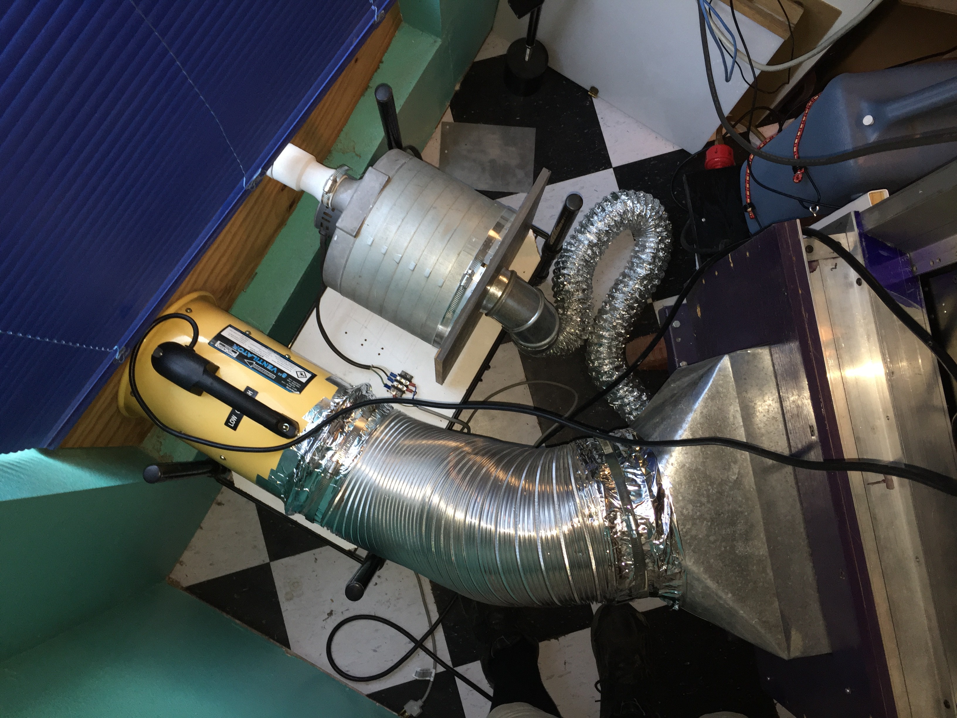
![]()
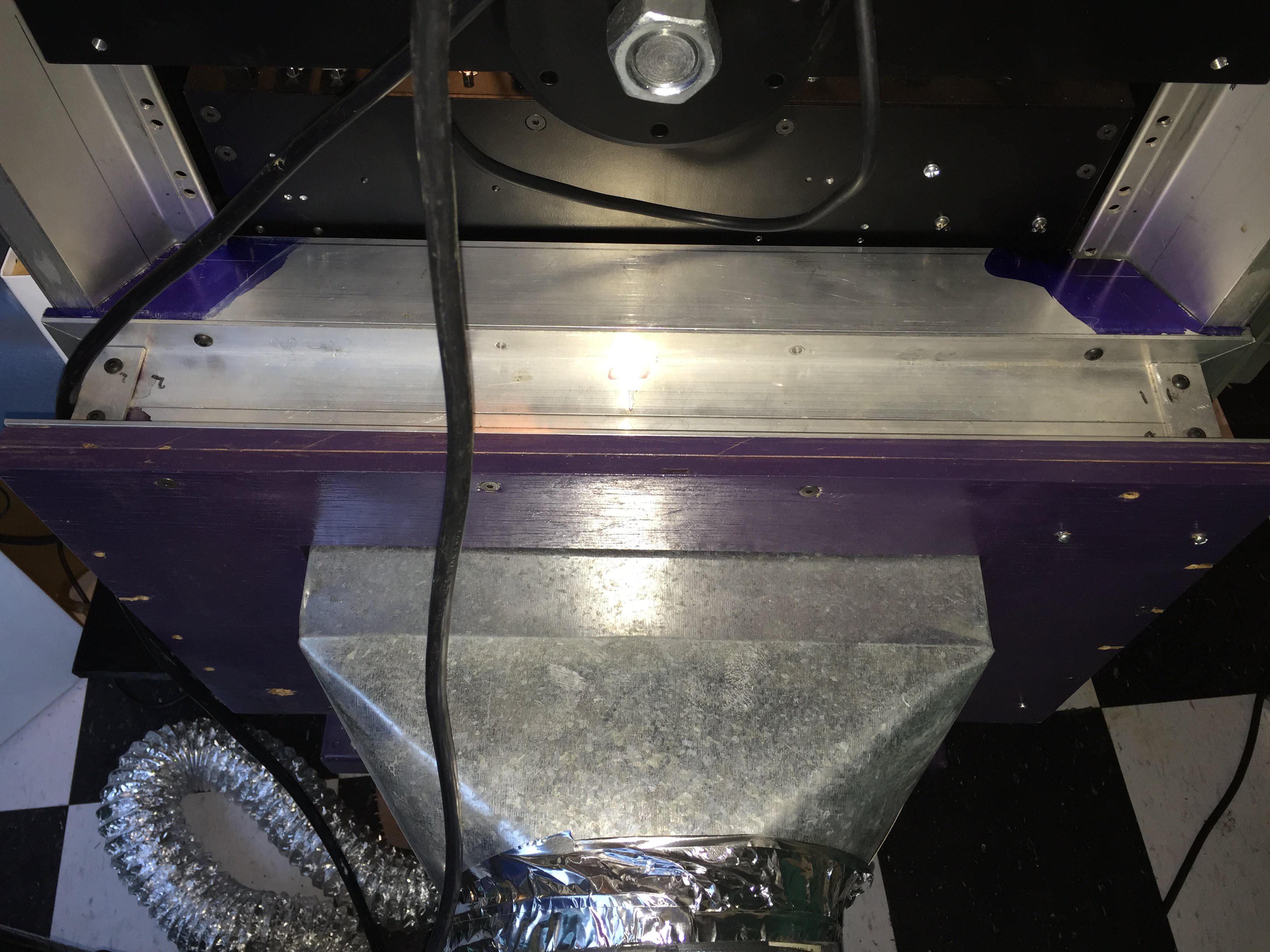
The exhaust plenum took a huge effort. Someday I'll have to powder coat it black.
![]()
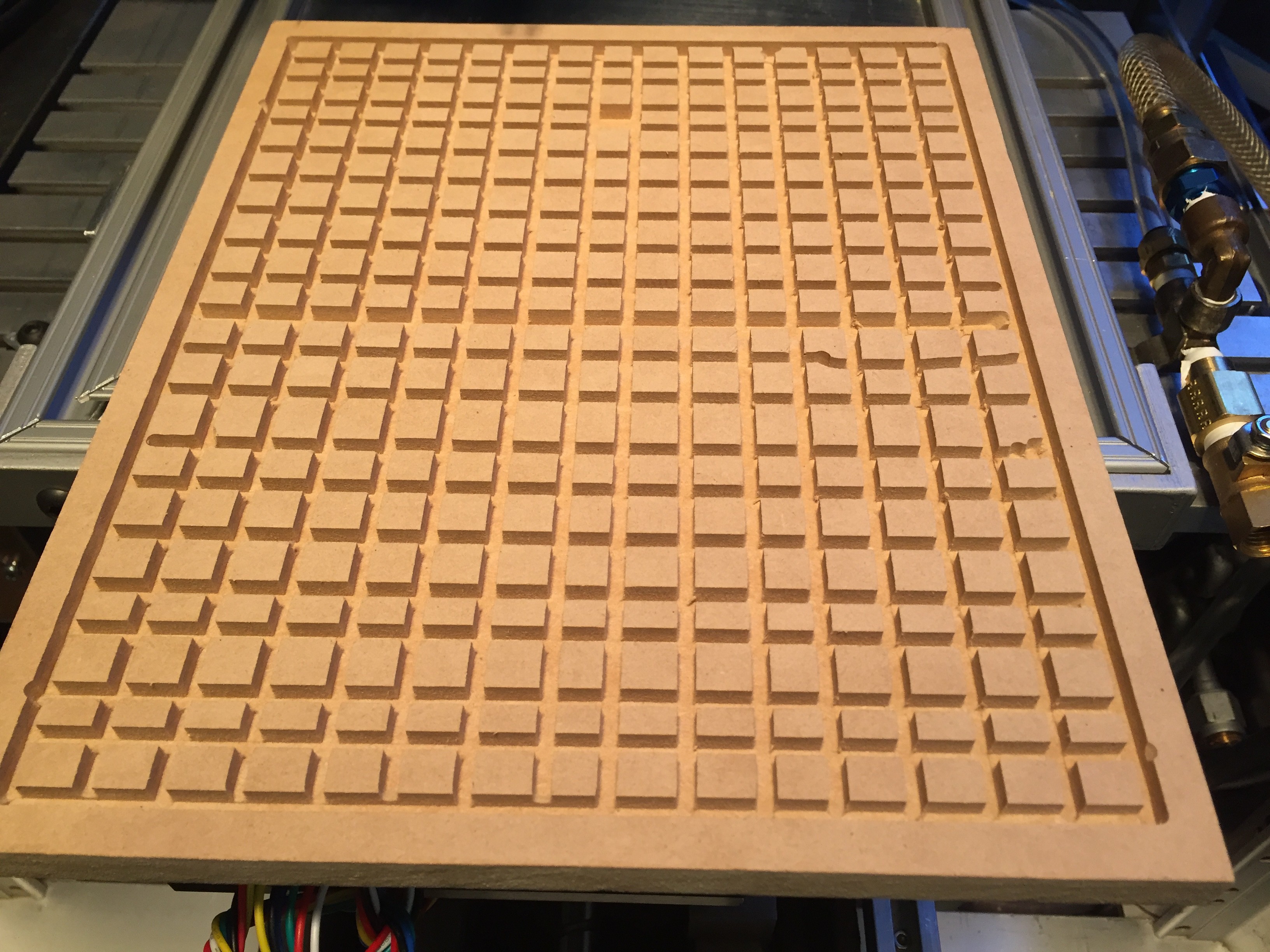
Typically, most cutting is done on a replaceable hexagon grating with sufficient depth that the beam has diverged from it's focus when it reaches the bottom of the cutting chamber. In this system the workpiece is rigidly mounted to the cutting table, so air must be drawn across, rather than down.
![]()
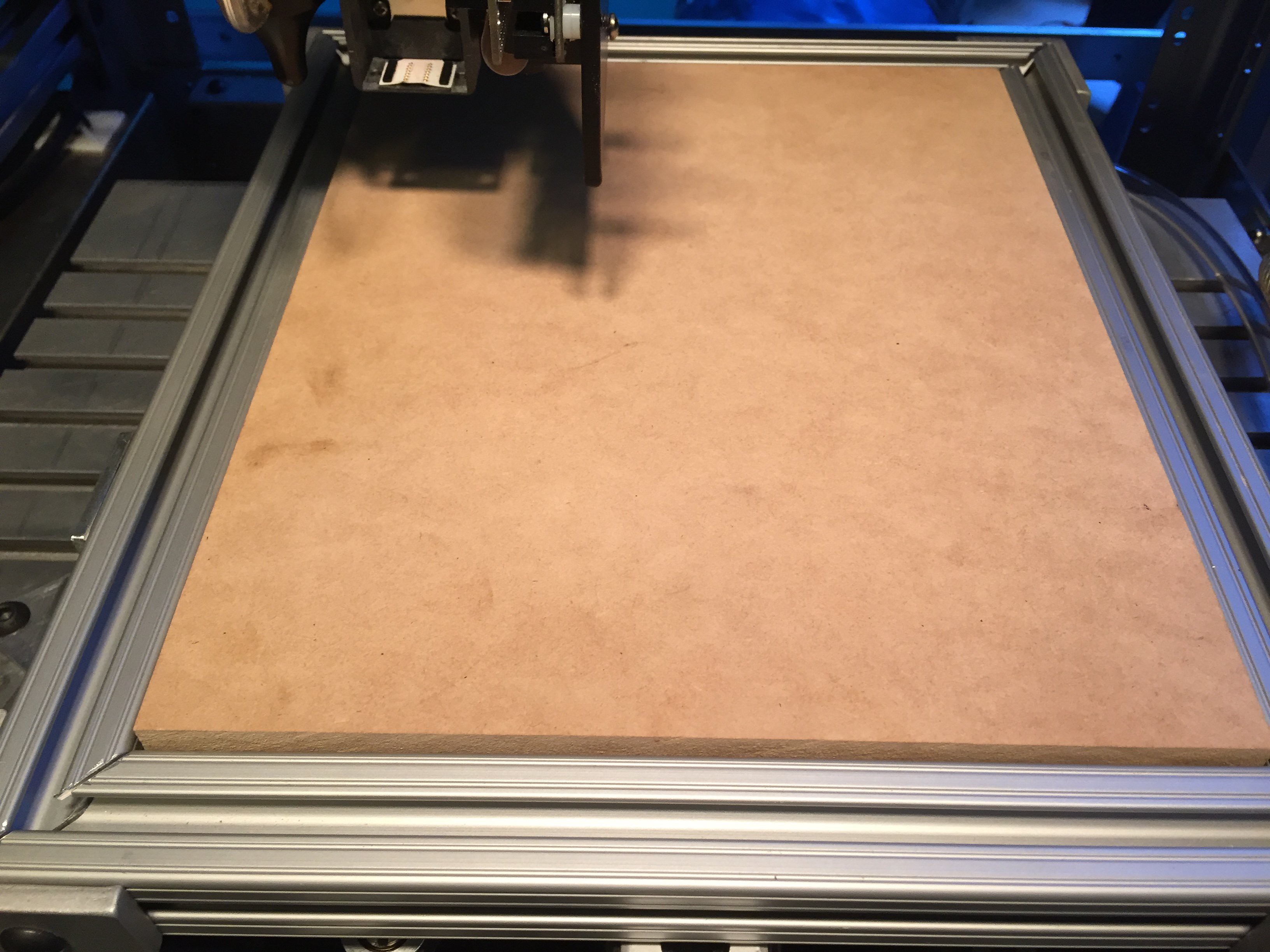
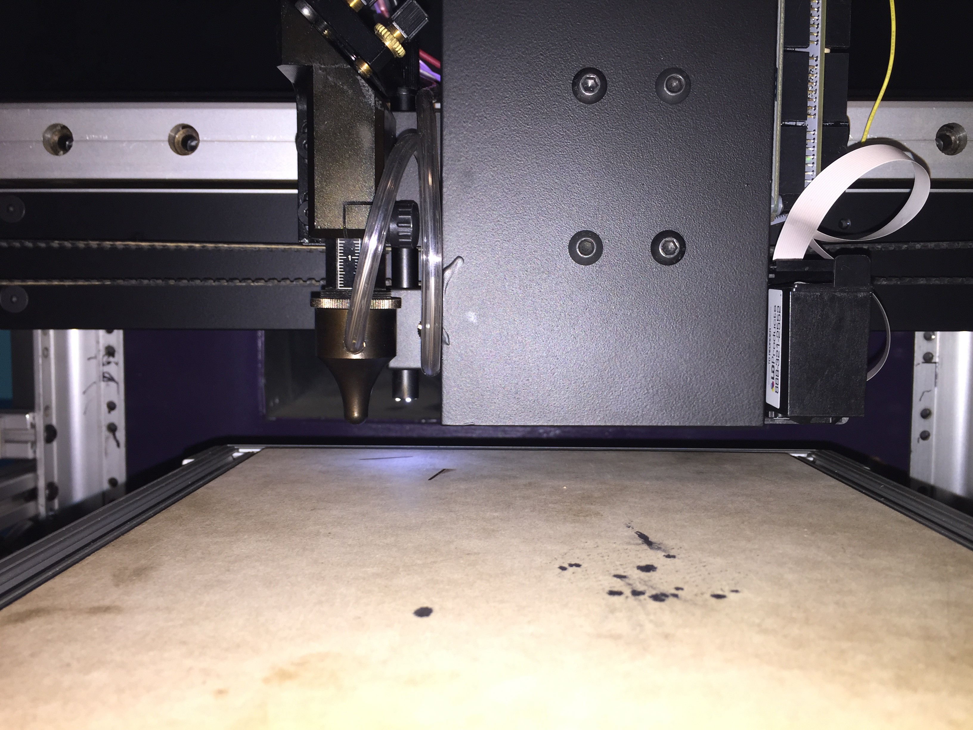
The giant gaping maw of the exhaust system is just visible above the edge of the vacuum hold down.
![]()
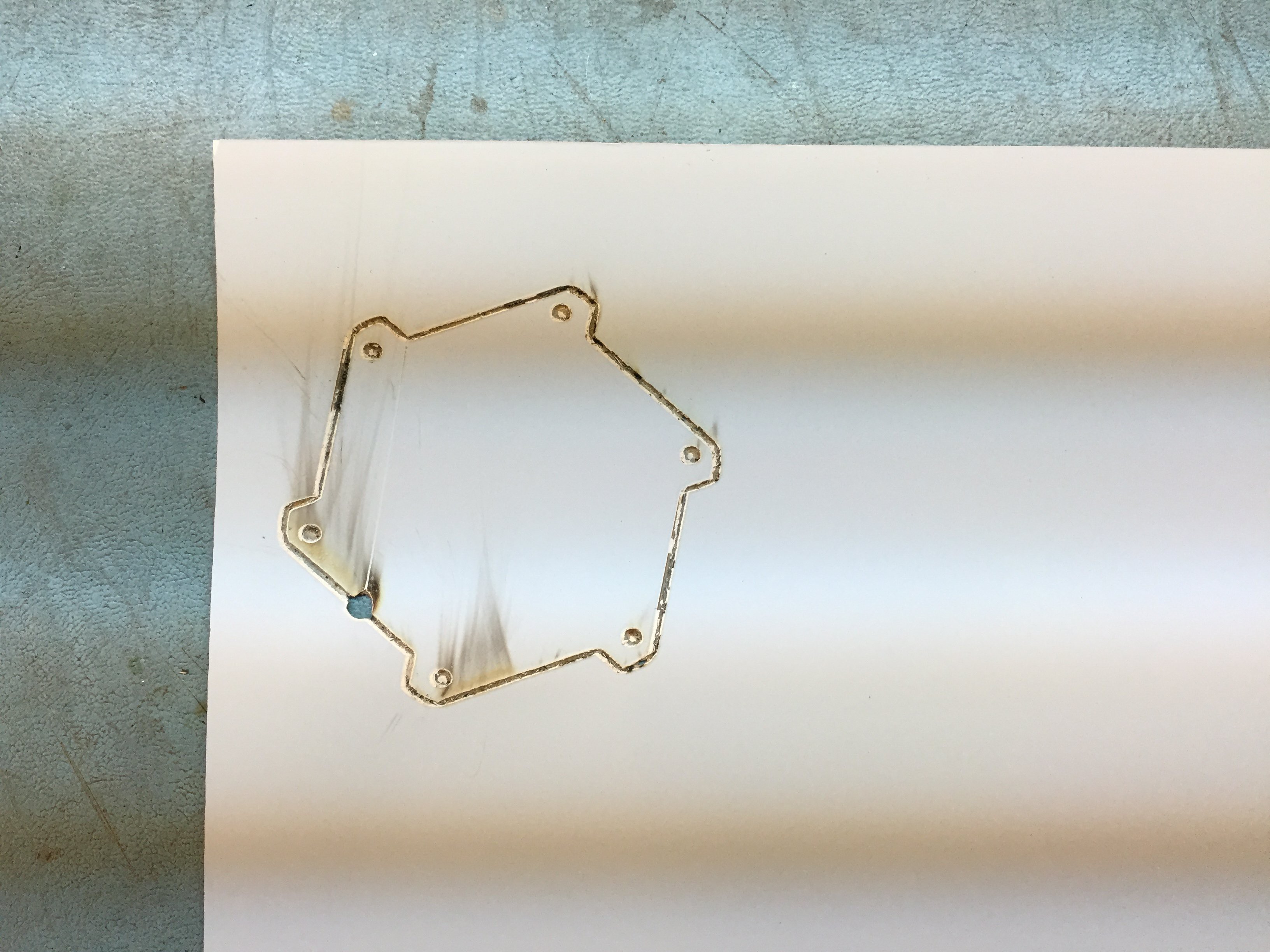
Smoke condensation from the underlying MDF used in the vacuum platen.
![]()
Cleaned up with a bit of IPA.
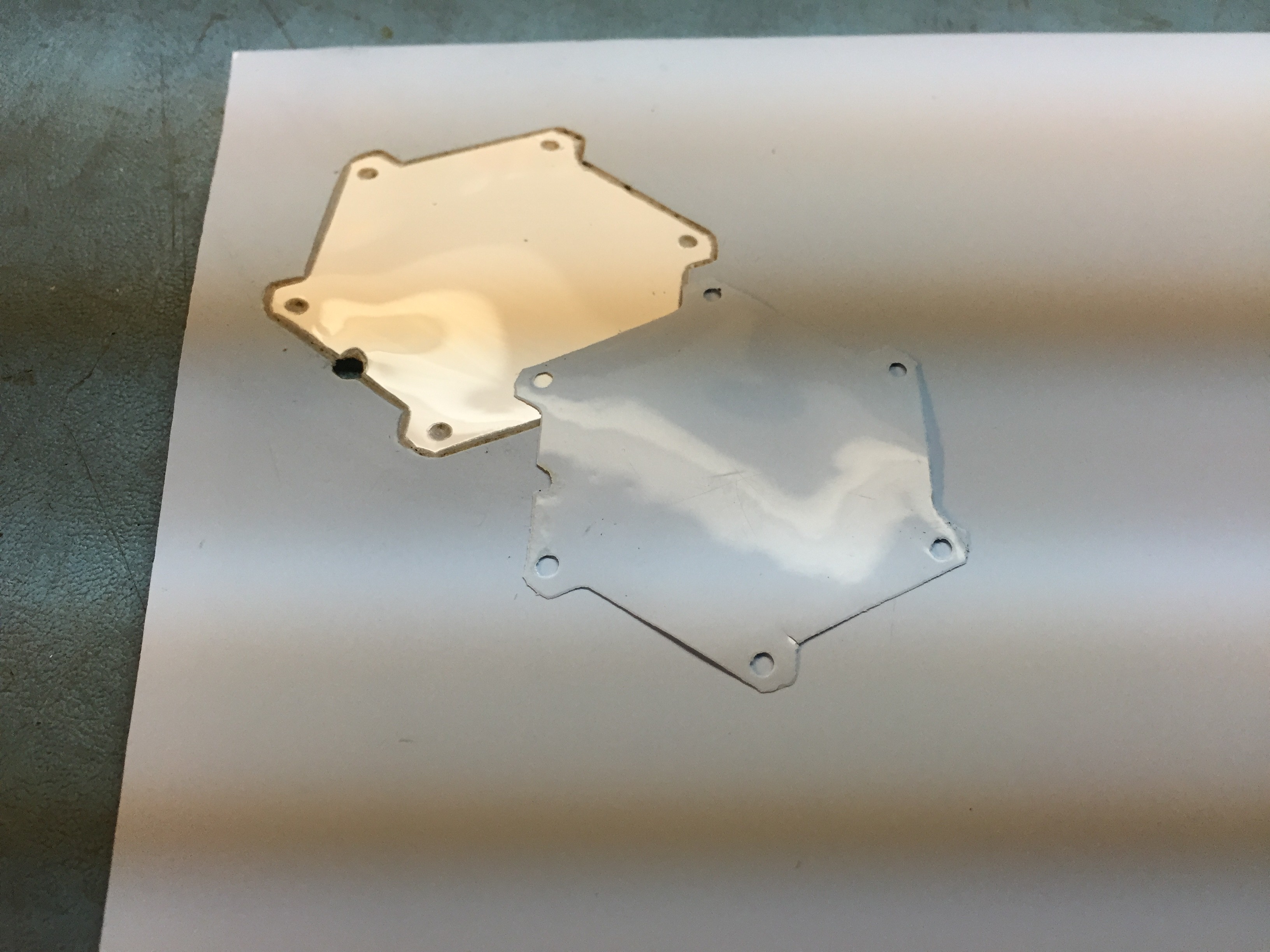
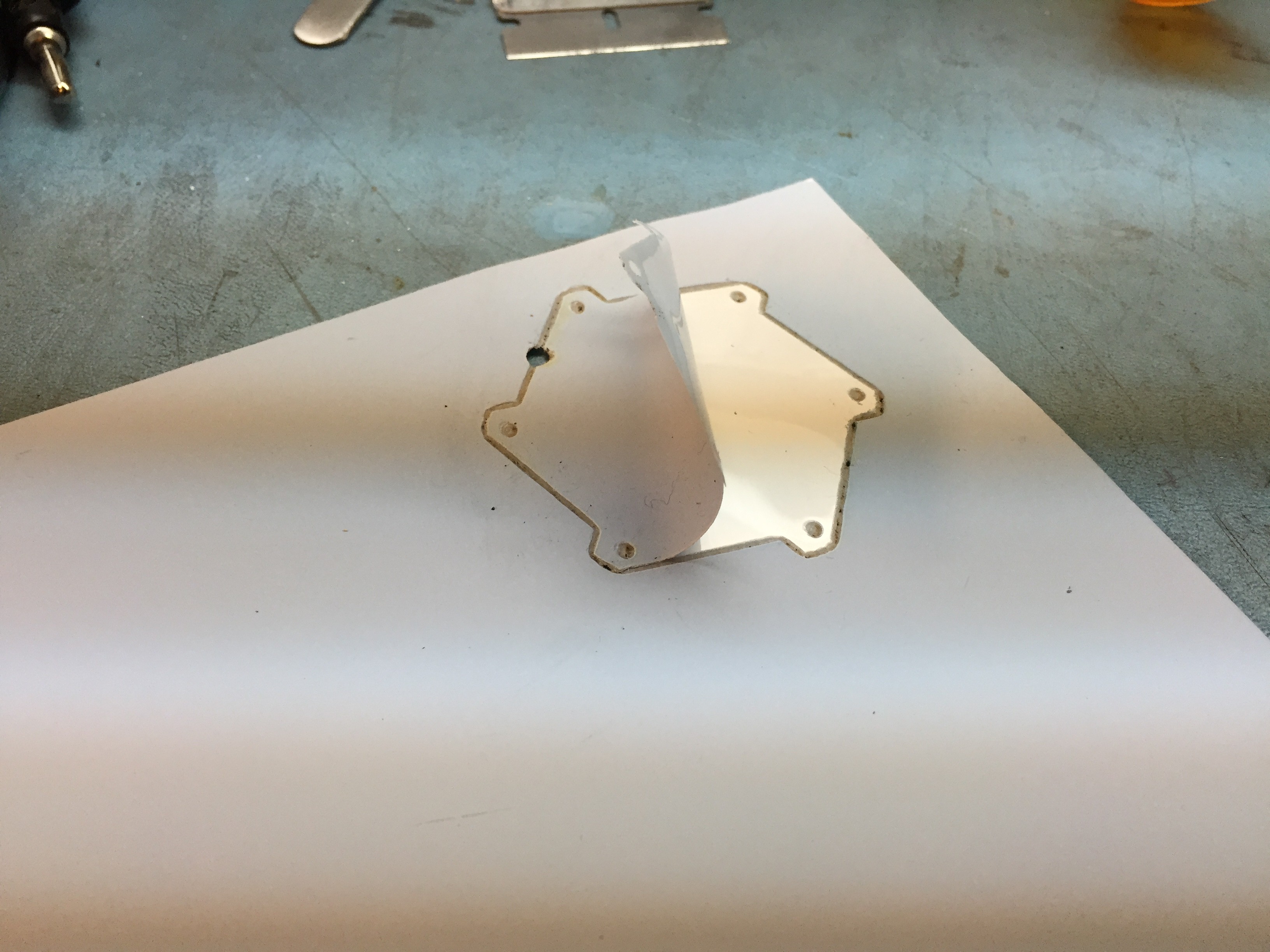
![]() The cover sheet used to support the ceramic green tape is still intact. Can it be that the power level of the laser was perfect? Doubtful. If the energy was not absorbed, and the MDF beneath it was not cut then it must have been reflected back. Interesting! Do not look into laser with remaining eye!
The cover sheet used to support the ceramic green tape is still intact. Can it be that the power level of the laser was perfect? Doubtful. If the energy was not absorbed, and the MDF beneath it was not cut then it must have been reflected back. Interesting! Do not look into laser with remaining eye!![]()
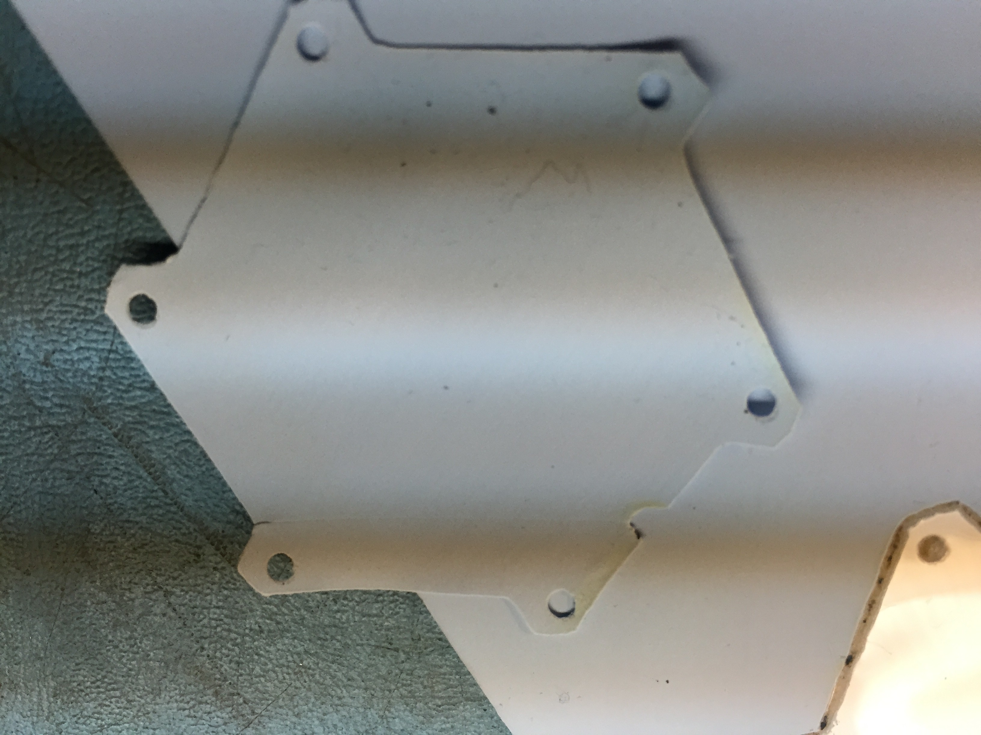
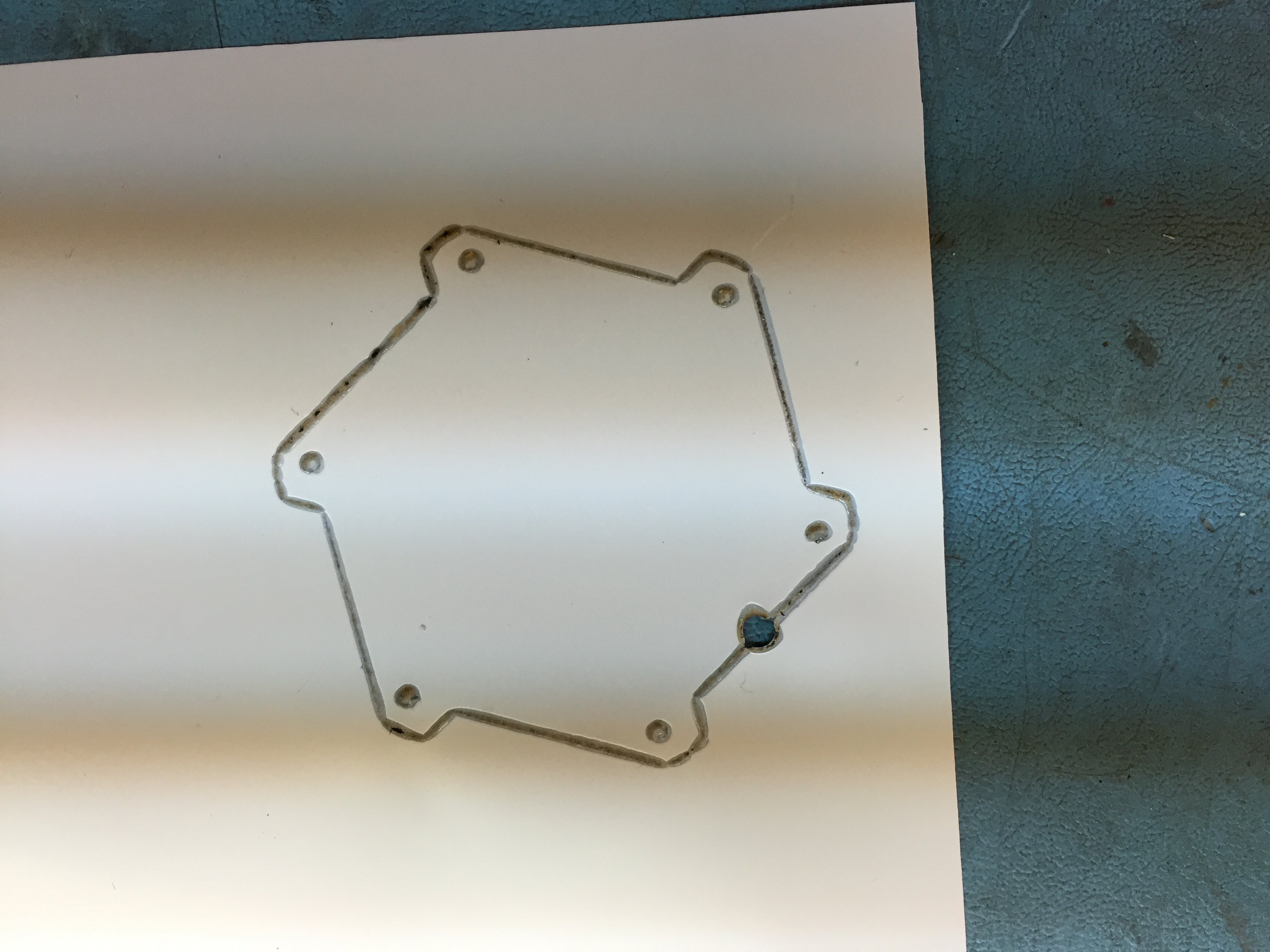
You can see a small tear in the material in the lower left corner. Ignore the divot on the right side. Too many things going on for two hands to coordinate.
![]()
The shiny side of the tape. Tear is very visible. The system was out of focus. A great opportunity for a new series of DOEs (Design of Experiments)
Later this week the MDF will be replaced with a refractory Perlite vacuum plate that will eliminate the smoke and surface contamination.
-
P3 - InkJets aren't so bad after all :)
06/25/2016 at 23:20 • 0 commentsAfter performing a few "Design of Experiments" (DOE) this is what is achievable using a print head that offers 96 DPI, roughly 10mil dots. All it all, this is workable.
Two factors, that will seem obvious are the distance between the print head and the paper and the second is the interval between ink jet pulses.
In the first test the distance was around 1.5 cm and the inter-pulse interval 800uS. In the image below the distance has been reduced to several mm and the inter-pulse period extended to 30 ms. Under closer magnification individual dots are visibly separated which would of course cause an open circuit. Note that as each trace changes direction there appears to be a widening at the apex of the line. Ideally, the ink should be dispensed based upon the true position of the ink head in relationship to the object, rather than assume a constant velocity that simply does not exist. No doubt, correct position based ink dispensing can be readdressed when the system is retrofitted with servos.
The present system is not going to get to 3 mil lines, but it certainly looks as if it might make 10. As a matter of reference, the vias are 30 mils. A standard poker chip would just fit within the board outline.
![]()
This DOE will have to be printed when the substrate is changed from paper to ceramic green tape, and the ink changed to one of the three I have been storing in the refrigerator.
-
P3 - I make a new friend who is a World Authority on LTCC
06/13/2016 at 01:48 • 0 commentsYesterday I met the big Kahuna, in Hawaiian a "wise man or shaman", in LTCC. Twenty minutes down the road. Who would have ever thought? The gods of electrons must be watching after me.
In summary, this project scrapes against the very fabric of technologies that have existed for thousands of years!
For ceramics, history goes back to a fertility totem the Venus of Dolni Vestonice estimated to be 26,000 years old. For laying down the inks upon the ceramic material we go to the Song Dynasty (960 - 1279 AD). These industrial process, that of ceramics and screen printing as they apply to LTCC benefit from tens of thousands of lifetimes of collective effort.
Let's take a seemingly simple example. As is known, if there is more than one layer of circuitry on the substrate the connectivity between layers is accomplished by vias. Tiny, small holes that are generally punched and then filled with a conductive ink. Experience demonstrates that to be successful, the thermal expansion of the ink MUST match that of the substrate. If it is less, the via will separate from the hole wall, and if the thermal expansion of the via is greater it will crack the substrate. The ceramic tape manufactures provide a set of inks for both the vias and the circuit traces. We can be assured that the inks in question are formulated for screen printing and NOT an Ink Jet.
In the case of producing via holes the preferred method is to use a punch and not a laser. This is because a laser may partially sinter the ceramic substrate producing stress risers and the expectation of a substrate failure at some undetermined time in the future. The 3D Fab machine can be fitted with a punch. The use of a laser operating at a wavelength that does not fuse the ceramic metal oxides, primarily Al and Si, but dissociates the organic binders, may be another option. In any case, the system will be fitted with both a punch and a 445nm Blue laser in addition to the systems already existing CO2 laser operating at 10,400 nm.
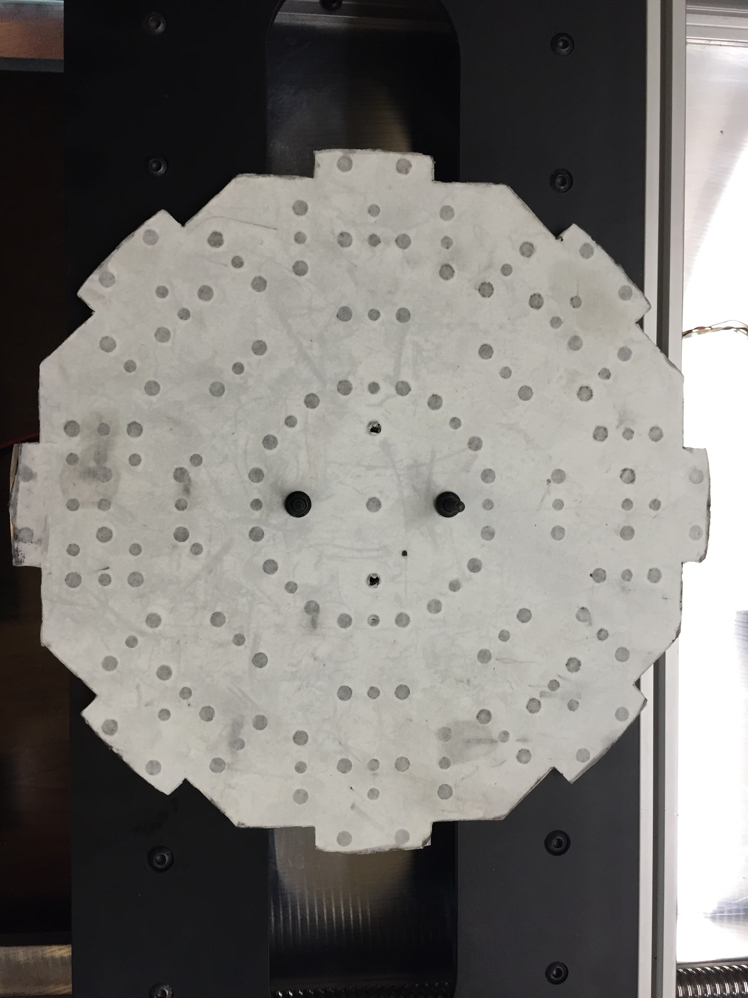
![]()
This is what you get for 36 minutes of Flow Jet water cutting. 151 precision holes. I have no idea how long this would take using conventional machining tools. I know it would take me days. And to do it without any errors. Impossible! The white paper is protecting a very smooth MIC 6 tooling plate. I'm happy to pay the $75 of water jet machine charges it cost to make.
The long bed supports up to 8 tools at any one time. In the 12 o'clock position is a conventional FDM printer head, at 1:30 a piece of 80/20 channel, at 3 o'clock a peristaltic pump that will be part of the ink printing system, and at 9 o'clock a spindle 400 Watt motor. The spindle motor has it's own mounting holes, all the other devices will mount to the 80/20 T slotted channel. There are many hours of machining left to go! So far the list of devices to hang on this fixture are, spindle motor, FDM head, ink head, camera, 445 nm blue laser, vacuum pickup, punch. At each of the positions there is a mount for a precision guide that locks the carousel in position preventing the assembly from rotating as there is about 3 degrees of backlash in the rotary mechanism.
This week the furnace was calibrated. Unfortunately, it has some software issues that need to be ground out.
-
P2 - The vision meets reality
05/30/2016 at 03:13 • 1 comment![]()
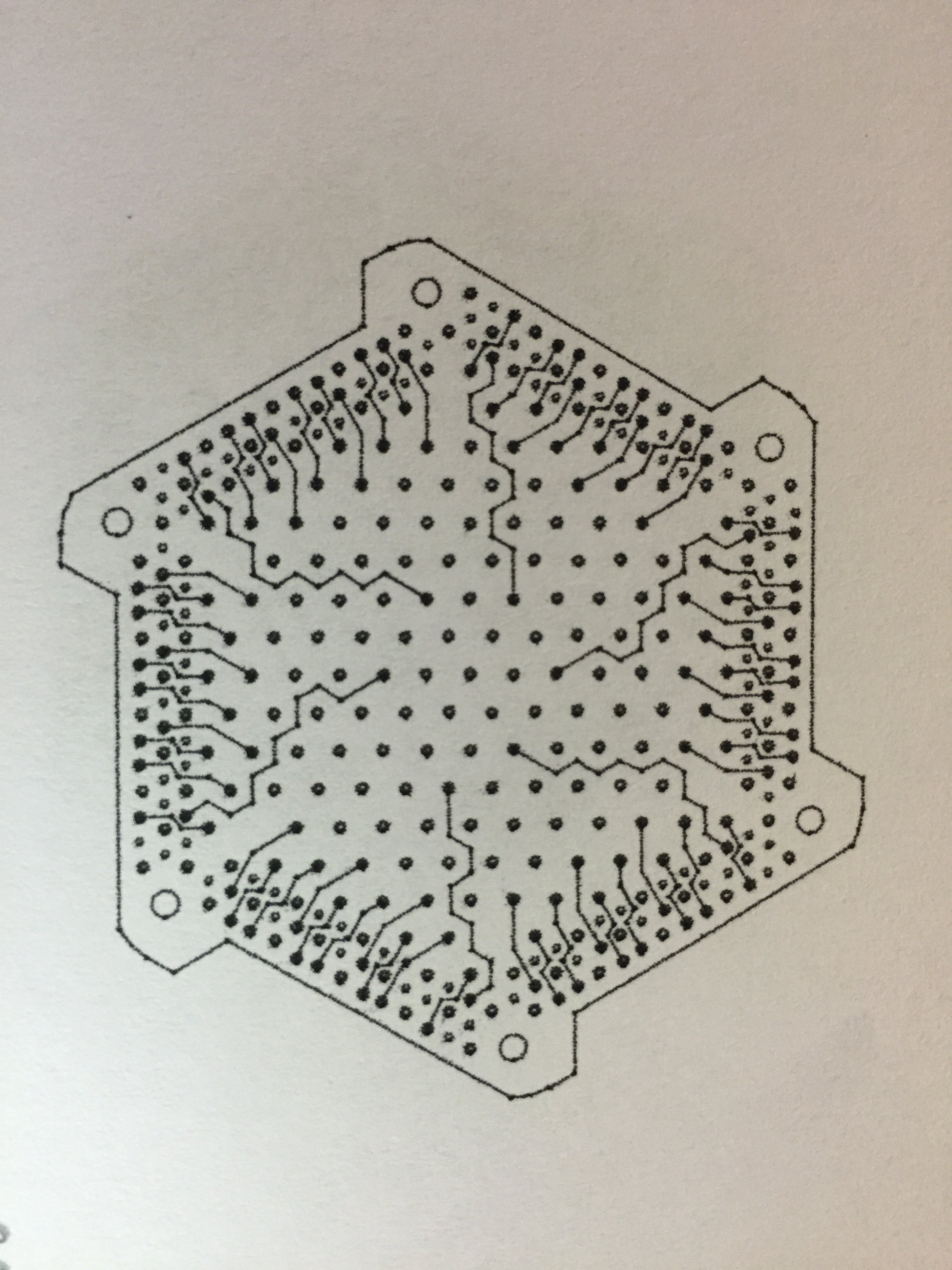
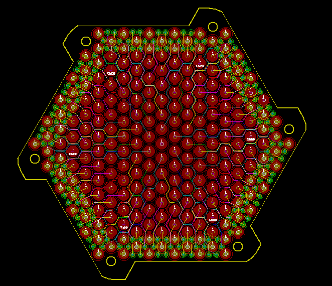
A standard poker chip just fits within the boundaries of this test PCB. Six internal signal layers with 2mm pads on one side and 30 mil pads on the other. Using the absolutely wonderful open source layout tool Kicad, it took three days to layout. 26 mil annular ring with 16 mil drill. Traces are 9.8 mils wide. By any definition, this is pushing up against present day limits.
One thing that's going to take some time to wrap my head around is that the layout rules of LTCC are far, far, friendlier than conventional FR4 PCB circuitry.
There is no cost burden for buried and blind vias! So, all the zigs and zags are unnecessary. If that hole is not on your routing layer, go right over it! Weird!
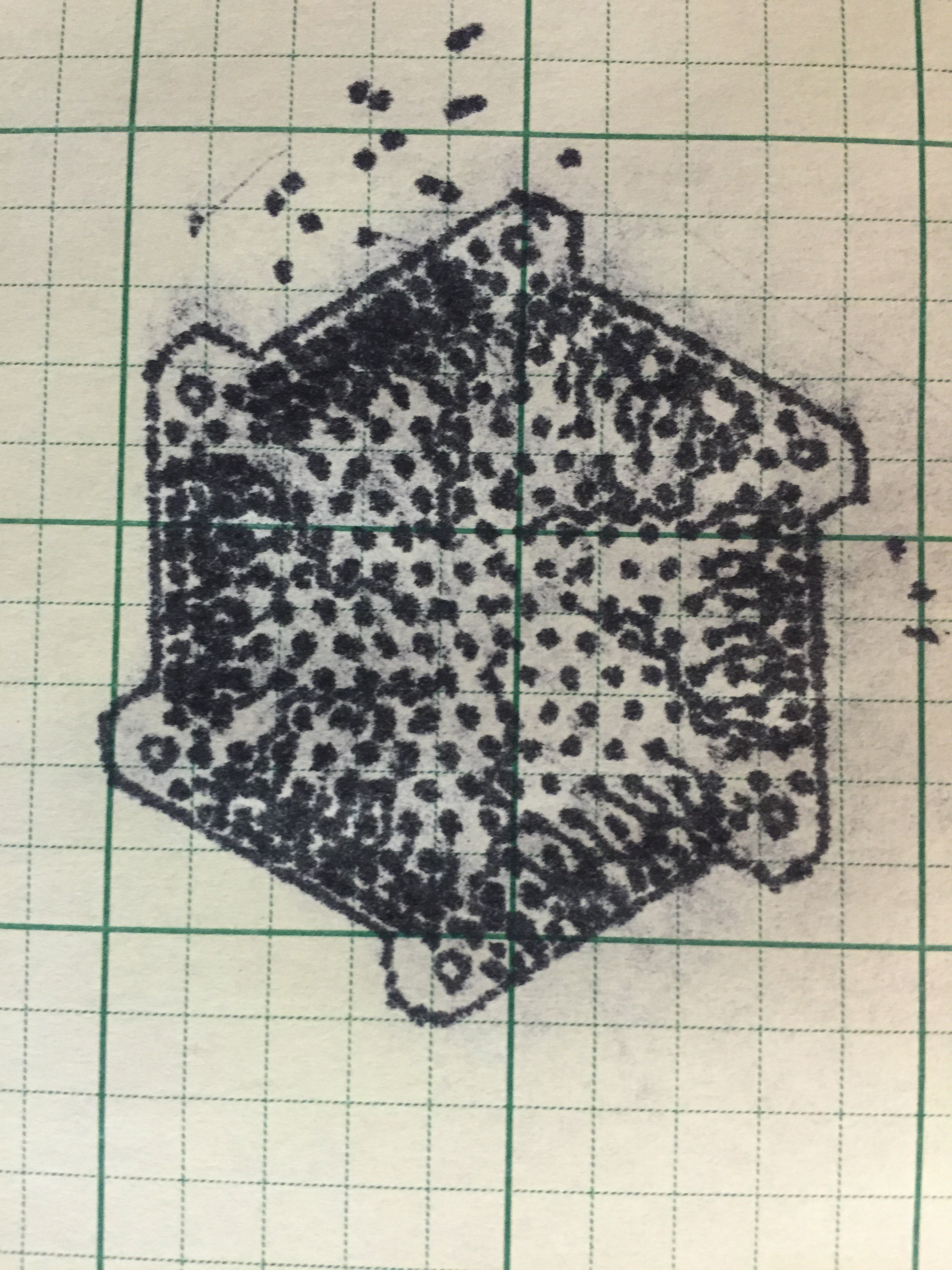
Here's the reality for a single layer, in this case the first inner layer L1.
![]()
Disappointing resolution at best. Keep in mind that the best this thermal print head can do is 96 DPI. Technologically the print head used, a HP C6602 is ancient. There is a cloud as well caused by adjacent channels firing. The exact mechanism may be grounding or just the limits of the technology for this era of Ink Jet.
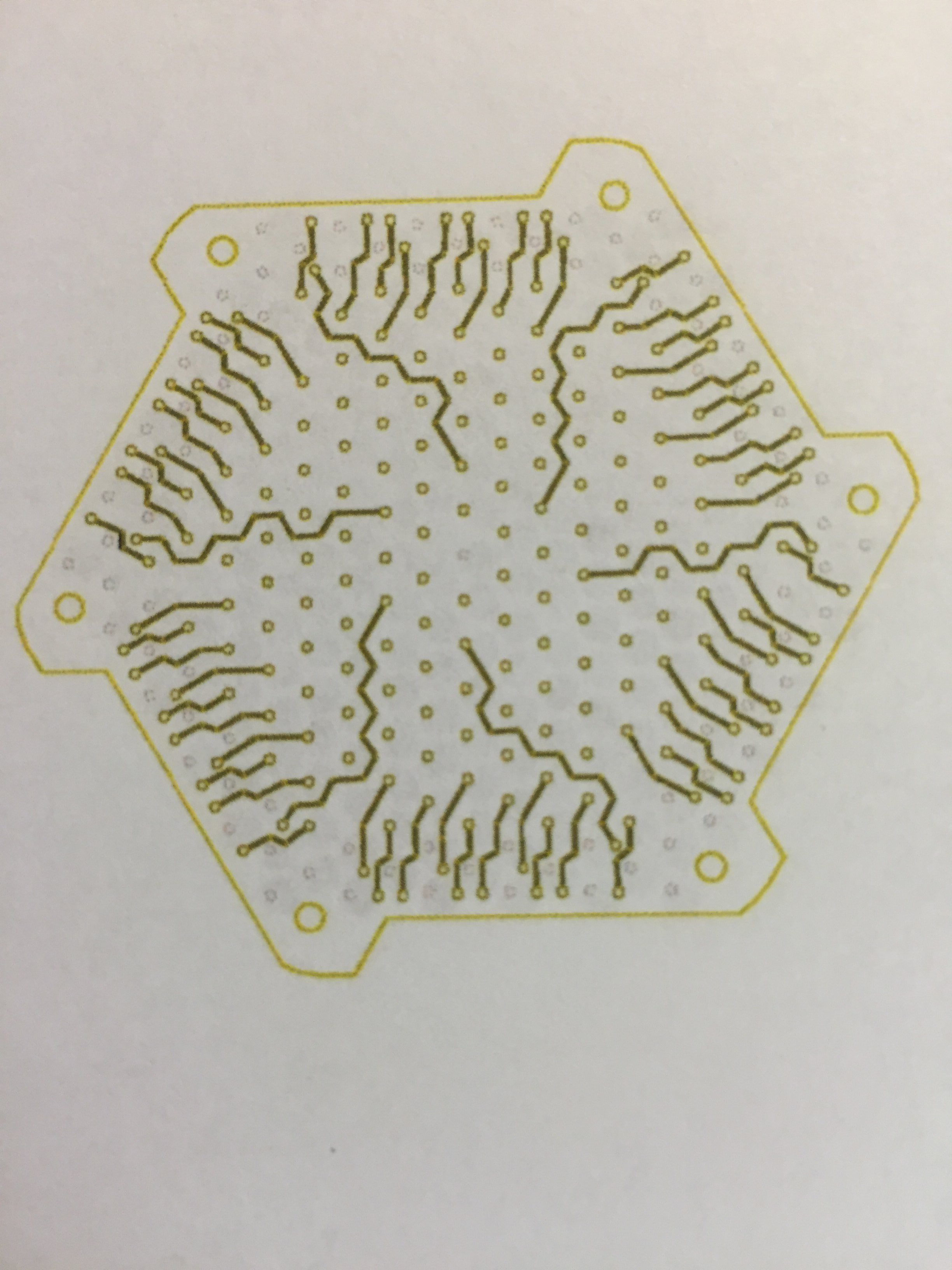
This is what I was hoping to see.
![]()
So, that's 96 x 96 DPI vs. 5760 x 1440 DPI a factor of 900, almost 3 orders of magnitude difference. In this case the printer was an Epson C88. Impressive performance for a printer that goes for < $100.
Incidentally, the C88 uses servos for the page traverse.
So, what does this all mean?
1. It appears that the low performance head will be adequate for printing electrodes on a ceramic substrate. The present test board is well beyond reach.
2. It will be necessary to use higher performance print heads, AKA piezo along with servo motors instead of steppers to reach the desired quality.
3. It should come as know surprise that the software that is available does not match up well to the present hardware.
To use the present CNC system, or any CNC system for that matter one uses G-Code. Most maker related PCB software utilizes PCB milling as the operant technology and are subtractive in nature. LTCC is additive. The artwork for Kicad was exported as SVG images and processed with InkScape and the InkScape extension GCodeTools. However to make an 8-layer board it is necessary to generate no less than 16 seperate files. Eight (8) to drive the laser for the drill files and eight (8) printer files. To have any hope of having a usable system it will be necessary to have the software parse gerbers and partition each of the layers into strictly placed regions so that only one alignment between the laser and printer will be necessary. FlatCAM may be a suitable starting point for some hacking. It's going to take some very serious coding to make this work.
Better to fail often. One cannot reach the goal without constantly correcting the course.
Closing on an upbeat note.
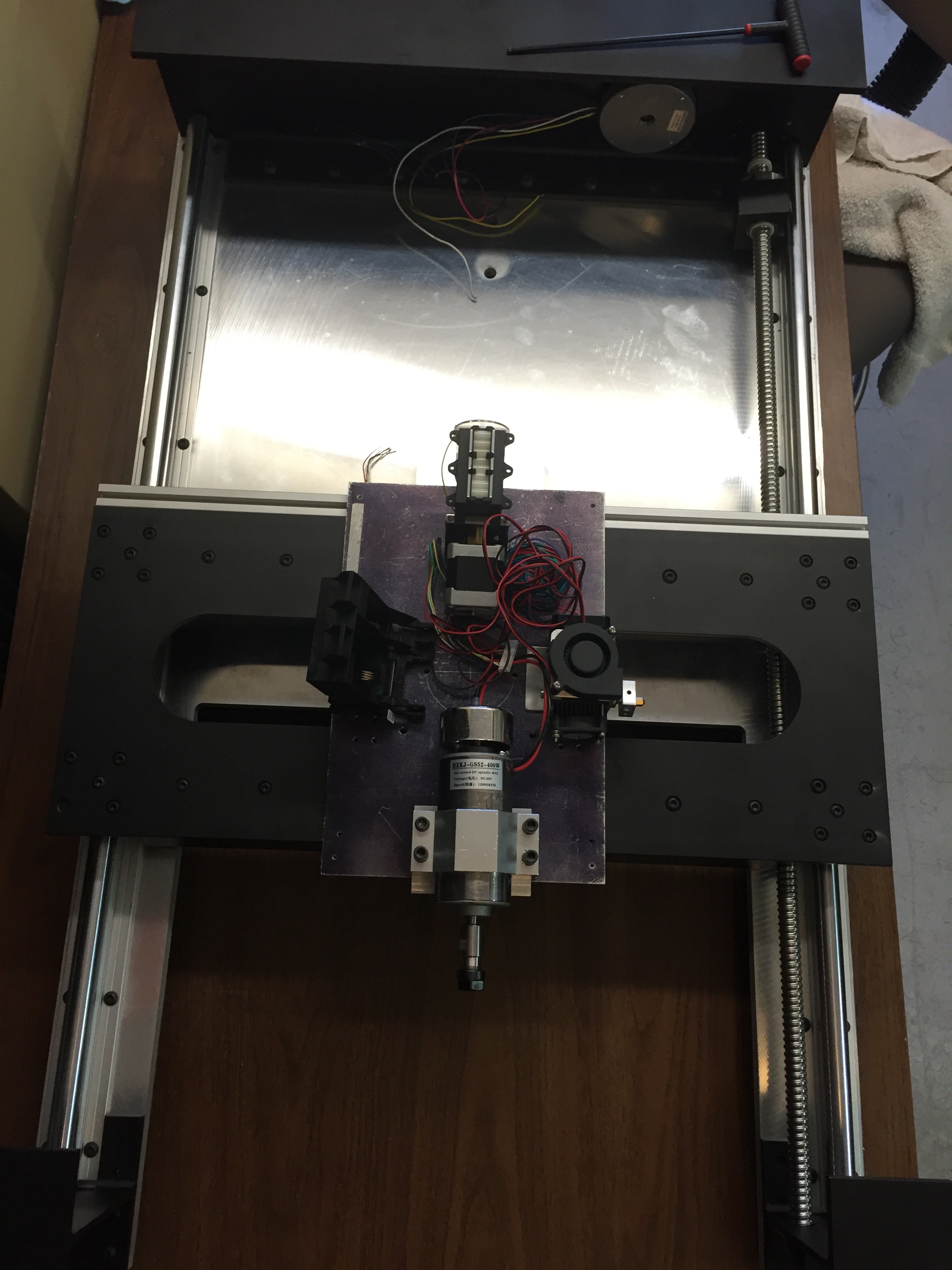
This is what the long bed really looks like.
![]()
The rotary table will more than likely have 8 positions. Shown are a 400 watt, 30K RPM spindle motor, conventional FDM print head, peristaltic printer head for depositing colloidal suspensions, and a piezo print head. To be added are a camera, vacuum pickup, touch probe, and TPD. In any case, 7 of the 8 positions will utilize 80/20 mounts so they are universal.
Might as well start here for the X traverse servo.
So, all in all, it looks like for this second round I've managed to dig up a huge can of worms. Not bad for 6 weeks of effort and lots of 16 hour days!
-
P2 - Revisions to Tool Head
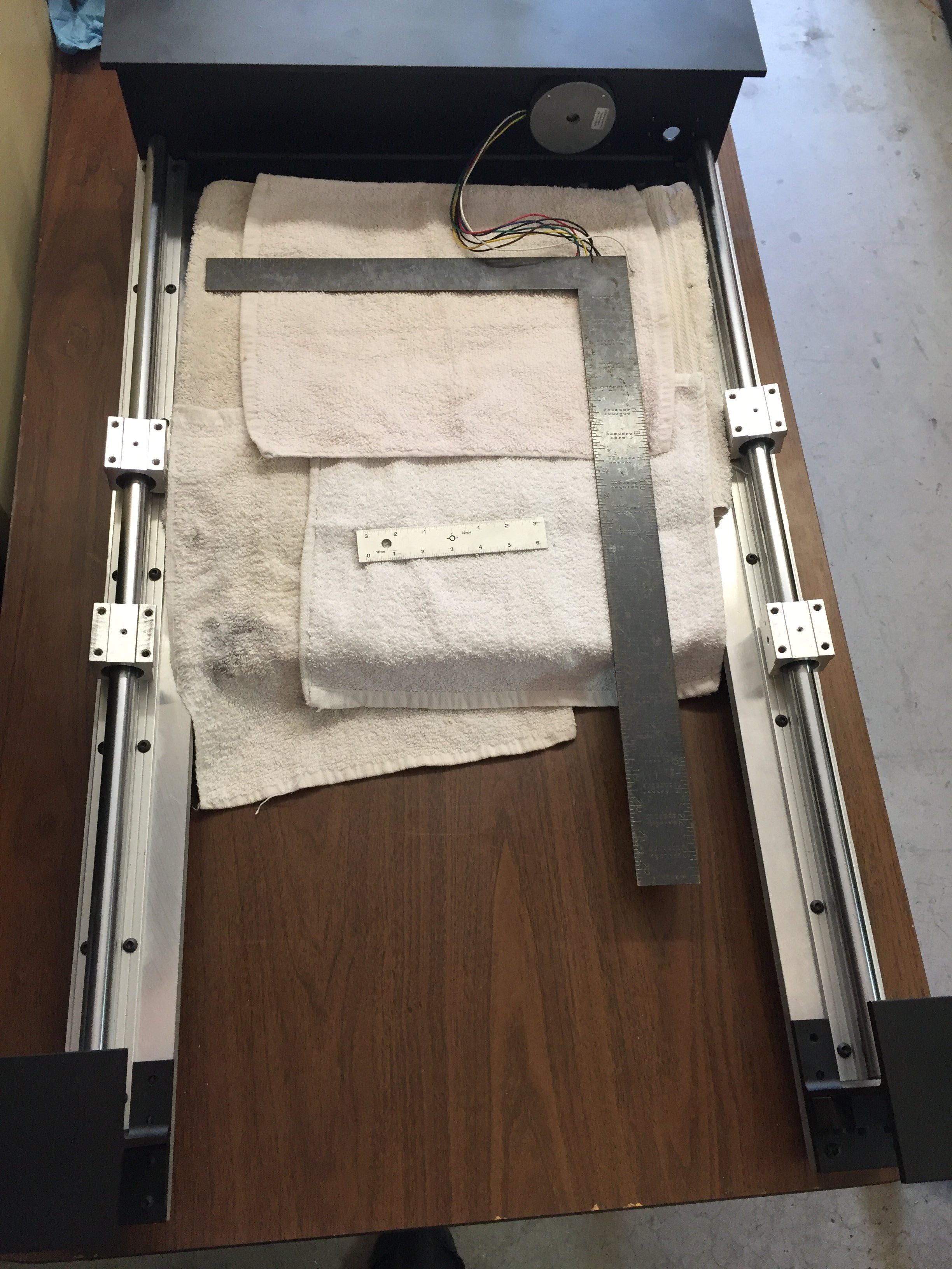
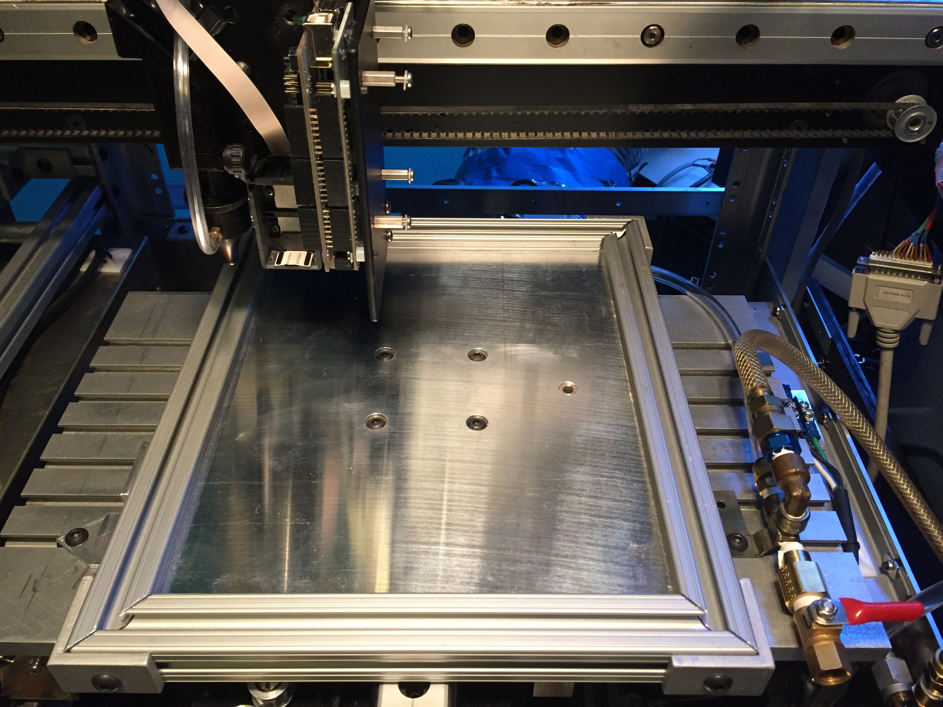
05/26/2016 at 19:15 • 0 commentsThe original tool head was encroaching on the working space of the Long Bed below.
![]()
There is one problem with Powder Coating. Once you start, you want to powder coat everything! It's really important to keep towels over any flat surface. It would be unfortunate to have it marred by a careless twitch of a tool. The long bed is 1/2" MIC 6 aluminum plate and is very flat and smooth. The profile and the holes were all machined on a Flow Waterjet cutter. You can see the water jet in the background of my profile picture. Love that machine!!!
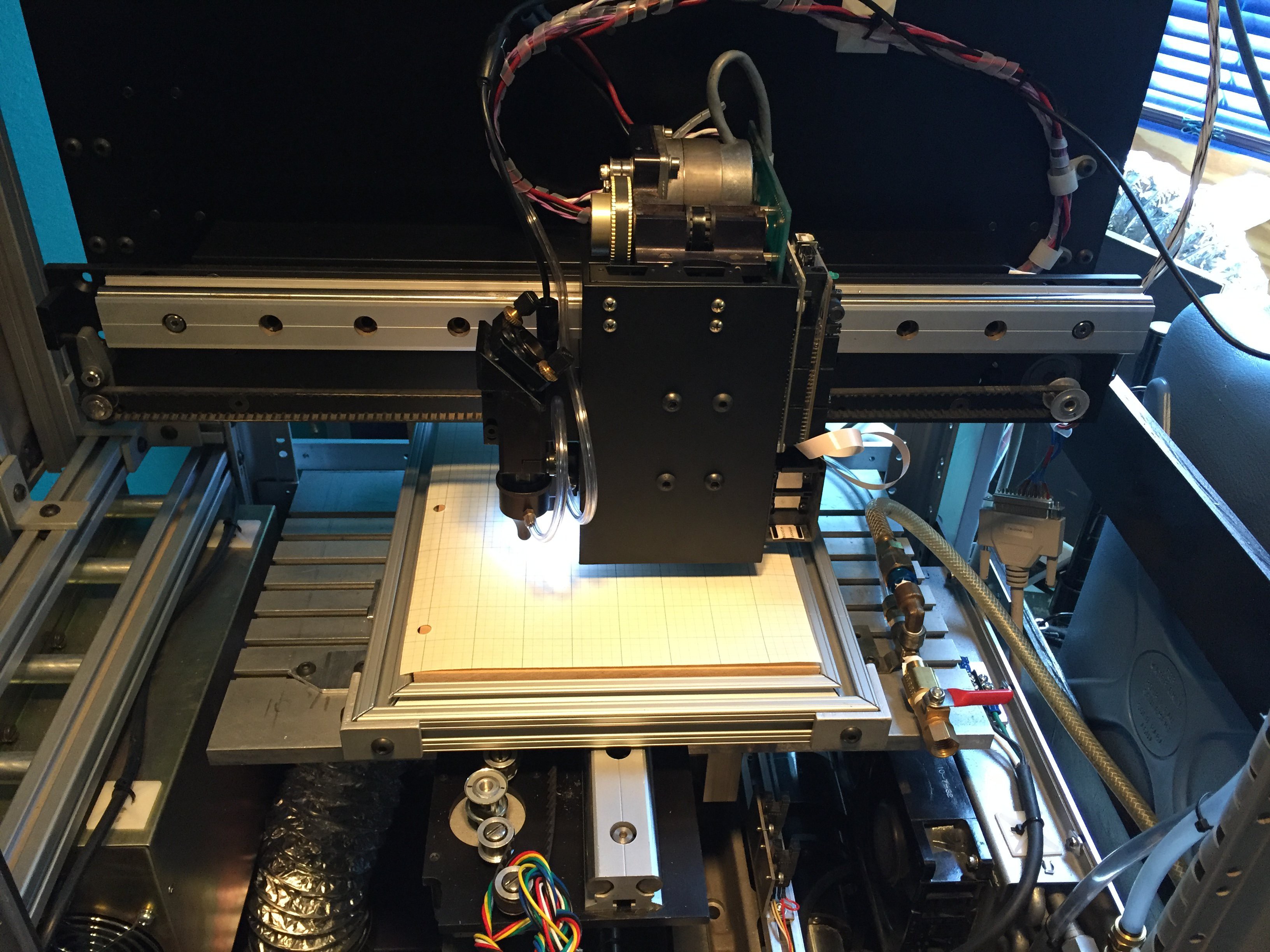
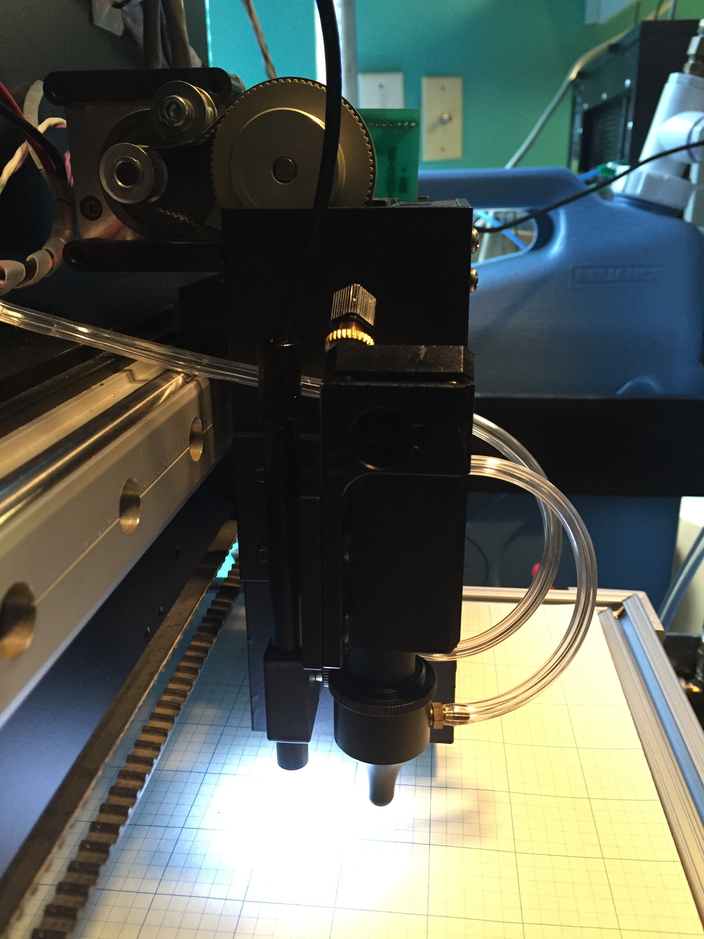
This is the new tool head assembly. It recovers about 4" of Y axis work space. The InkJet has been moved as far away as possible from the camera optics.![]()
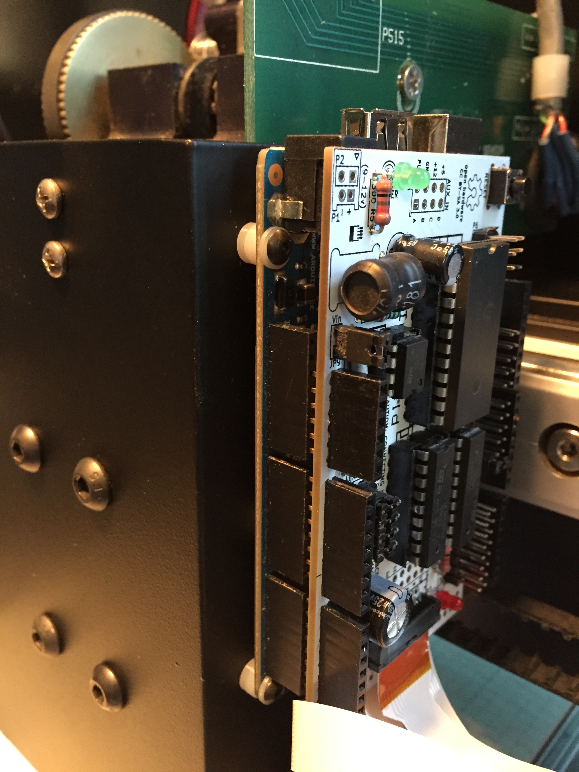
Shown is an InkShield InkJet controller mounted to an ATMega 2560. The Arduino is a great asset. So very easy to use. Inexpensive.![]()
![]()
It really is astounding what less than $30 dollars will buy. In this case a very nice USB microscope.
![]()
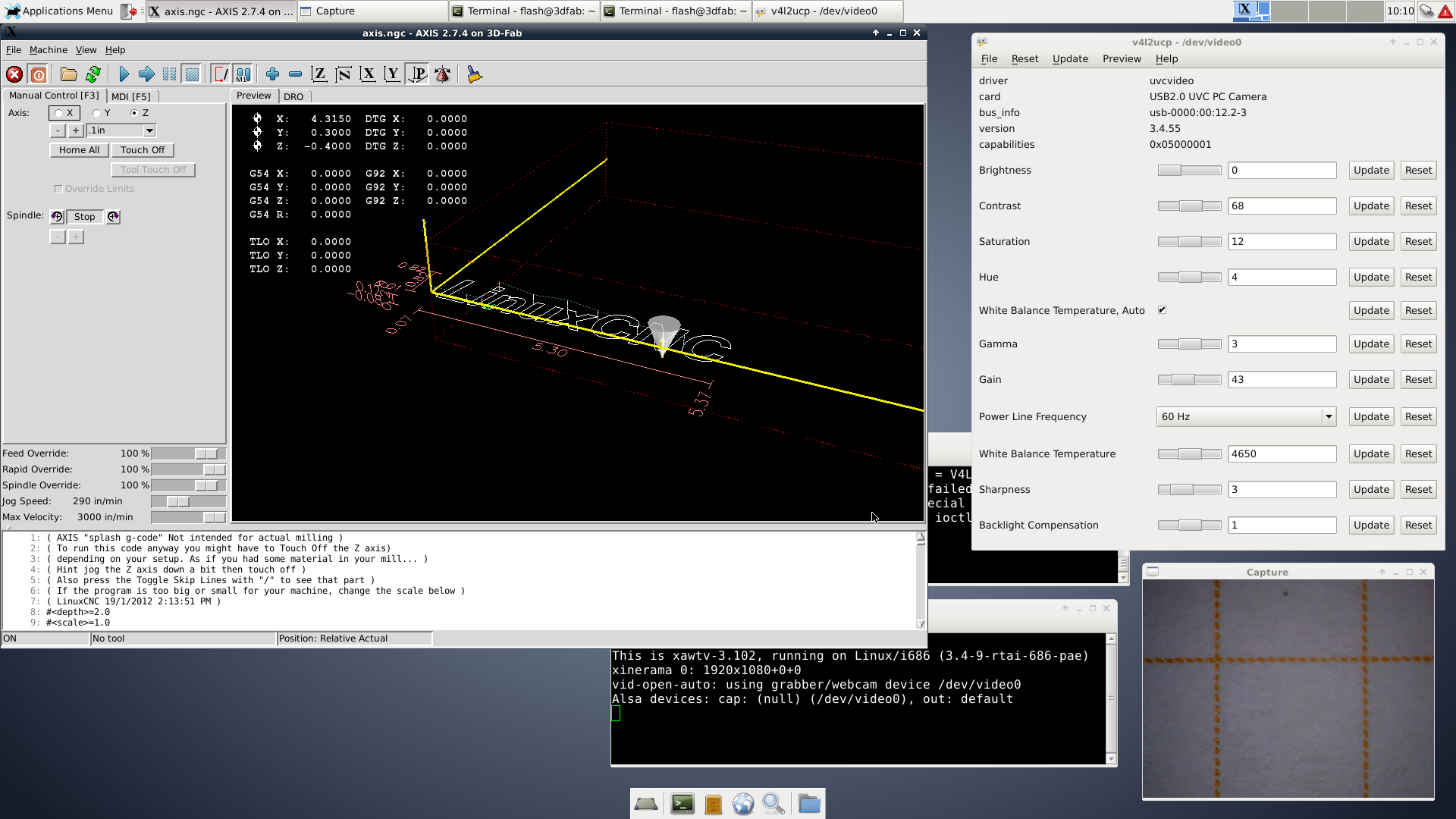
In the lower right corner is what the microscope sees. If it were moved closer and refocused, one (1) orange dash would fill the screen.
In the upper left corner is the linuxcnc user interface. Note the numerical readout indicating the tool head location. To align the system the camera is used to measure the distance between the spots produced by the laser and inkjet. This then provides an offset from the home positions of the tool head that may then be entered into the G-Code programs do the heavy lifting of actually cutting and printing of the LTCC ceramic tape.
-
P2 - Theory of the Bioelectrode
05/17/2016 at 08:29 • 0 commentsIn 1948 Arne Tiselius received the Nobel Prize in Chemistry for "for his research on electrophoresis and adsorption analysis, especially for his discoveries concerning the complex nature of the serum proteins".
Electrophoresis is a method for the separation of macromolecules (DNA, RNA and proteins) and their fragments, based on there size and charge. * Wikipedia
Practically, electrophoresis is the process of running a current, typically at a high voltage, sometimes exceeding several thousands of volts, typically through a gel.
In should come as no surprise that electrophoresis is a very big deal. Without it we would not have sequenced the human genome, or any other genome for that matter. It may, in fact, be the primary enabling technology for all of molecular biology.
There are only a few metals that are suitable for electrodes. Platinum, Palladium, Silver, Mercury, Carbon, and Gold.
Ordinarily, one uses a platinum wire for the electrodes. To use any other material than those listed, say copper, serves only to illustrate profound ignorance.
Platinum is typically used where high currents and durability are needed, Carbon is bio compatible but noisy, Silver is electrically quiet and generally preferred. Mercury makes for very nice electrodes but for obvious reasons and the hysteria associated with it's use only used where very high performance justifies it's downside. Gold works, but other than it's chemical inertness has nothing to recommend it's use.
For signals as might be associated with the measurement of EKG, EEG etc. Silver is the material of choice, actually it's a bit more severe than that. It's the only usable material.
So, what does this mean in practical terms. The electrodes will always be attached via a wire. If you take a look at EEG systems all over the world, thousands of them. People sitting in chairs, with a cap on there head studded with electrodes with wires running off to a box generally out of the frame. Same way for EKG systems, millions of them, electrodes stuck on the chest with wires leading off to a box.
For someone who is to benefit from the use of a prosthetic device the hard reality is that the device get soiled and dirty. It will need to be cleaned. People need to put on their prosthetic device like they put on their socks! When the device get dirty, they need to throw it into the wash with their jeans, T-shirts, and dirty rags from washing the car.
The reality is that is is a long, long, ... long way from sitting in a chair playing a video game using your EEG to sitting in a wheel chair as an ALS patient and navigating across a busy intersection on your way to work. In one case, perhaps you''ll make the evening news showing off, once again, just like it's been done many times before of using the EEG for some kind of "thought controlled" gizmo, to actually helping people go about their lives in a routine fashion that is no more news worthy than today's weather.
It is the paradigm of electrodes connected to boxes with wires that MUST be broken. Totally destroyed! Relegated to the dustbin of history.
Electrodes must be connected to their supporting electronics directly. Electrodes, electronics, connectors, and housing reduced to something the size of a coin "token". And so when you hear your change rattling around in the dryer you'll know that you can either wear it or spend it.
That's why I've gone to the trouble of making PCBs using a ceramic technology. It's the only practical, technologically proven way to connect silver bio electrodes to the electronics in one integral body.
-
P2 - Ink Jet Print Head
05/11/2016 at 17:39 • 2 commentsI can see a light in the tunnel and it's not the sun at the tunnels end. Sounds more like a big engine that's going to suck me from wherever I can hide straight into disaster.
The name on that big engine is Clog.
There are two basic types of Ink Jet printers, thermal and piezo electric. In general, although I don't know that it is universally true, thermal printers are disposable, whereas piezo heads are builtin to the printer. For now this project uses disposable thermal heads for which the various ink manufactures tend to depricate in favor of piezo heads. They won't come out and say "Don't use a thermal print head", it's more like, "we suggest you use piezo heads".
My experience is, Ink Jet printers clog. The bottom line is I'd rather make my own piezo head and clean it as necessary, rather than keeping a stock of print heads handy.
Here's the effort so far.
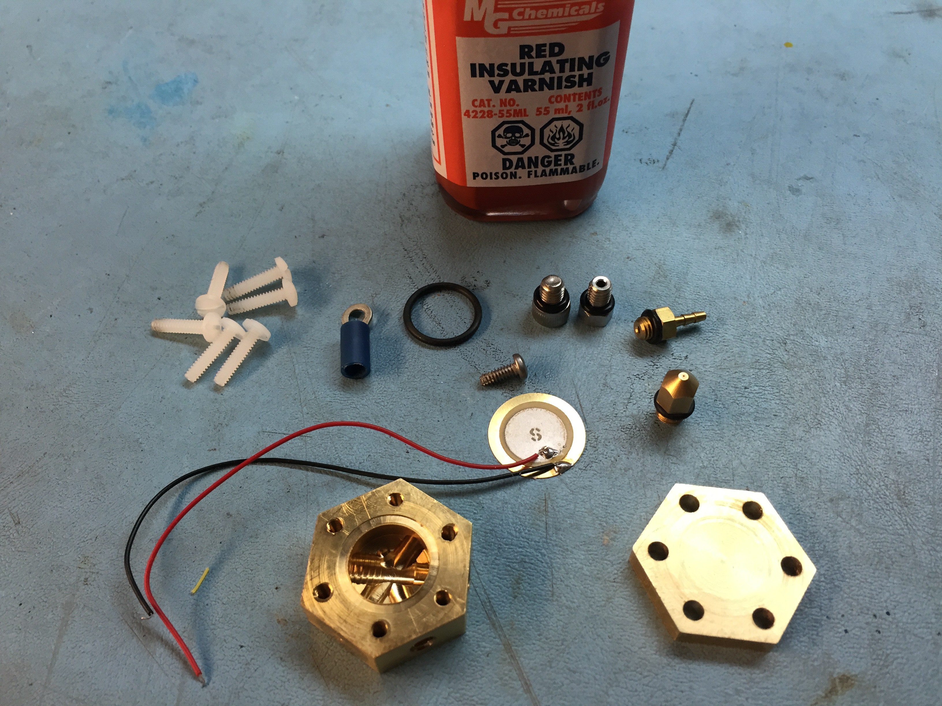
![]()
The black O-ring fits into the grove surrounding the cavity. The black wire on the bimorph is removed with the piezo surface facing the interior. After every is assembled it looks lie this.
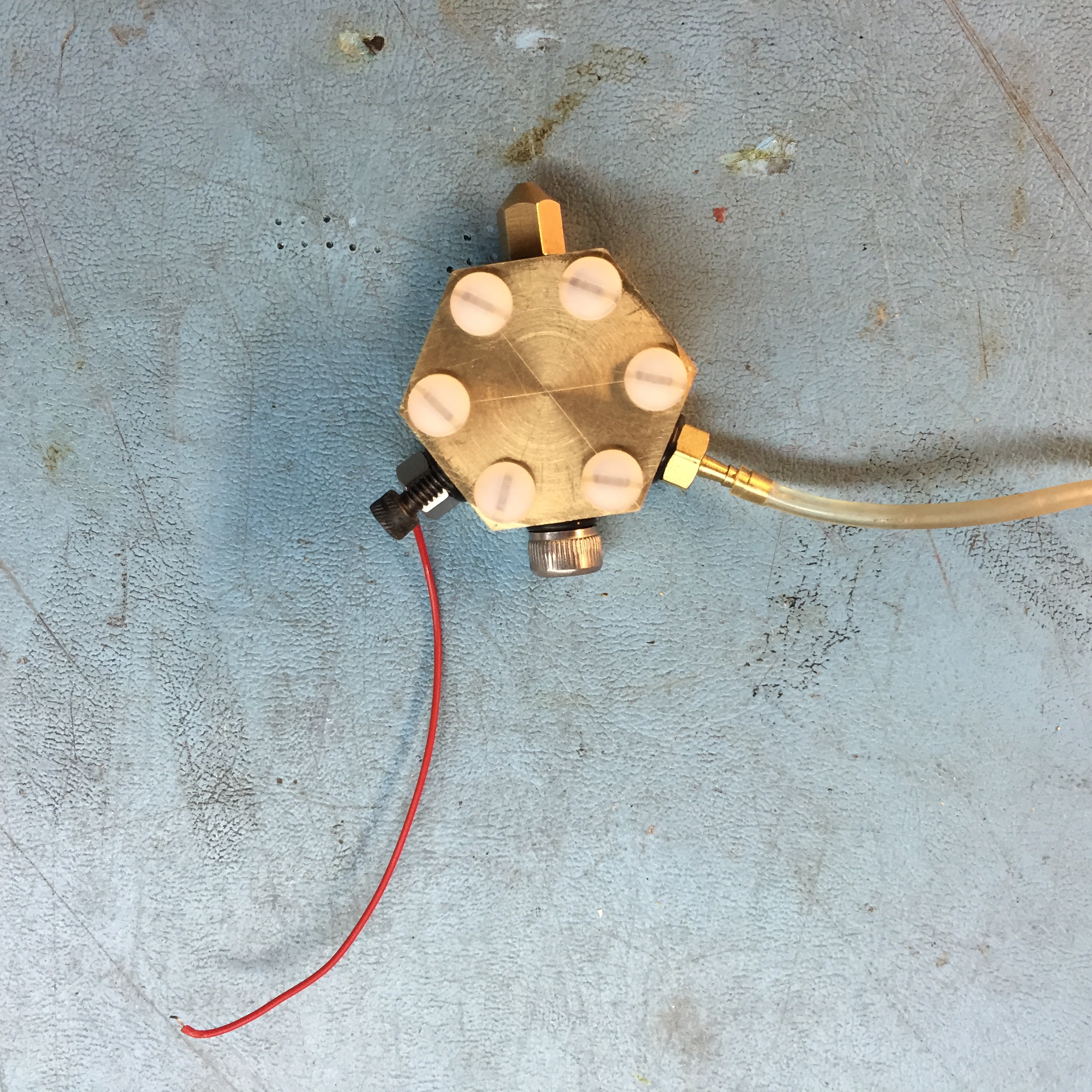
![]()
So far it's a spectacular failure!
It has SO many problems! The volume of the cavity need to be reduced by a factor of 10,000, the jet diameter needs to be reduced from 0.3 mm to 30 micrometers, and I'll need to use a real pulser.
That ol train keeps getting closer. Better get on it. On the up side, this isn't rocket science. It's just the application of first principals.
On the positive side, the physical dimensions of the device are good, form and fit seem OK, the fluid line is about the right size.
-
P2 - Vacuum Table
05/05/2016 at 01:24 • 0 commentsWhy is it that the simplest things sometimes turn into nightmares? I wouldn't call the vacuum table a nightmare yet, but it is certainly not ideal.
![]()
So this is a 1/4" thick sheet of MIC6 aluminium plate with a border of 80/20 T channel. it is very flat +- 15 mils over a 4x8 ft sheet! It is mounted to an additional Y traverse that extends the range of the main Y-axis bed to allow for the offsets of the large bed. You may recall a brief mention of the large bed in part one. Beneath the vacuum table is the main bed with 7 T-channels. Very handy those T-channels. Note how they were used to mount the air fittings.
![]()
As it turns out, MDF is porous. If you pump out the air on one side of the material air will flow through the material. This is 1/2" thick Ultralite MDF, with a 4' x 8' sheet costing around $25.00. The groves distribute the vacuum over the entire surface. The difference in porosity between Ultralite and standard MDF is notable.
![]()
The Ultralite MDF mounted in the frame. Once the vacuum is on the sheet will not move. Neither will the ceramic sheet placed upon it.
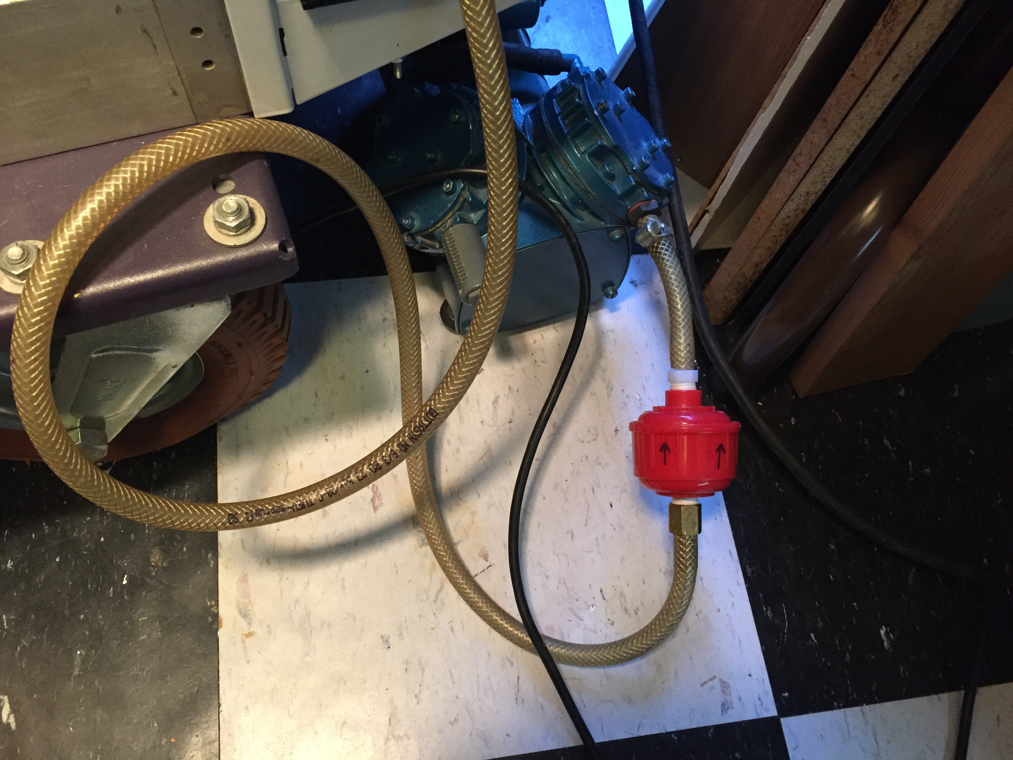
![]()
An air filter keeps the dust from the MDF out of the vacuum pump. Might as well avoid problems before they become a crisis.
So where is the problem?
While the vacuum is sufficient to hold the material in place, I would be happier if it was so strong that it was necessary to introduce bleed air to control the vacuum strength.
When the laser hits this material it is going to chew up the bed, so it will be necessary to replace it ... frequently. Good thing I got a 4' x 8' sheet.
It would be useful to have a ceramic bed made of fire brick or some other material that is tolerant of cutting power of a CO2 laser. No time to mess with it for now.
DIY Space Grade PCBs
3D print circuits using silver ink and ceramic substrates to make high performance, multilayer, fine line < 3mil, PCBs
 The cover sheet used to support the ceramic green tape is still intact. Can it be that the power level of the laser was perfect? Doubtful. If the energy was not absorbed, and the MDF beneath it was not cut then it must have been reflected back. Interesting! Do not look into laser with remaining eye!