Andrew Starr
-
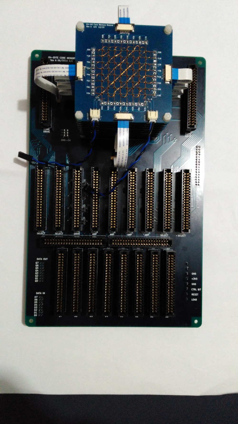
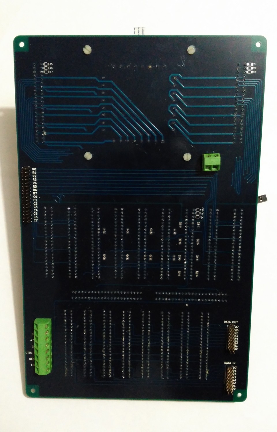
Carrier Board (more or less) Complete
06/29/2016 at 08:55 • 0 commentsJust need to add a few surface mount decoupling caps....and then make a heap of plug-in modules!
![]()
![]()
-
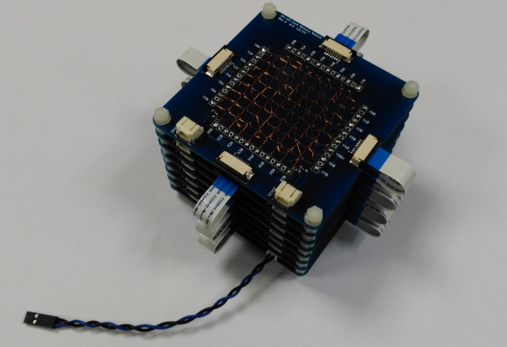
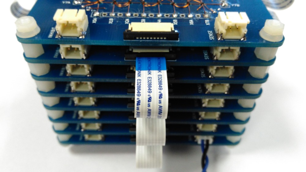
Assembled Stack Test
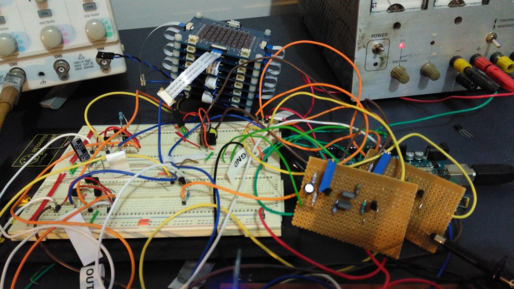
05/18/2016 at 09:31 • 0 commentsI've assembled the first core stack:
![]()
![]()
Preliminary bench testing is encouraging. The stack ran for over 30 minutes writing alternate 1s and 0s to a single byte in the stack without any bit errors.
![]()
I've also tweaked the sense amp design (again) - the two veroboard circuits in the photo below:
![]()
More on the tweaked sense amp later.
-
Sense Amplifier Revisited
05/04/2016 at 08:32 • 0 commentsI was unhappy with the performance of the sense amplifier for several reasons: it required about 30% more current in the drive lines than it should have, it wasn't as sensitive as it should have been, and the signal from one of the pulse transformer secondaries was consistently lower than the other.
After discovering I had the transformer around the wrong way (oops) I was left with an amplifier that still wasn't sensitive enough. I could do better. After considering a few alternatives, I settled on the common base amplifier. It is the least common of the 3 BJT configurations, but I thought it might suit my purpose because it had a) decent voltage gain and b) low input resistance. Low input resistance is important to match the low impedance of the sense coil.
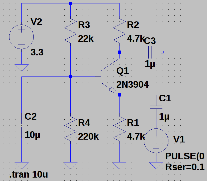
I laid out a design in LTSpice and tweaked it until simulations looked hopeful:
![]()
In a CB amplifier, the base is held fixed and the signal (V1) is applied to the emitter of the transistor. The signal is taken from the collector. The output is rather high impedance, so it would need buffering, before being used to drive the SET line of the output FF. I need 2 of these amplifiers, one for each secondary or the pulse transformer, to catch both positive- and negative-going pulses.
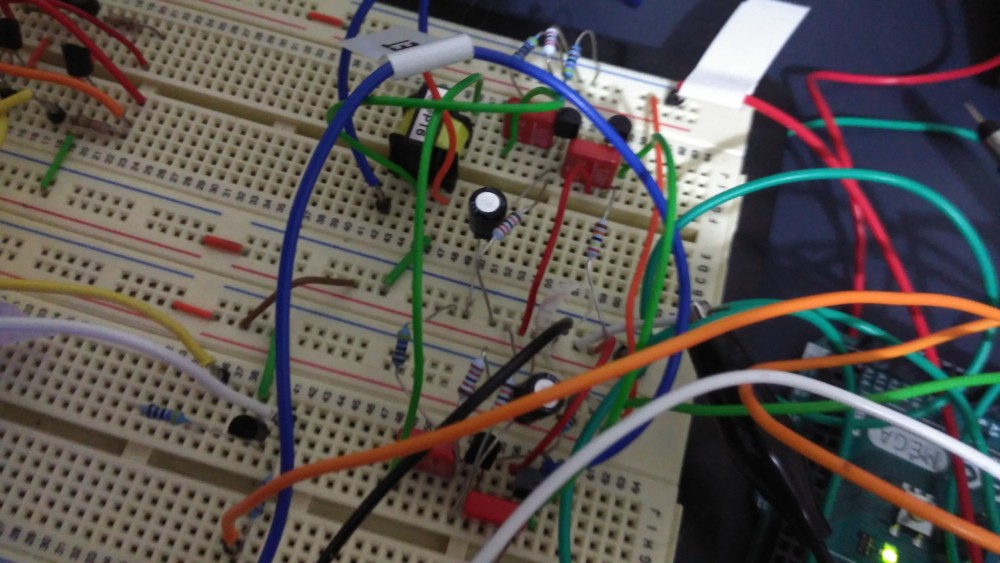
After I was happy with the design, I breadboarded it:
![]()
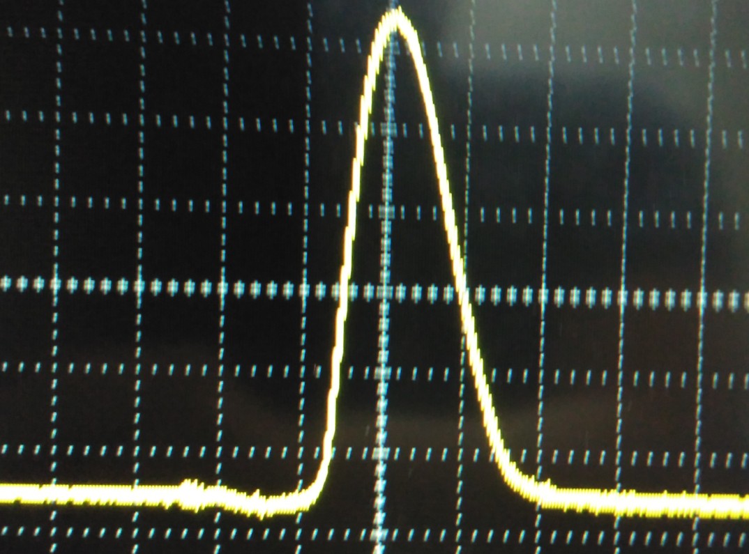
Here is the resulting waveform captured at the output of the CB amplifier:
![]()
About 1V high and 1us wide, at a drive line current of about 250mA. Perfect! Increasing the drive line current to around 300mA did not increase the amplitude, but narrowed the pulse width to about 500ns. Excellent. Next I fed the outputs to the SET line of the FF via two open-collector transistors, and found that the amps were able to toggle the FF on without difficulty.
Now I have to turn the design into a module. I should be able to fit 4 dual-amps on a module, which means I will need 2 modules per memory board.
-
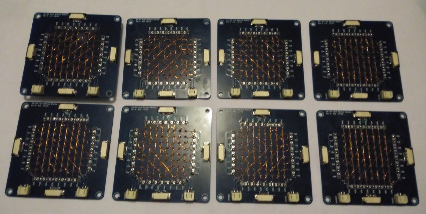
Planes assembled, ready to stack
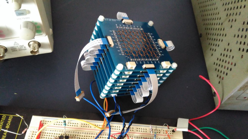
04/27/2016 at 06:43 • 3 commentsI have completed 8 bit planes, ready to assemble into a 8 x 8 x 8 bit (64 byte) stack:
![]()
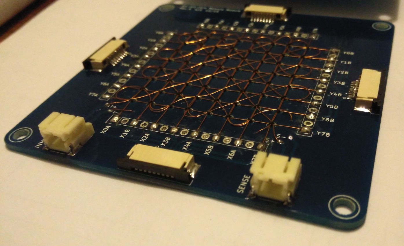
Just waiting on some standoffs, cables and headers. Here's a closeup view of a plane showing the drive line connectors (1mm pitch FFC) and the sense and inhibit connectors (2-pin JST):
![]()
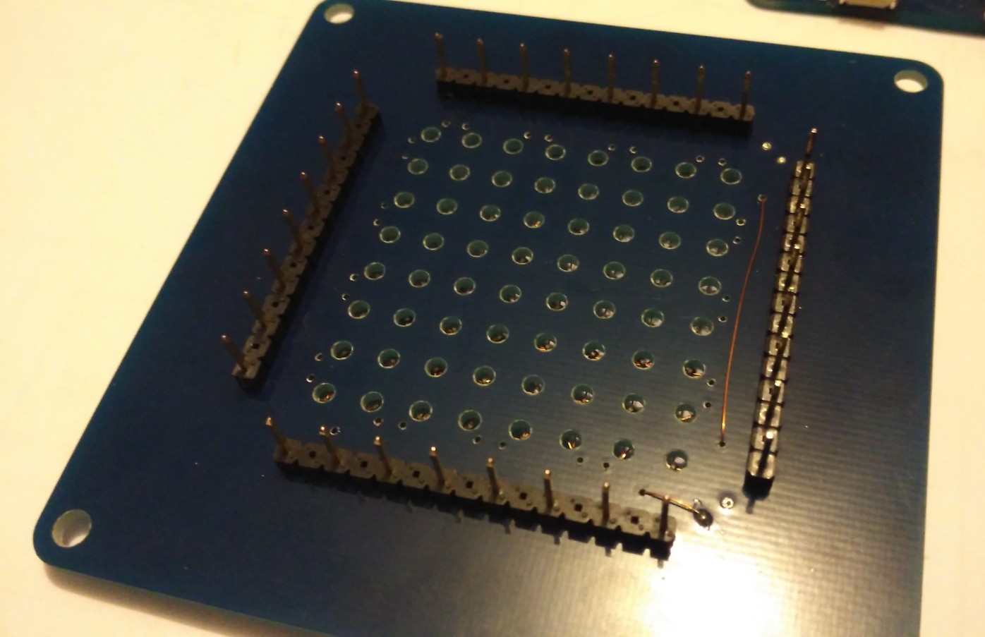
Finally, a view of the underside of the bottom plane, showing the pin connectors that plug into the carrier board:
![]()
Meanwhile, I am workng on the schematic for the carrier board, on which will be mounted the core stack and the logic shown in the diagram in the project details.
Ferrite Core Memory Module
A sub-project of the ED-64 Computer to document the development of a 64-byte ferrite core memory module