 zakqwy
... and it felt great. Made a good bit of progress on the next Phonetroller prototype this evening, starting with some destructive fun:
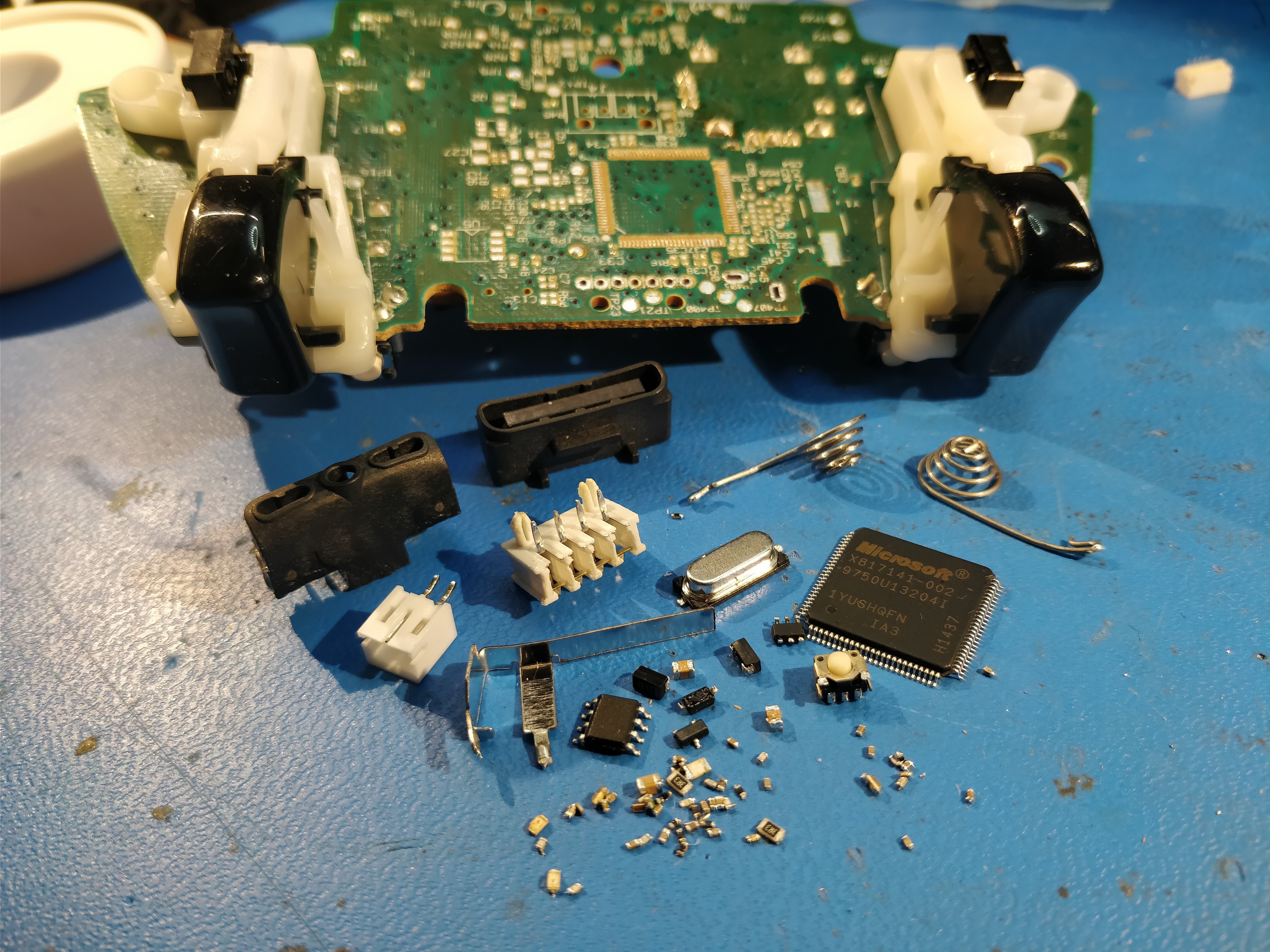
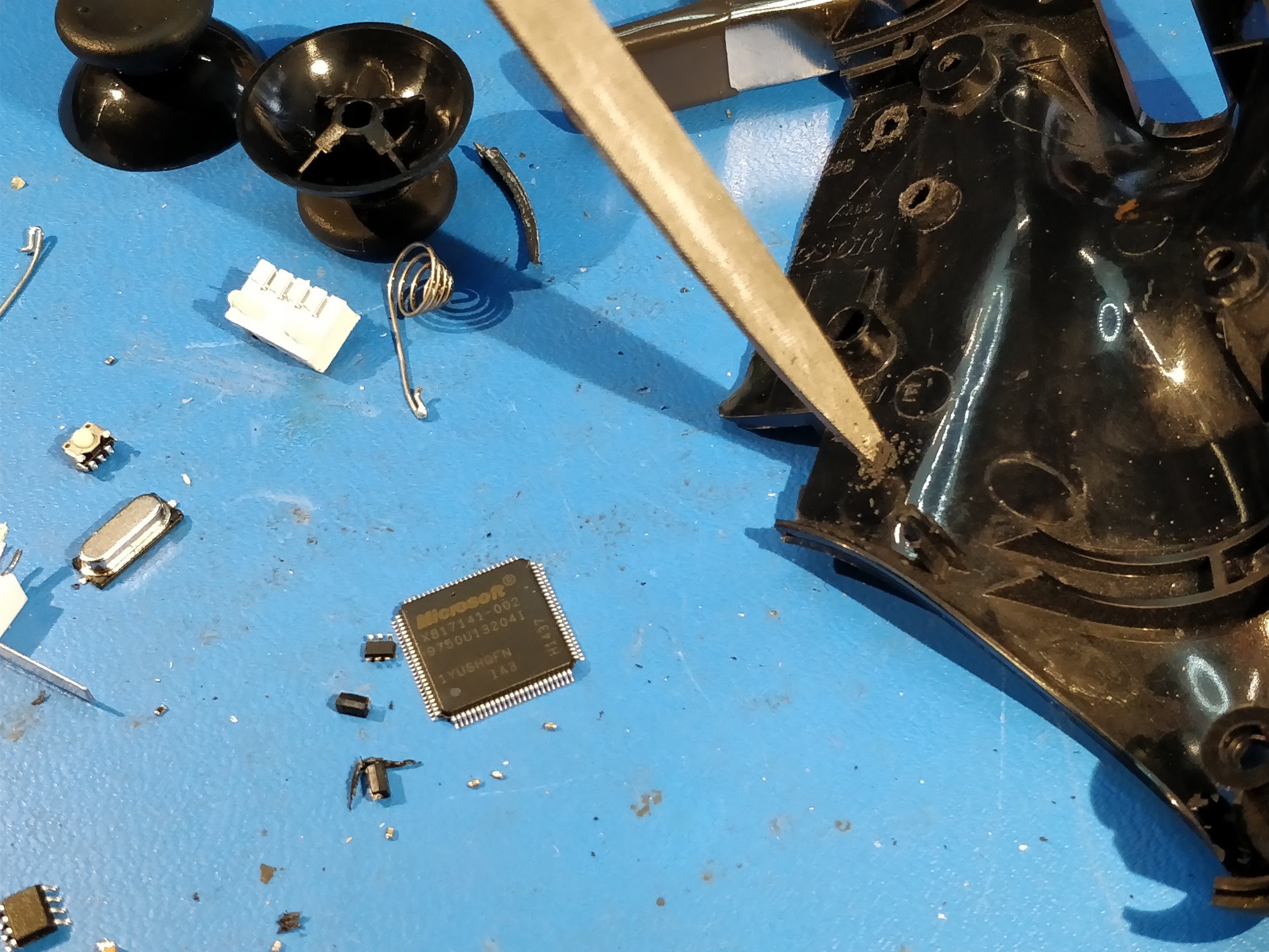
Above, all of the non-control-related (i.e. potentiometers and shoulder switches) parts removed, including that pesky Microsoft-branded wireless SoC. Lots of passives scattered around the board that I probably could have kept, but once the hot air gun starts going it's hard to resist...
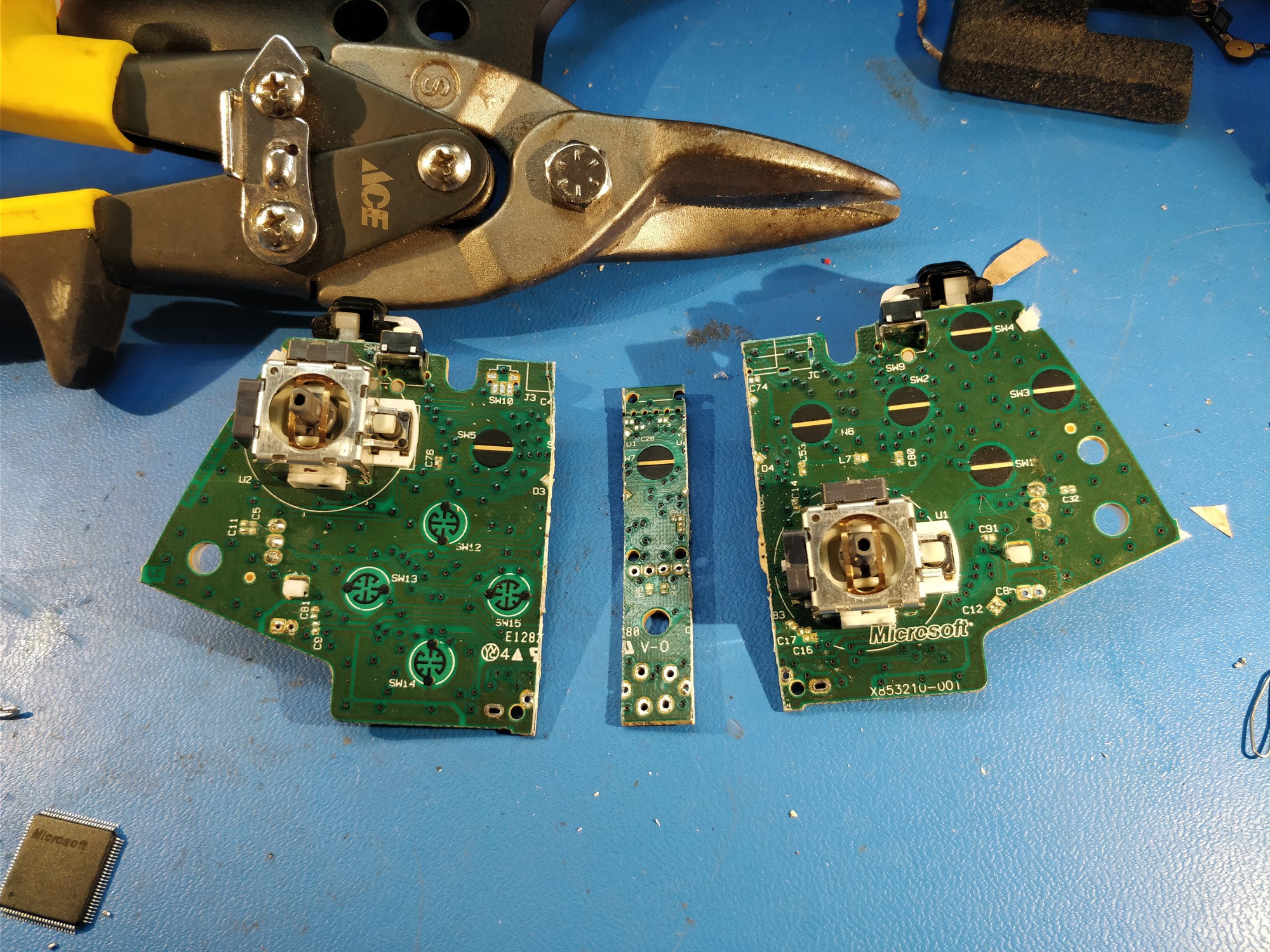
Above, I snipped the board in half and managed to extract a ~12mm strip of unused material from the middle. The PCB is some kind of phenolic that tends to shatter a bit, so I scored it first and had to clean the cut up with some sandpaper afterwards.
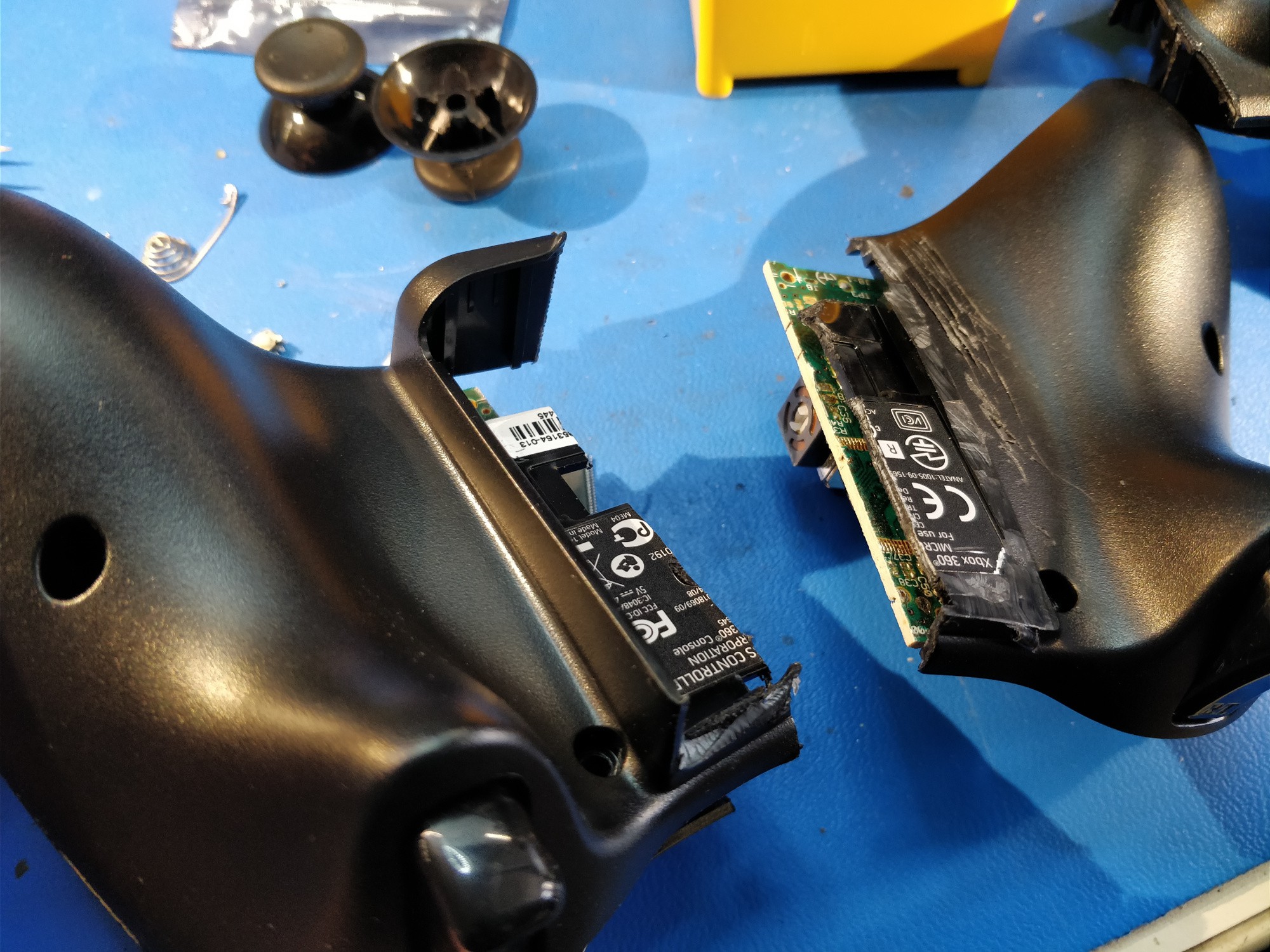
Above, test-fitting the boards after slicing the controller's ABS shell in half. I started fiddling around with phone position around this point, and ended up trimming the plastic battery case remnants off the back (as seen on the right).
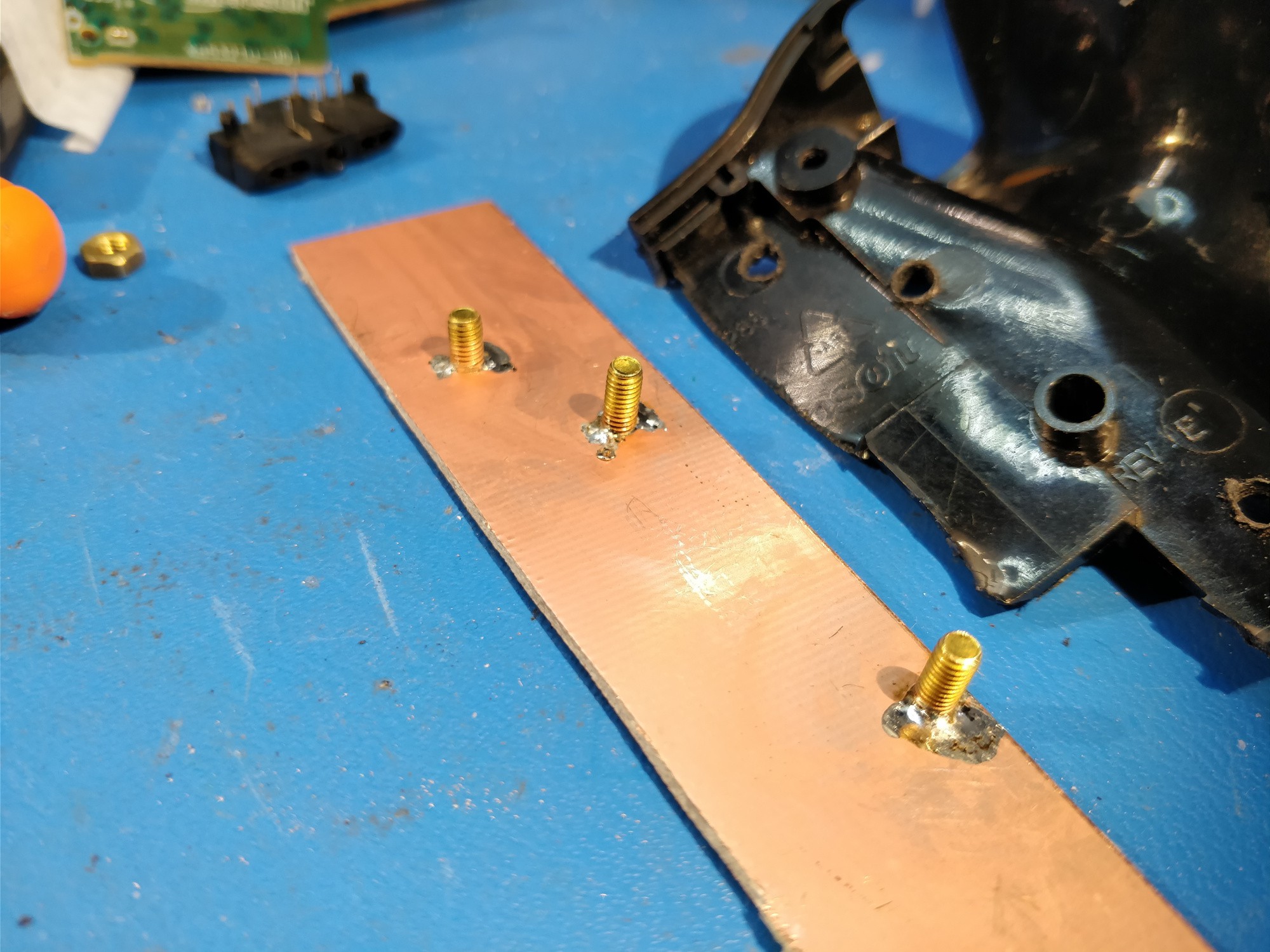
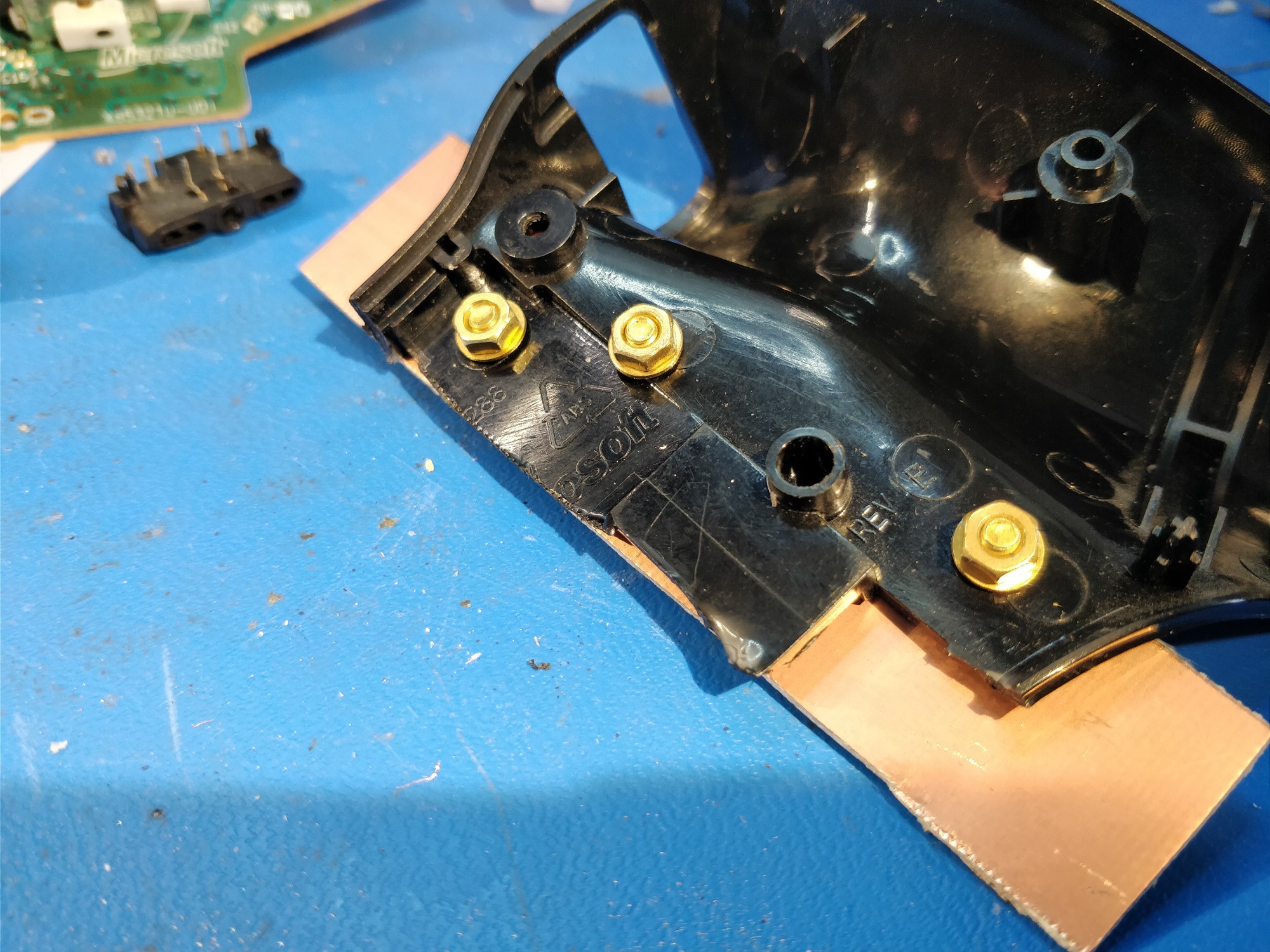
Above, I soldered a few cut down brass M3 machine screws to a piece of FR4. It would probably be easier to just glue the boards to the ABS shells, but this way everything is removable and much easier to work on.
Above, drilling mounting holes with a crappy file. Might be time to bring a drill in to the lab.
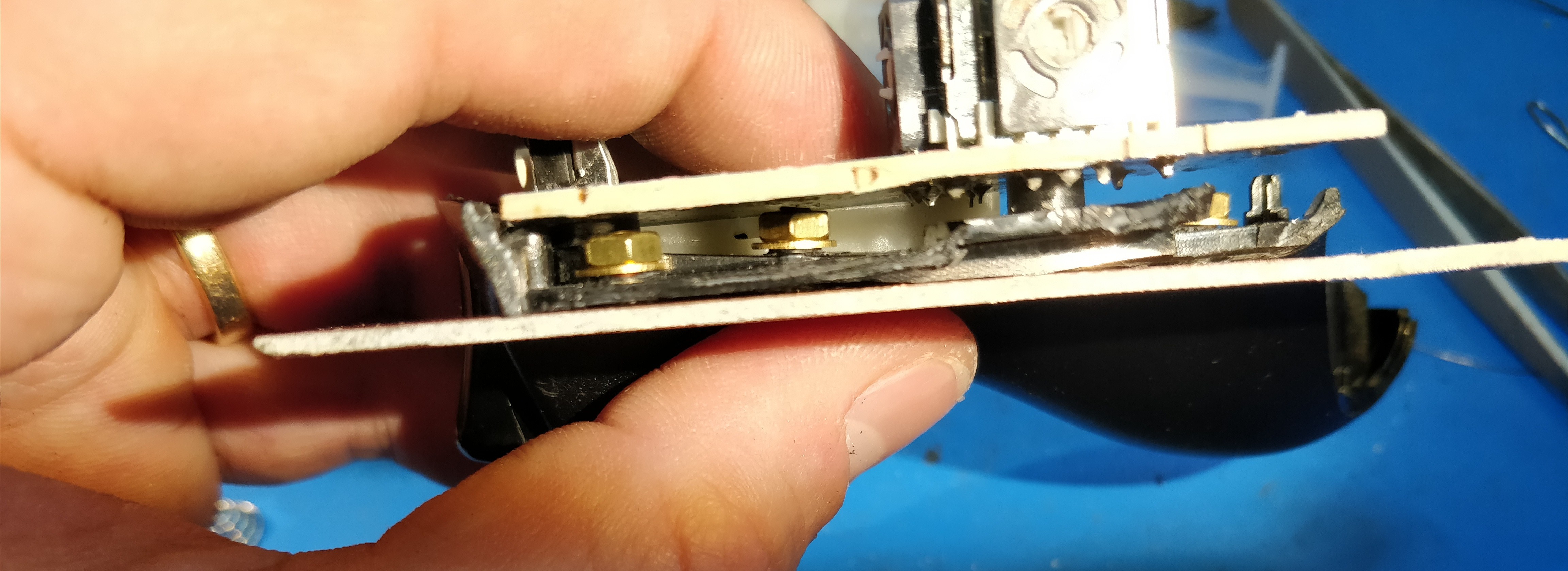
Above, success! And surprisingly strong.
Plenty of clearance!
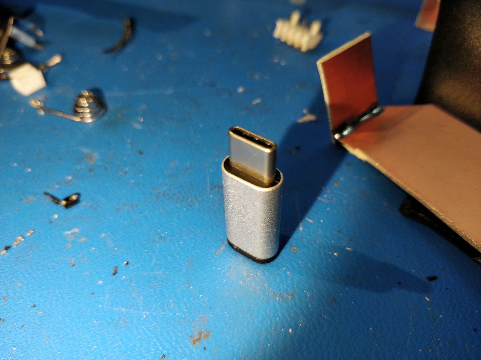
I had a uUSB to USB-C adapter lying around from the original Phonetroller prototype (when I bought a few at a local store). Time for more destruction!
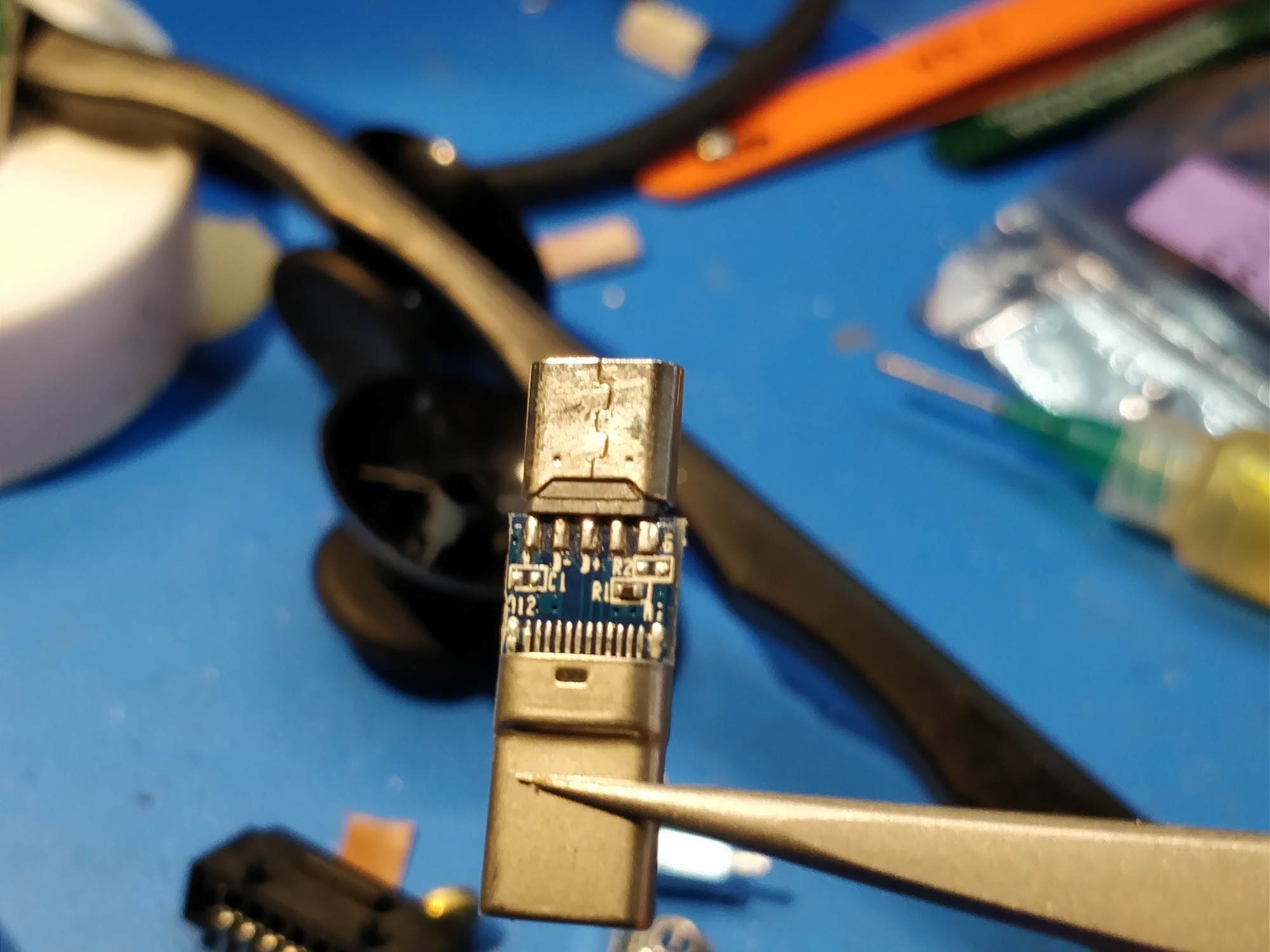 Above, another nicely labelled PCB. R1 and R2 are for CC-1 pulldown and pullup, so this board can actually be used for a host or device. I ended up having to swap the resistor for a 5k one, otherwise 5V didn't appear on the VBUS line. Yeah I don't really want to read the USB-C spec, but this seemed to work.
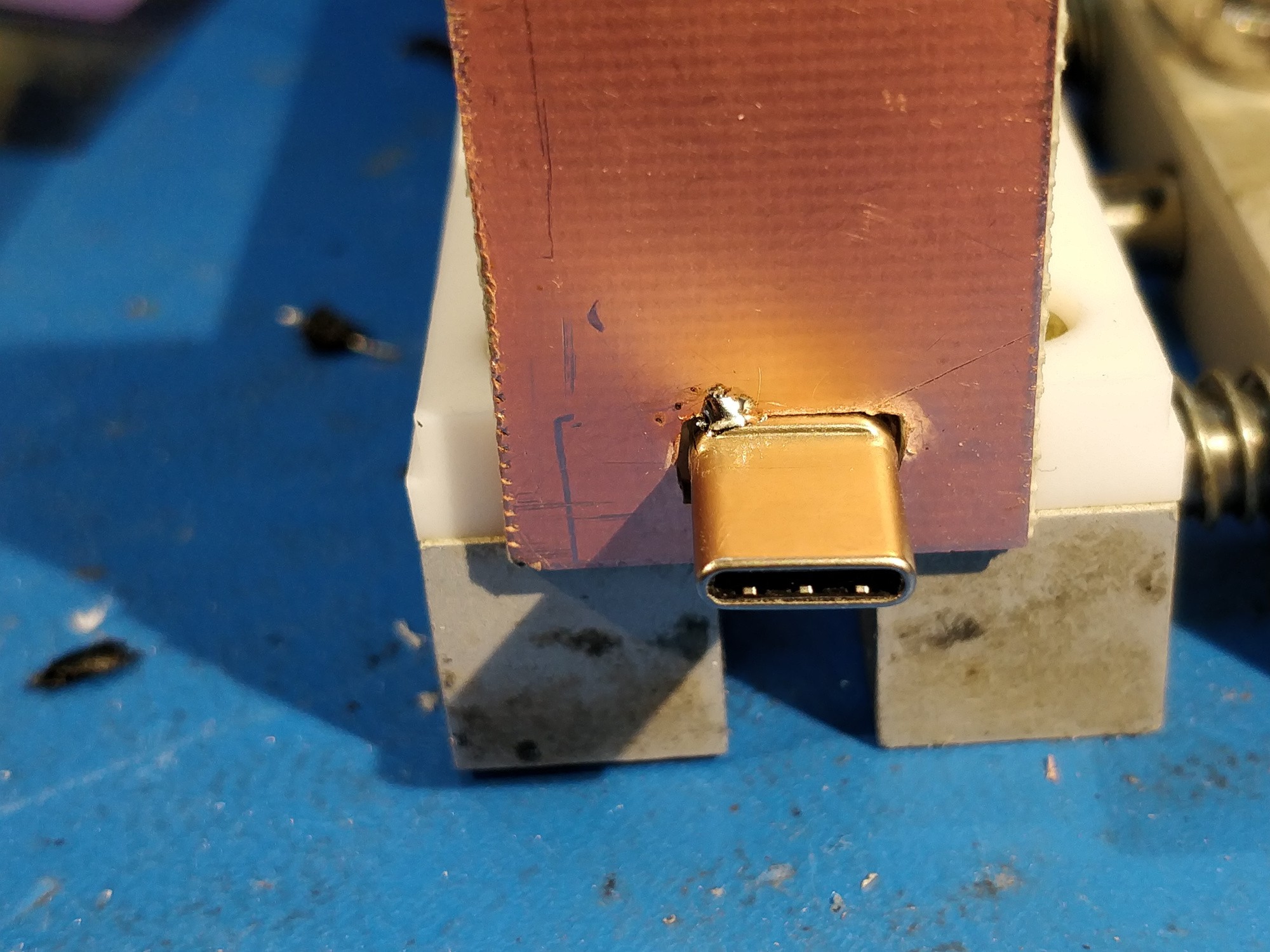
Above, more bodgy file drilling. I tacked the USB connector shell in place after adjusting the insertion depth using my phone (in its case).
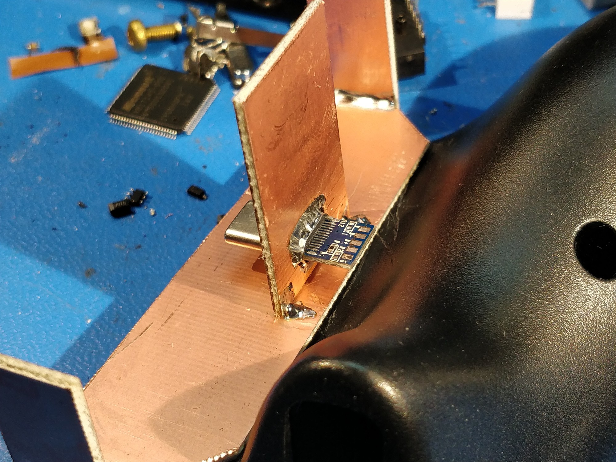
Above, some severe USB-C connector abuse. The shells solder nicely and transform into quite robust dock connectors.
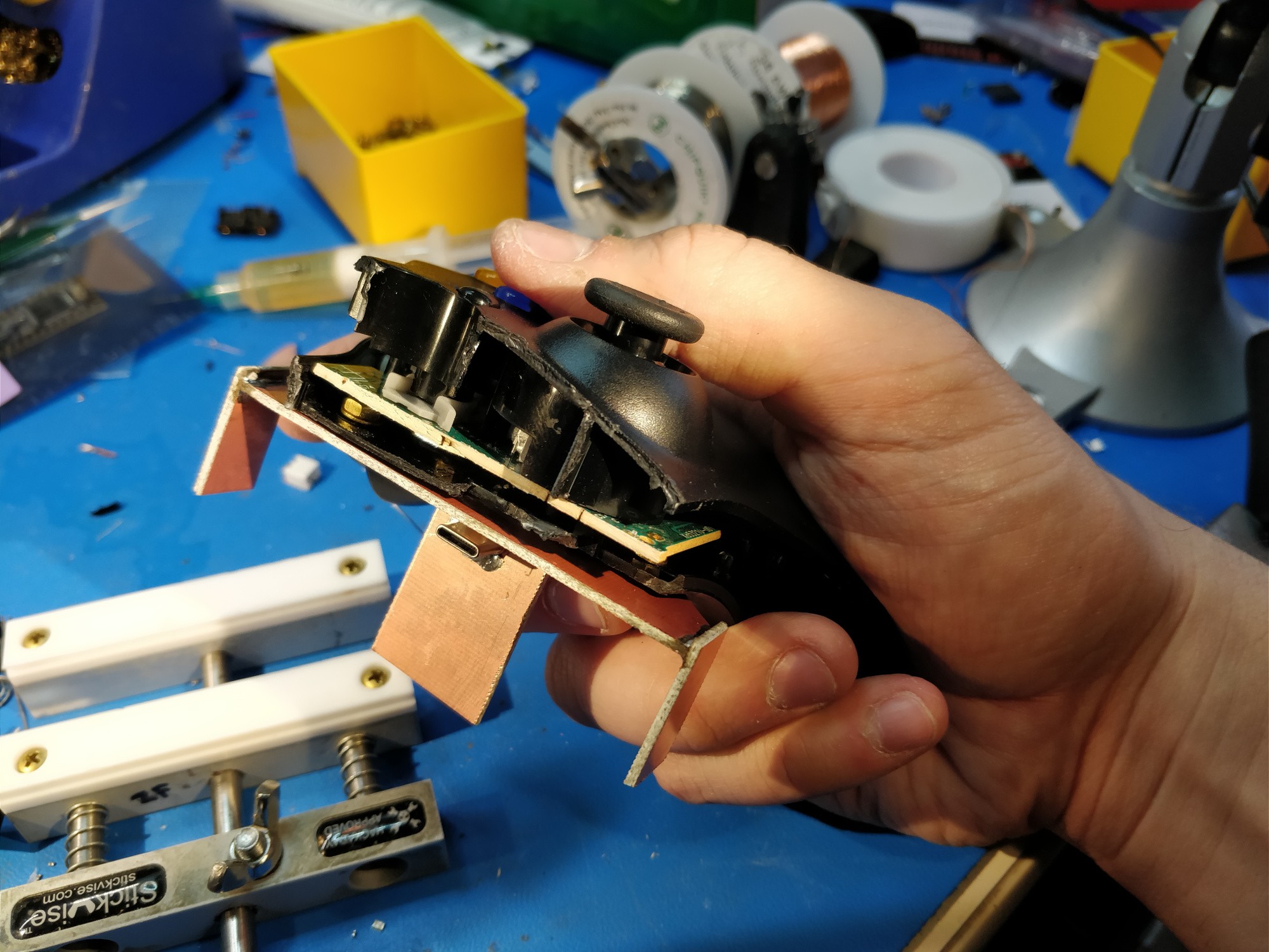
Above, test fitting the works together.
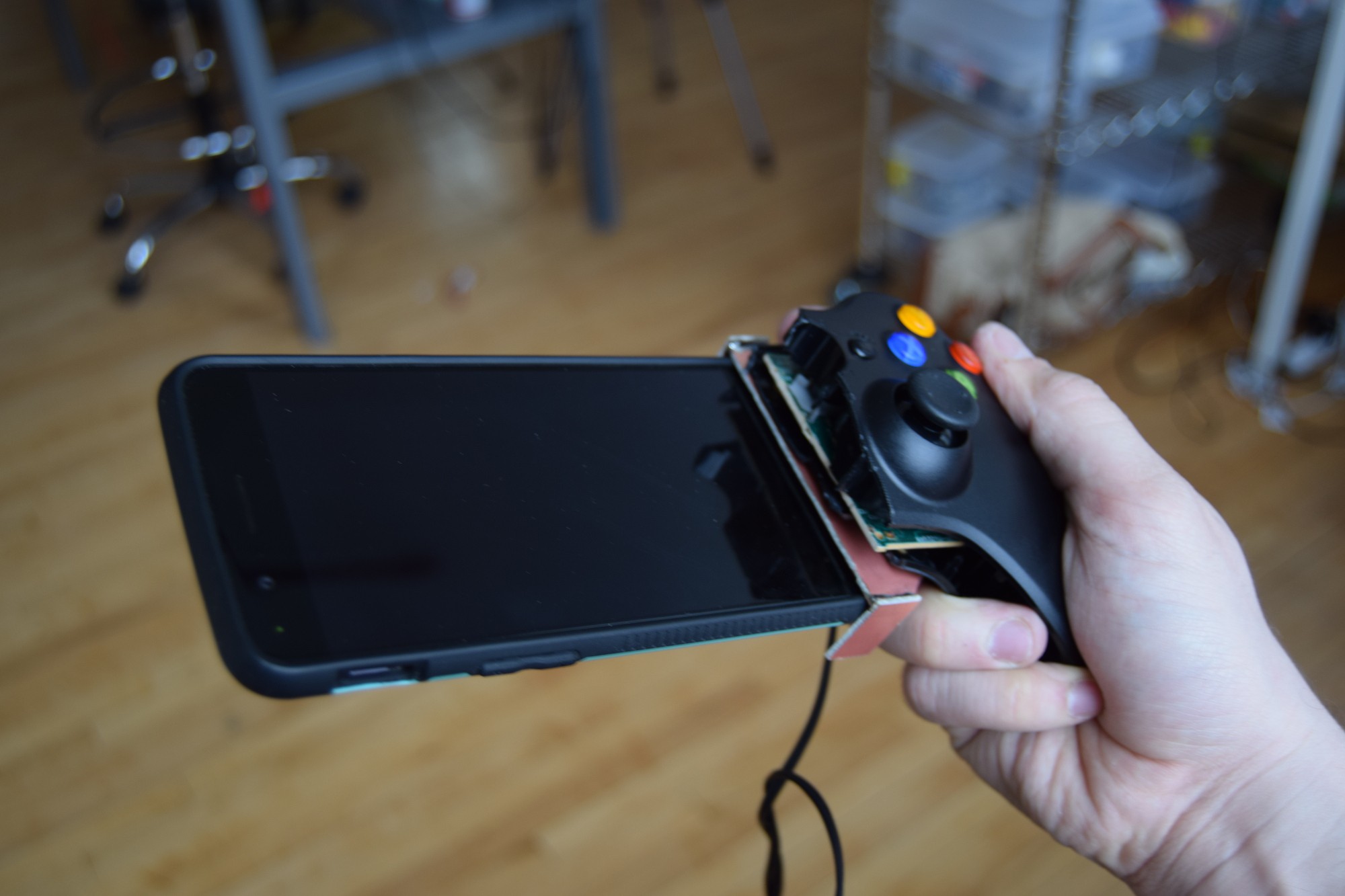
Above, a blurry picture (mostly because DSLRs don't like to be used one-handed from the left side) of the phone test-fit on the controller for the first time. The back plate isn't in place so this is a bit wobbly, but the friction from the side panels and the connector itself were more than sufficient to keep it from falling out.
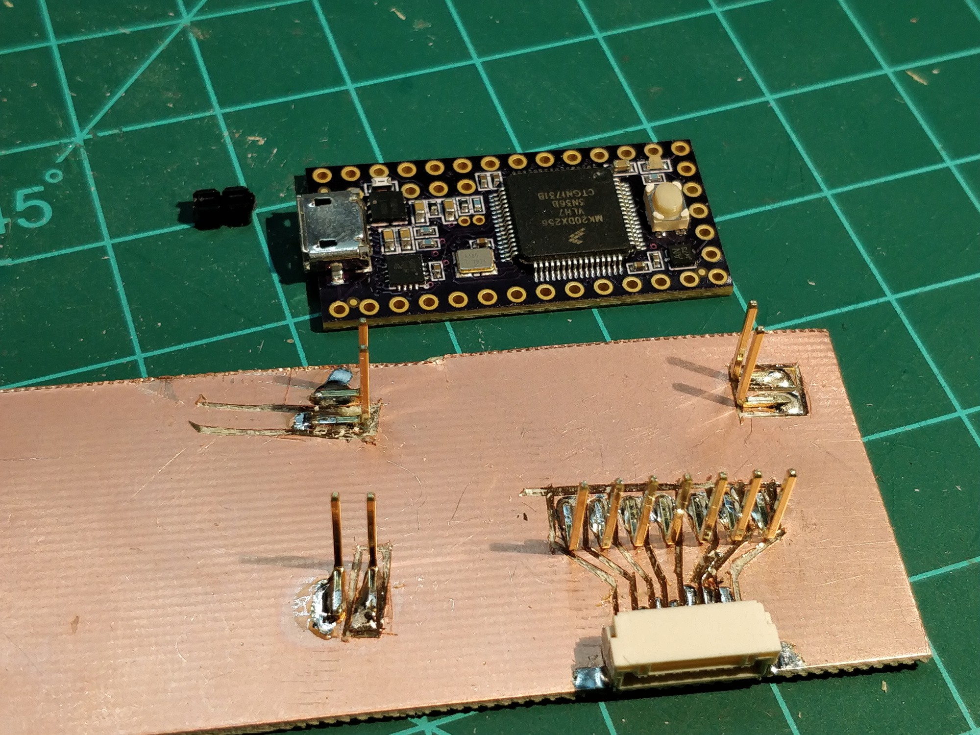
Above, starting to carve up the control board that will fit under the phone. This board will be on the righthand side (as with the original), so it needs signal wires to pick up the lefthand controls. 12 conductors needed total: power, ground, 3 potentiometer wipers, and seven buttons. The 7-pin JST GH takes care of the latter; I took the time to 'route' this bit to save on wire jumble.

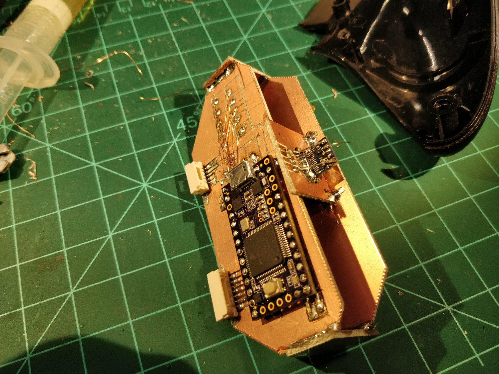
Above, the 5-pin JST connector has been added along with a bunch of 34AWG magnet wire. Note the ten pads at the top -- these are breakouts for the right side controls (also 7 buttons + 3 pots), so I can land them in an intermediary spot after securing the Teensy.
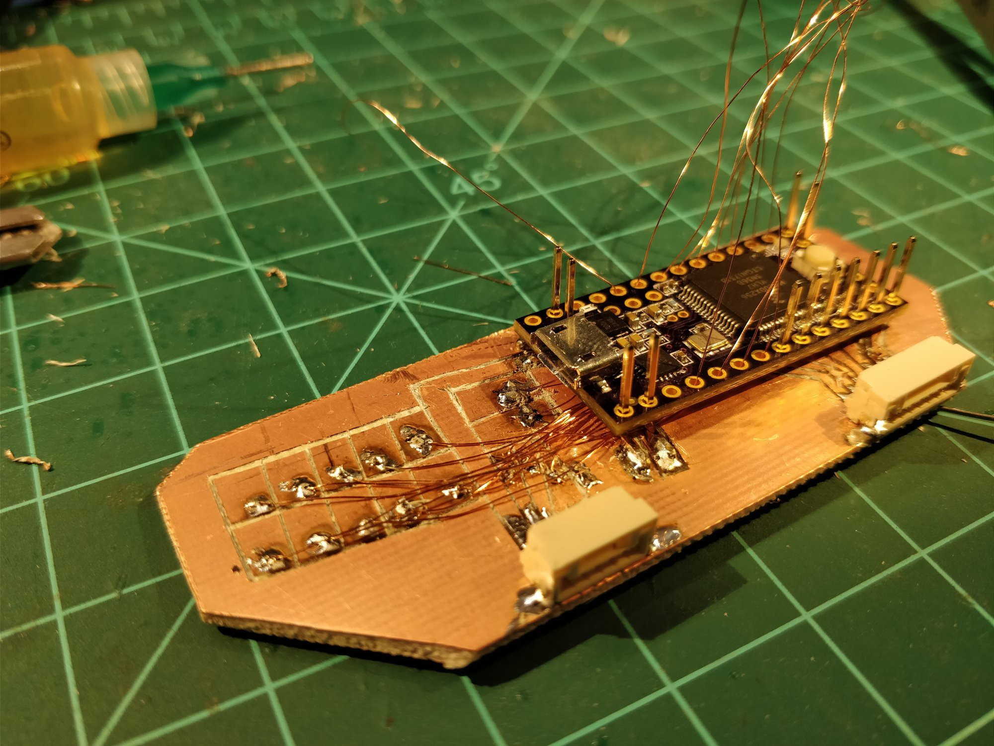
Above, this part gets a bit chaotic. The key is to allow a good bit of extra wire so everything can be threaded before soldering. Also note that I broke out the USB D+ and D- pins to their own pads (directly in front of the uUSB connector) -- quite important, as they are only accessible via rear SMD pads!
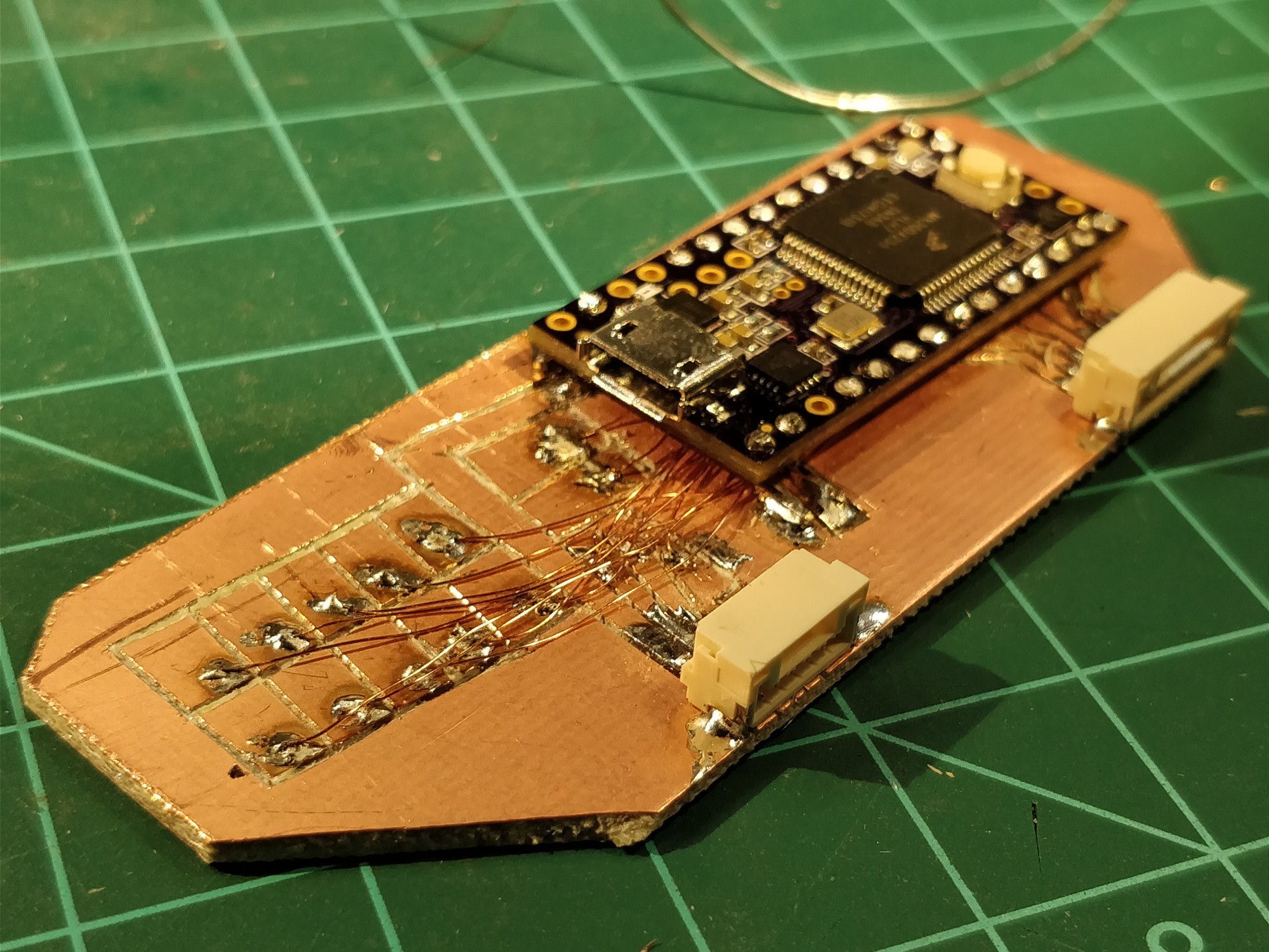
Soldered and trimmed. The wires tuck nicely under the processor board; a bit of conformal coating will keep them protected and secured once everything is tested.
Above, the rear board is mounted to the rest of the assembly after another round of test-fitting with the phone (which was used to take this and most of the other pictures).

Above, a back-to-back comparison with the original Phonetroller righthand board.
So. A lot of progress tonight. Still to do:
- modify the lefthand shell to accept a PCB mount
- construct the lefthand phone cradle
- carve the lefthand PCB
- break out the various connections on the (now two) XBOX PCBs
- f-f-f-f-f-firmware! (which should be a fairly simple port from the Phonetroller I).
I also spent a bit of time last week sketching out some larger picture concepts in my notebook. I think I have a few ideas for a more refined and kit-able version -- something that doesn't require quite so much customization to fit a given phone. More to come.
Discussions
Become a Hackaday.io Member
Create an account to leave a comment. Already have an account? Log In.