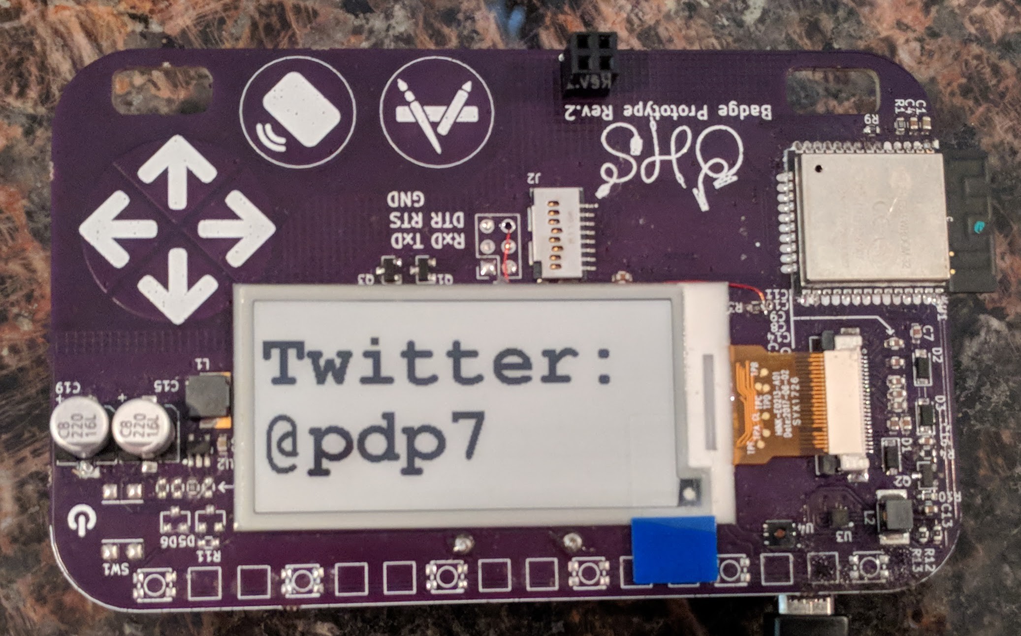
The official firmware will be MicroPython-based. However, I wanted to document an Arduino sketch and libraries that can be with the e-paper display on the bage.
The GitHub repo is here:
https://github.com/oshwabadge2018/arduino-epaper-demo
Instructions:
- Install the latest Arduino IDE and add the ESP32 board options to the Board Manager:
- Make sure the board is set to "ESP32 dev module"
- Make sure the serial port is the serial adapter.
- Wire up GND, RX, TX to the FTDI.
- Connect the IO0 pin to GND.
- Insert Batteries
- The module should power up and go into programming mode (IO0 low on powerup or reset)
- Click program in the Arduino IDE.
- The board should program.
- Un-ground IO0 and remove and reinsert the batteries.
- If this does not work then swap RX and TX and repeat the process
Methods to connect the wires:
- remove battery back to expose the bottom of J1 header and solder a 6 pin header on J1
- solder wires to J1 on the front the badge (and leave battery pack in place)
- use a 6 pin pogo pin adapter. I used an AVR ISP pogo pin adapter and connected to an 3.3V FTDI cable from Adafruit
- gallery of photos: https://photos.app.goo.gl/rP3fTZDd6UUGbDtt9
(I may try to do a diagram in the future, but wanted to link to photos in the meantime)
 oshpark
Discussions
Become a Hackaday.io Member
Create an account to leave a comment. Already have an account? Log In.