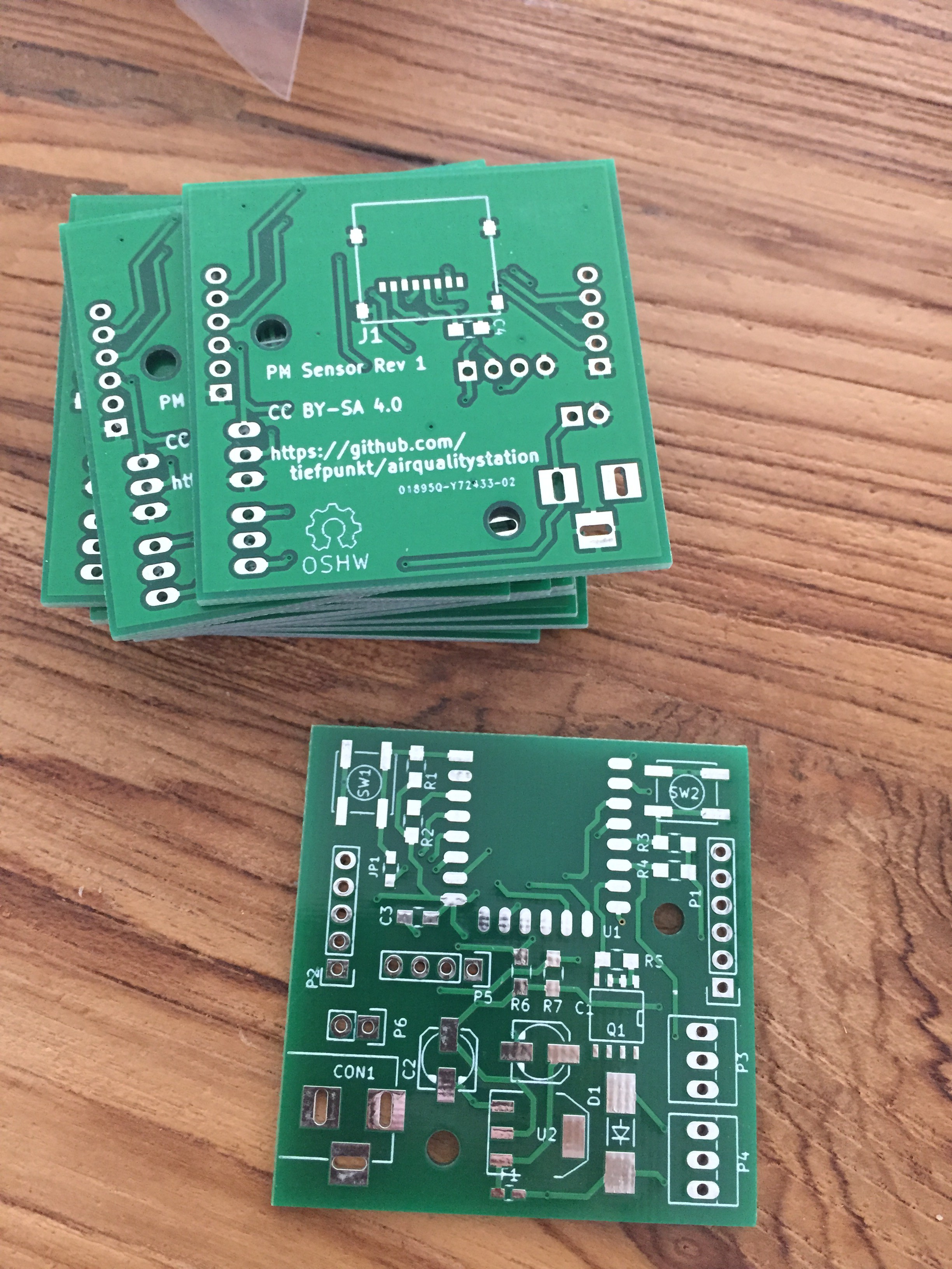
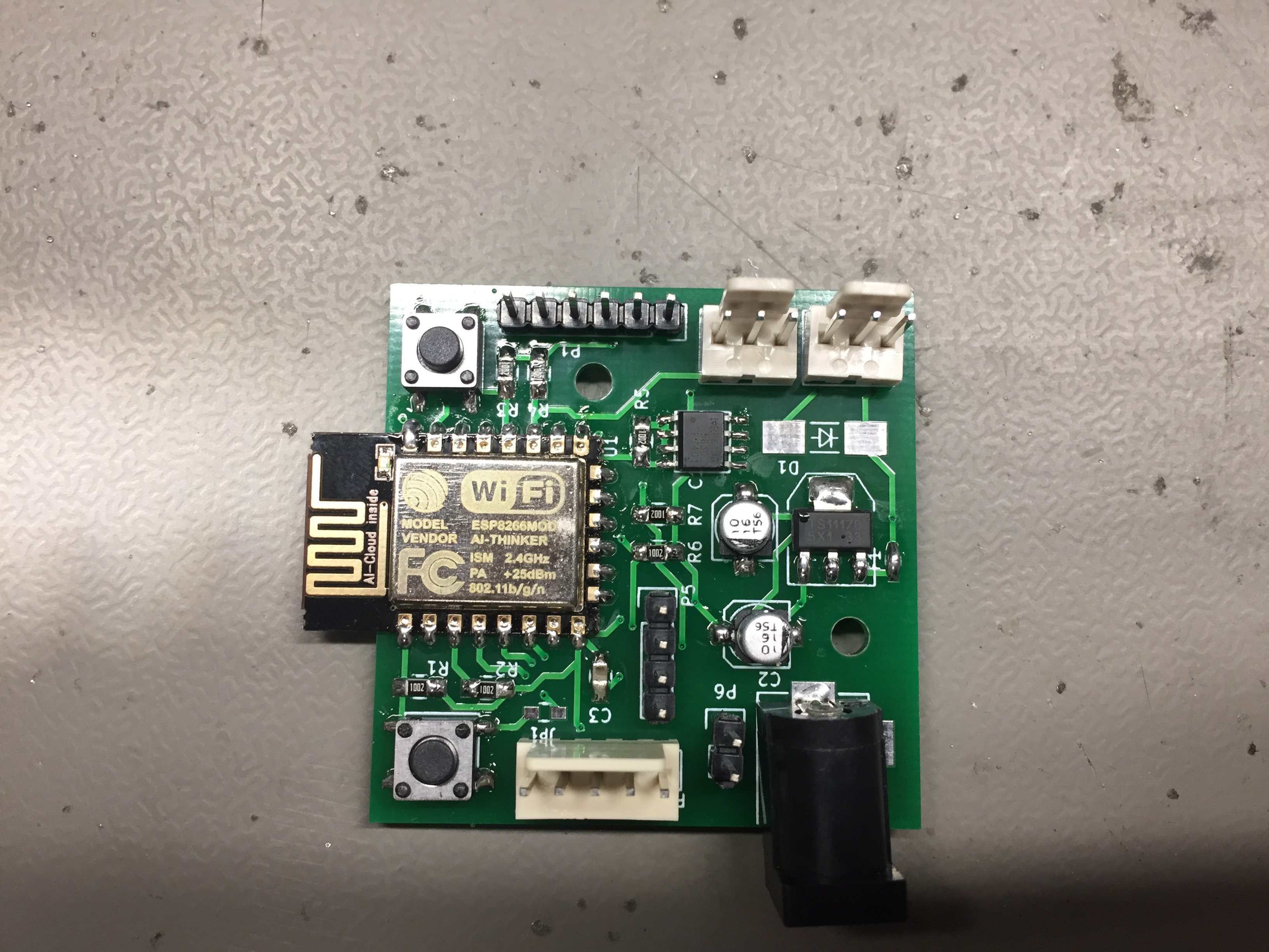
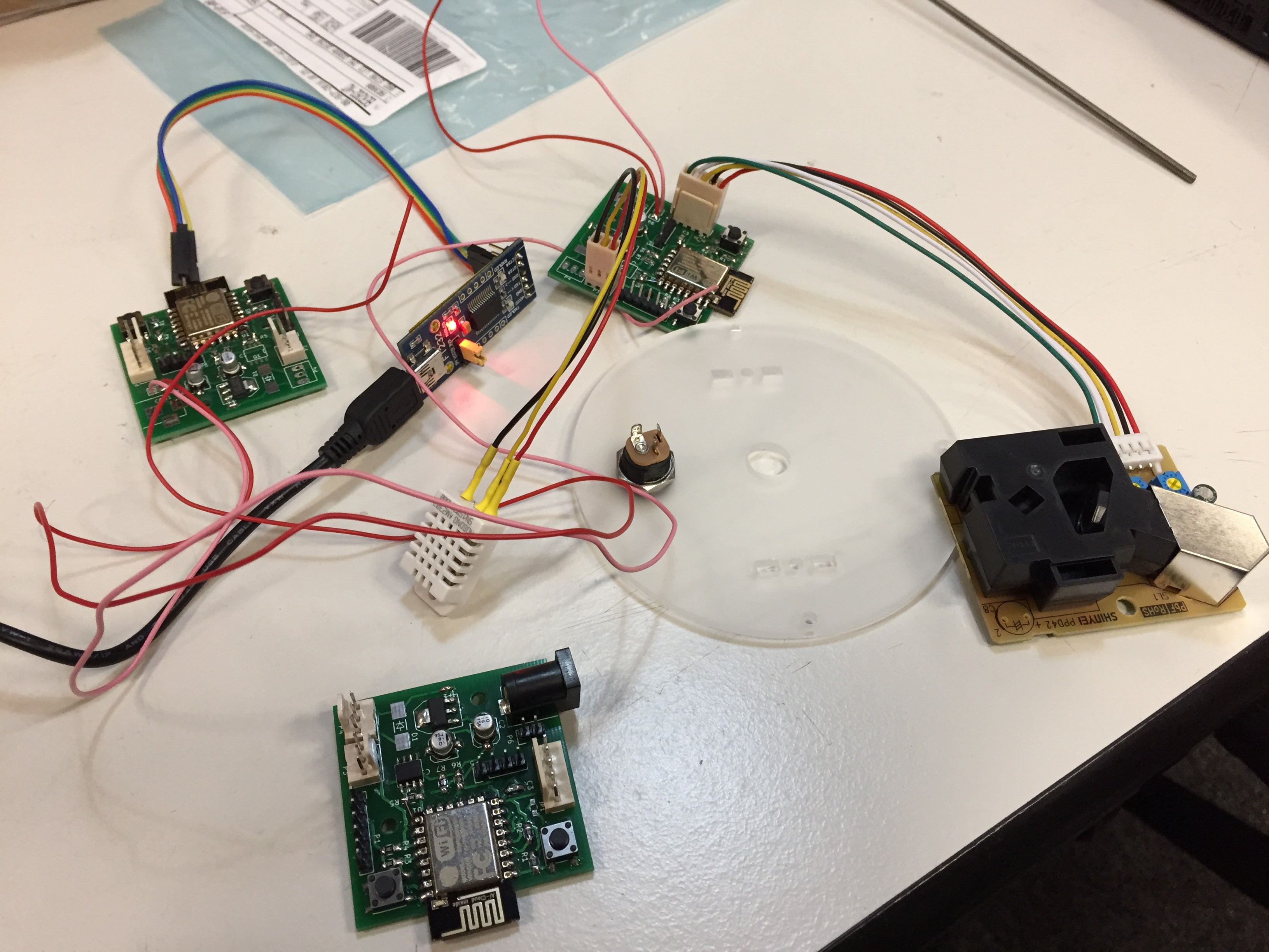
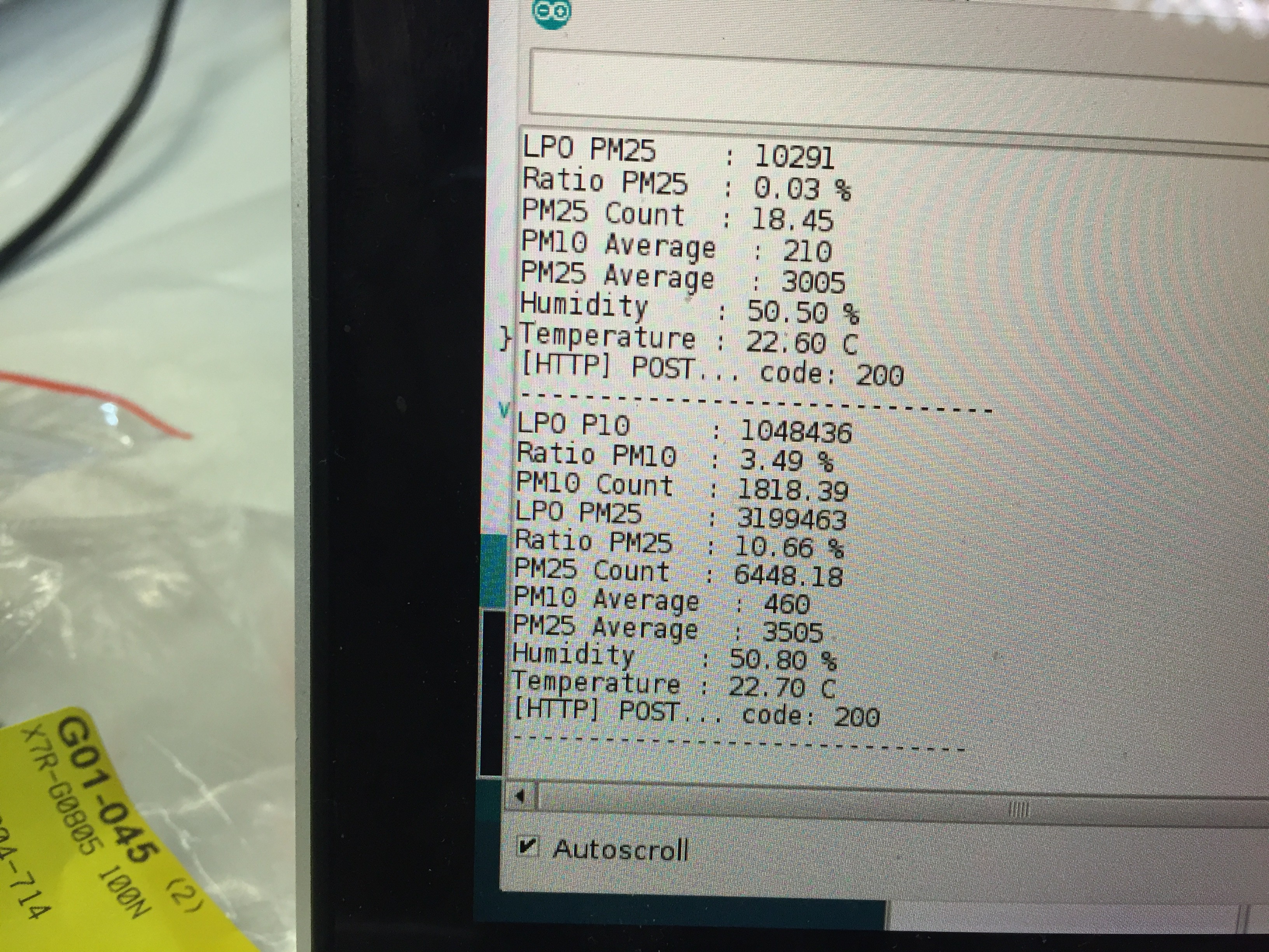
Having settled on a sensor and gotten pretty much the data that we wanted, it was time to get some PCBs made. This isn't something I do regularly, so it took me quite a while (and quite a bit of kicking my own butt) to fire up KiCad, and make this PCB. I designed the circuit with a few extentions in mind, such as a MicroSD card slot, a MOSFET and connector to connect a fan, and an I2C connector. I got the board made alongside with another project at SeeedStudio. They had done another board for me quite a while ago, so they were my first choice. Fast forward 3 weeks, and I had 10 boards on my hand.
Test assembling one board, the ESP did not start properly. It started up fine once I put it into flashing mode, then I could program it via the FTDI header, but right after it went back to not doing anything again. Resoldering the ESP didn't fix much, but after looking closer at the PCD design and poking around the board on the pins responsible for setting the boot mode, we figured out that I had missed a ground connection on one of the pull down resistors. That was a quick fix with a bit of bare wire, and everything was booting fine.
I noticed two other mistakes. I had screwed up the pin order on the fan connector, and the silk screen for the connector of the DHT22 was the wrong way around. We didn't end up using the fan at all yet, so no harm on that side. And the DHT22 connector was quickly desoldered and turned around, so that didn't do much harm.
 tiefpunkt


Discussions
Become a Hackaday.io Member
Create an account to leave a comment. Already have an account? Log In.