 T. B. Trzepacz
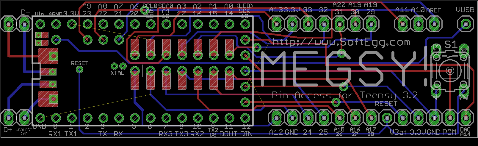
While there is the official PJRC solution to this problem, it does involve buying a lot of fiddly surface mount components that I am not confident in my ability to mount without destroying them. So I feel that this project still has some value.
I realized that I will probably need an external USB port at some point, so I needed to add those lines in an easily accessible way. While I was at it, I added some form of access for every signal on the bottom of the board. On the off chance that one decides that they need the crystal, I made through holes for that. Not every signal has a pin, but I think everything has exactly as much access as is neeed
Also, I decided that I should really work to make the pads and via placement more accurate, so I started with an image of the Teensy 3.2 PCB and carefully measured everything in Photoshop once I got the grid all lined up correctly.
I left the through holes on the bottom as per the original Eagle part, so you could still theoretically use it with a two row header if you want. I think my plan of the "poor man's BGA" will be the best way to use it, however.
I also ran design rules check (DRC) for the OtherMill on it, and other than a few of the through-holes being too small, it now passes. There is some flagging for overlap, but I did that overlap intentionally, so hopefully the software will be able to handle that.
The entire thing now needs about 60 pins to mount. Which is fine for a breadboard. If you wanted to socket it, you'd need a 32 pin and a 26 (or 28) pin socket. I think those are actually things that you can get.
Now I just have to decide whether to send it off for manufacturing, or wait and try to do it when I get access to a mill?
Discussions
Become a Hackaday.io Member
Create an account to leave a comment. Already have an account? Log In.