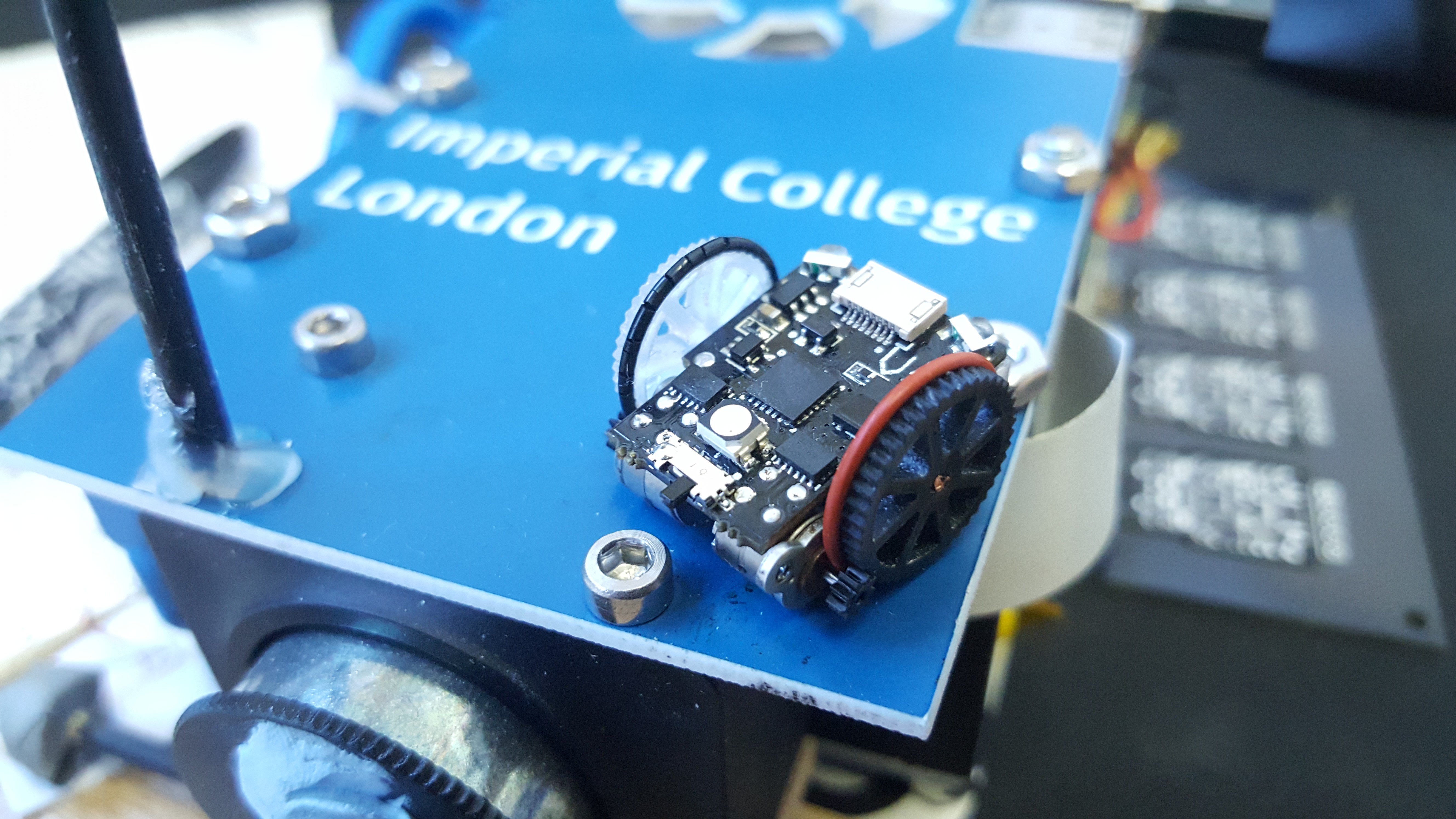
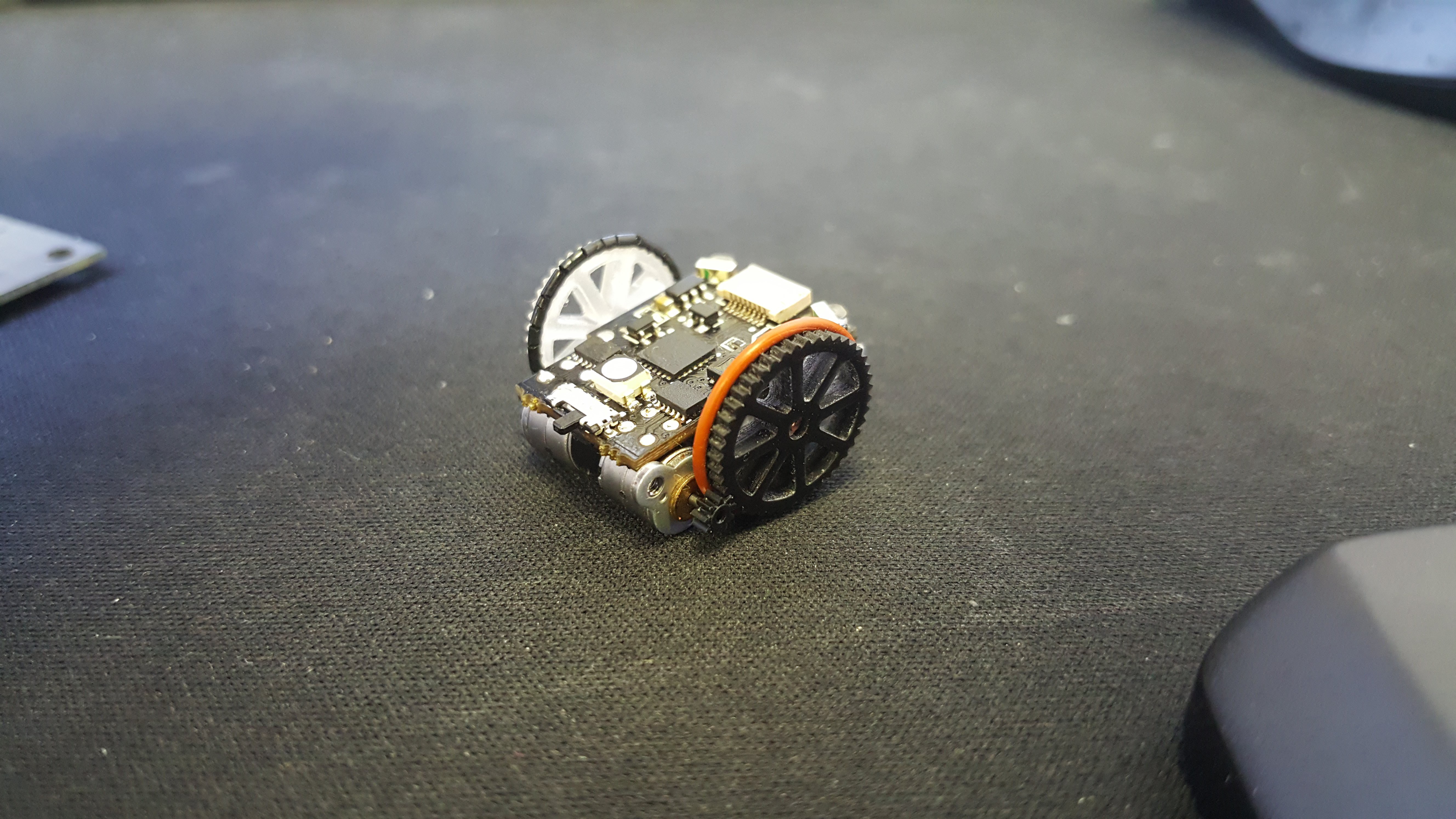
Hello everybody. V4 is alive and well. Below are a few upgrades we have implemented.
- Upgraded to STM32F0 processor. 48Mhz lots of nice peripherals 32k program memory and 4k SRAM, not to shabby.
- Front facing sensors are now a type that actually face forwards, therefore we no longer need optics to redirect the light into them.
- The single upright pin from the previous design is now a 2 upright pins. These are used for on-the-fly charging. Bump into 5v and charge away. They are reverse polarity protected. So don't live your life in fear.
- The programming header can now be plugged in backwards. It won't function the wrong way around, but it won't explode either.
- The 'hips' of the robot have been shifted inwards to account for the face plate of the motors. This allows the wheels to run much closer to the robot's main board and make the footprint even smaller.
- The upgraded processor has enough PWM pins (which are correctly connected) to implement phase control of the motors, as per 'micro-stepping'. This allow the robot to turn the motors slowly without introducing large vibrations that cause the robot (V3) to lose traction.
- The wheels have been improved (Not strictly an upgrade to the PCB design, though I care about wheels too much to leave them out).
So this version is significantly better. Though every design needs an appropriate erata! Things that are wrong:
- The IR reciever IC is connected to a poor pin on the uController. This means we cannot use the hardware UART to recieve serial. Also the particular timer on that pin is not sophisticated enough to implement the best version of the library that recieves remote controller commands. So in general communication to the robot is now awkward.
- One of the front IR sensors is not connected to an ADC pin. Rendering it basically useless, unless your light levels are such that the digital threshold happens to be correct.
- Whilst not breaking the design, due to the keep out area allowing the axle to pass through, there are too many components near to the battery terminal. This makes soldering in the battery a dicey business. You are only ever 8mil or so away from shorting the LiPo battery out and causing a fire. This will be solved by splitting the axle in two. Using an 'L' shaped piece of wire one limb will be the shaft and the other will be the upright pin for charging purposes. This also means that charging pins coming from the centre of the wheels on the side is also an option. (Makes me think of the chariots from "Gladiator")
Below are some videos and pictures of the newest version for your viewing pleasure.


 Joshua Elsdon
Discussions
Become a Hackaday.io Member
Create an account to leave a comment. Already have an account? Log In.
Nice to see the project progressing. A shame about the pins -- is it just a bad choice, or did you run out of pins that could be used?
I wonder if it would be possible to break out some of the free pins to a pin header on top, so that you could have "shields" with additional sensors or effectors.
Are you sure? yes | no