-
Automated refuelling: Early Test.
06/17/2016 at 20:15 • 0 commentsHello.
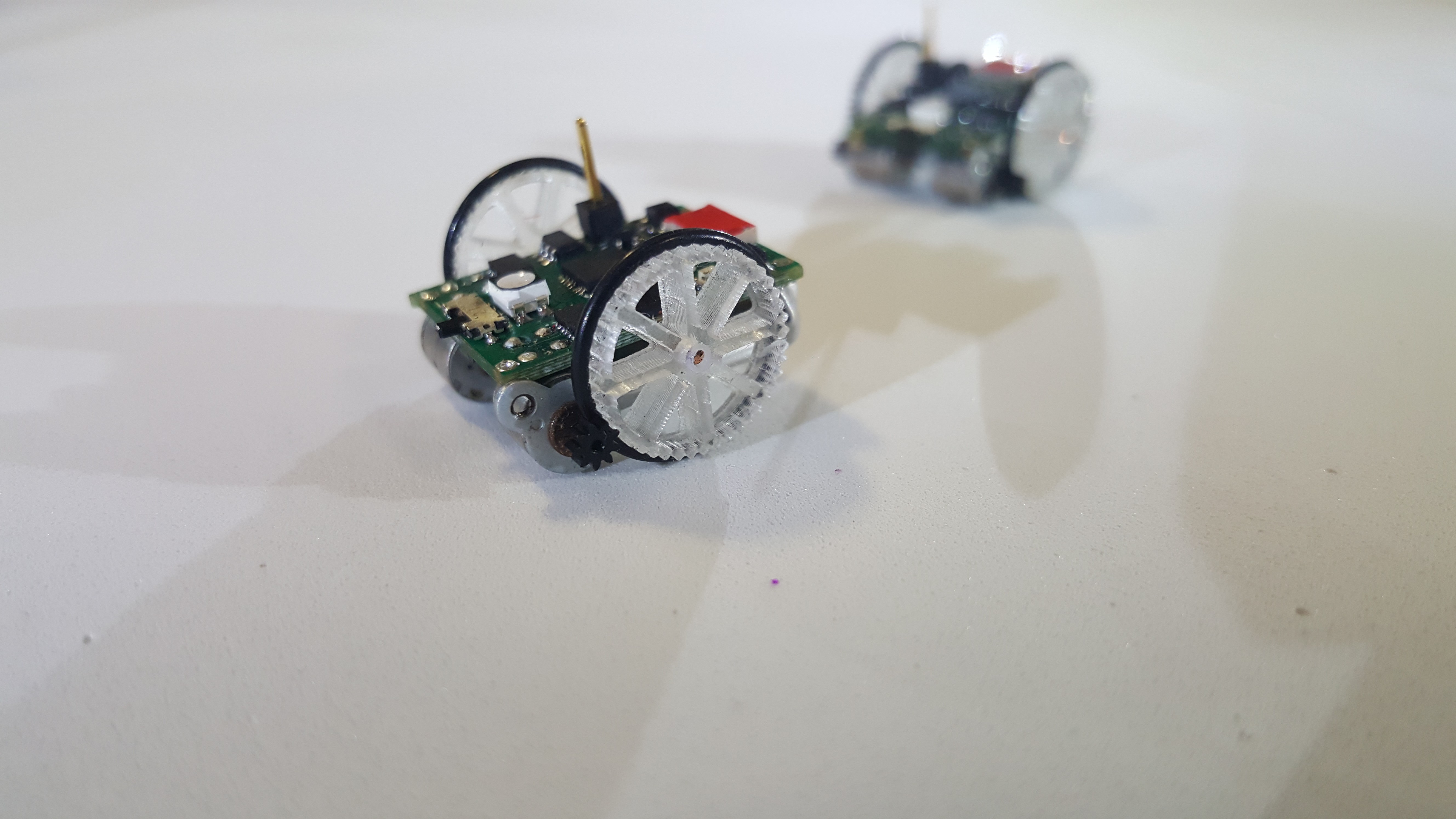
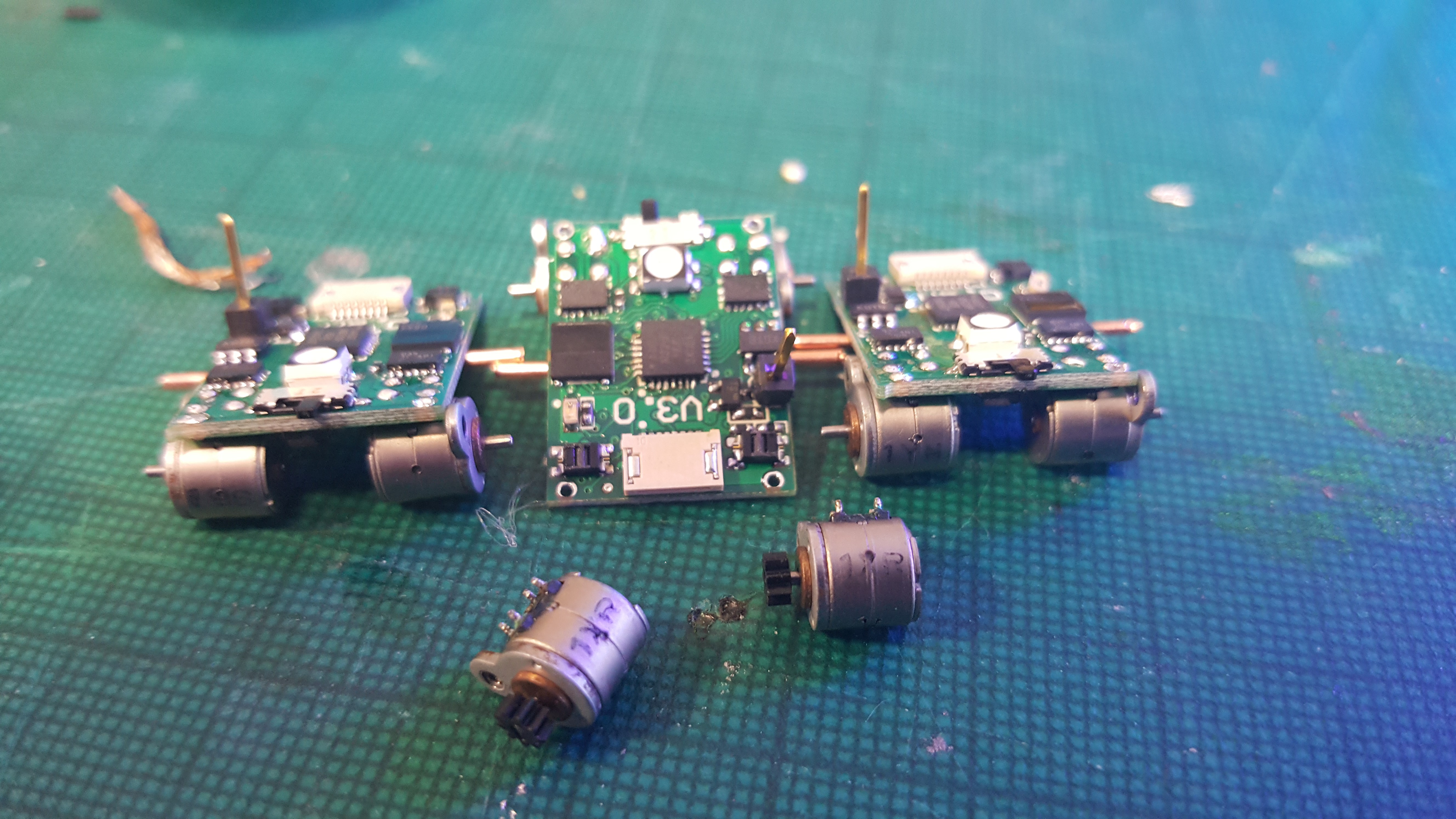
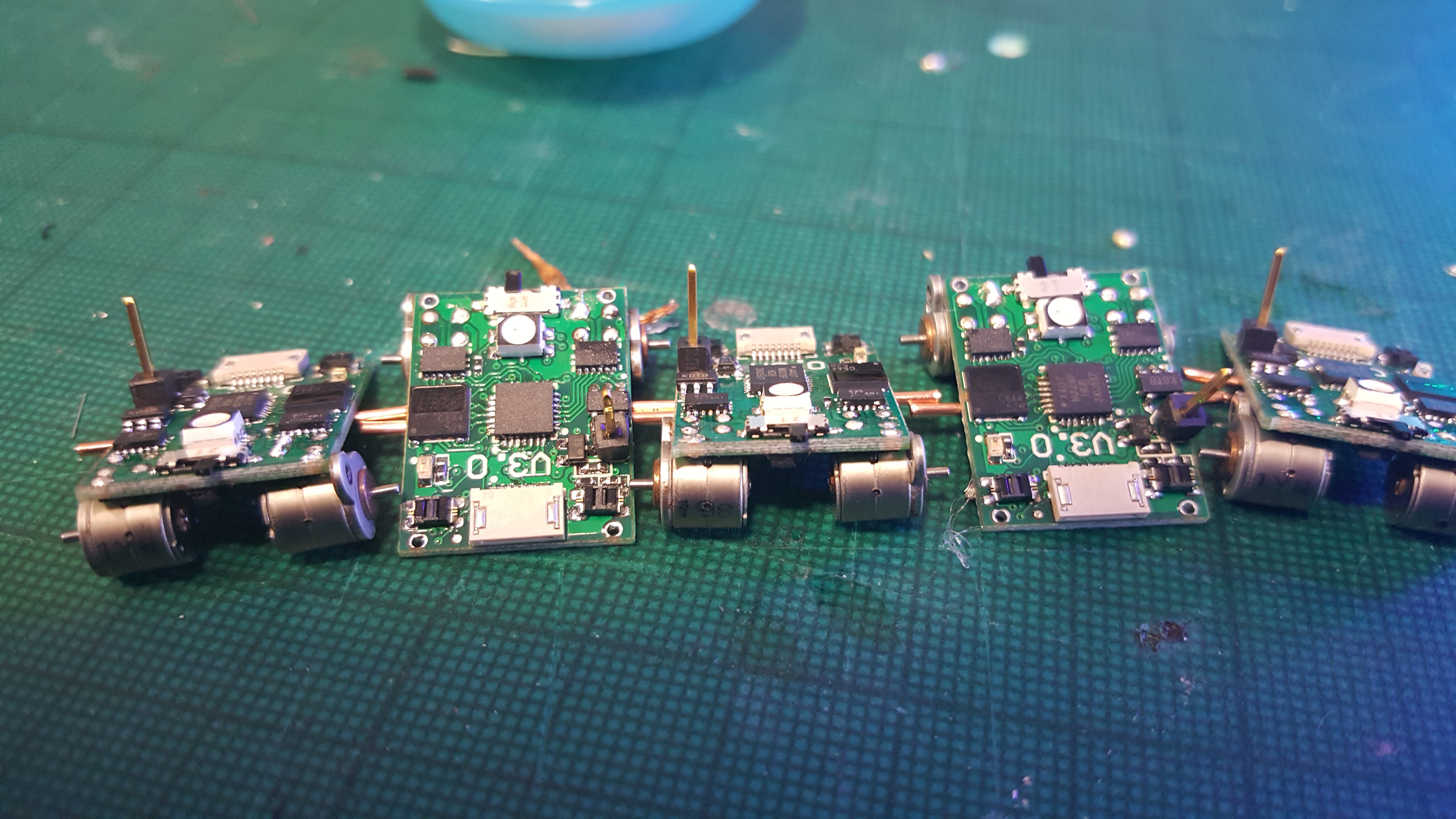
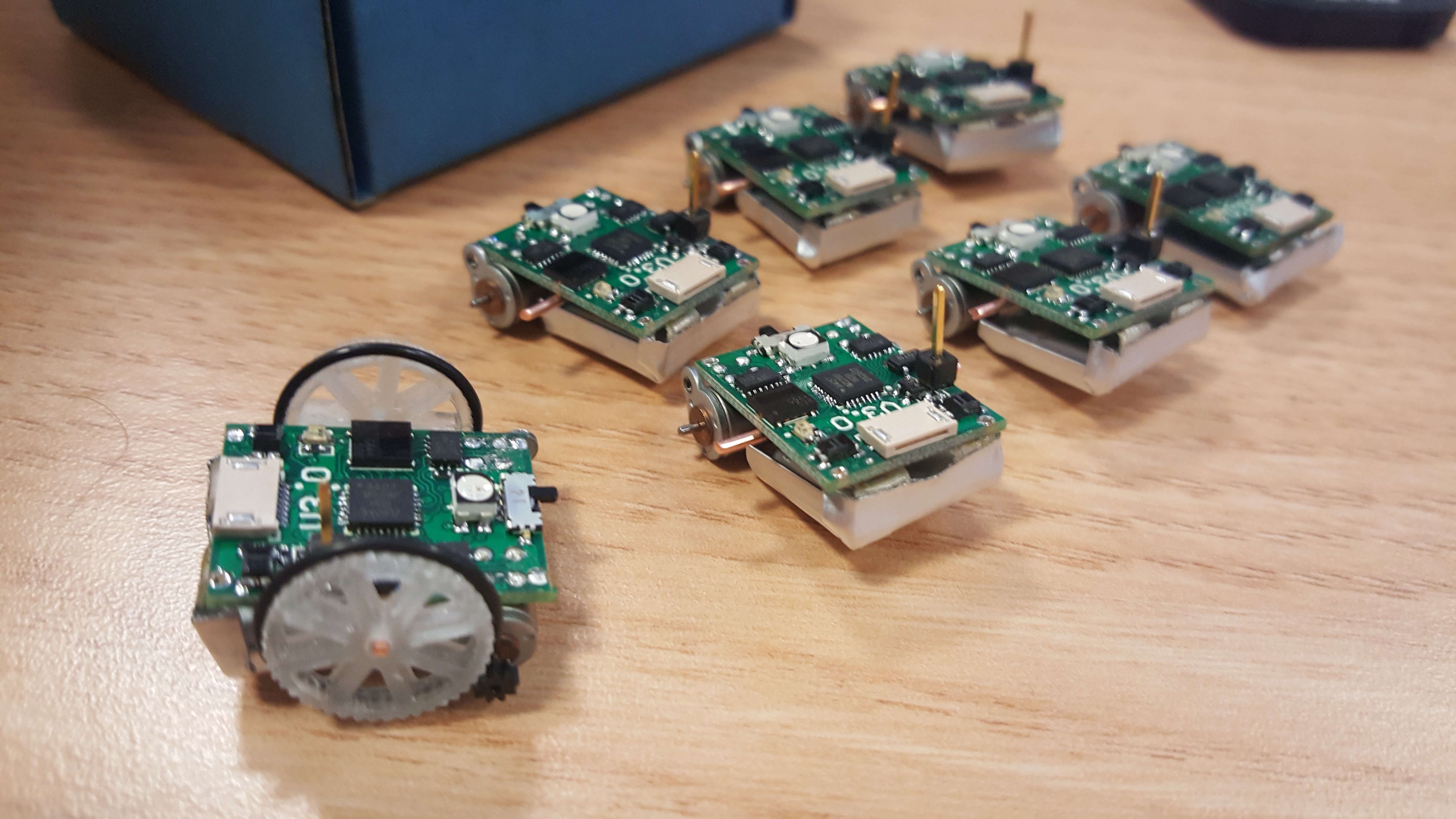
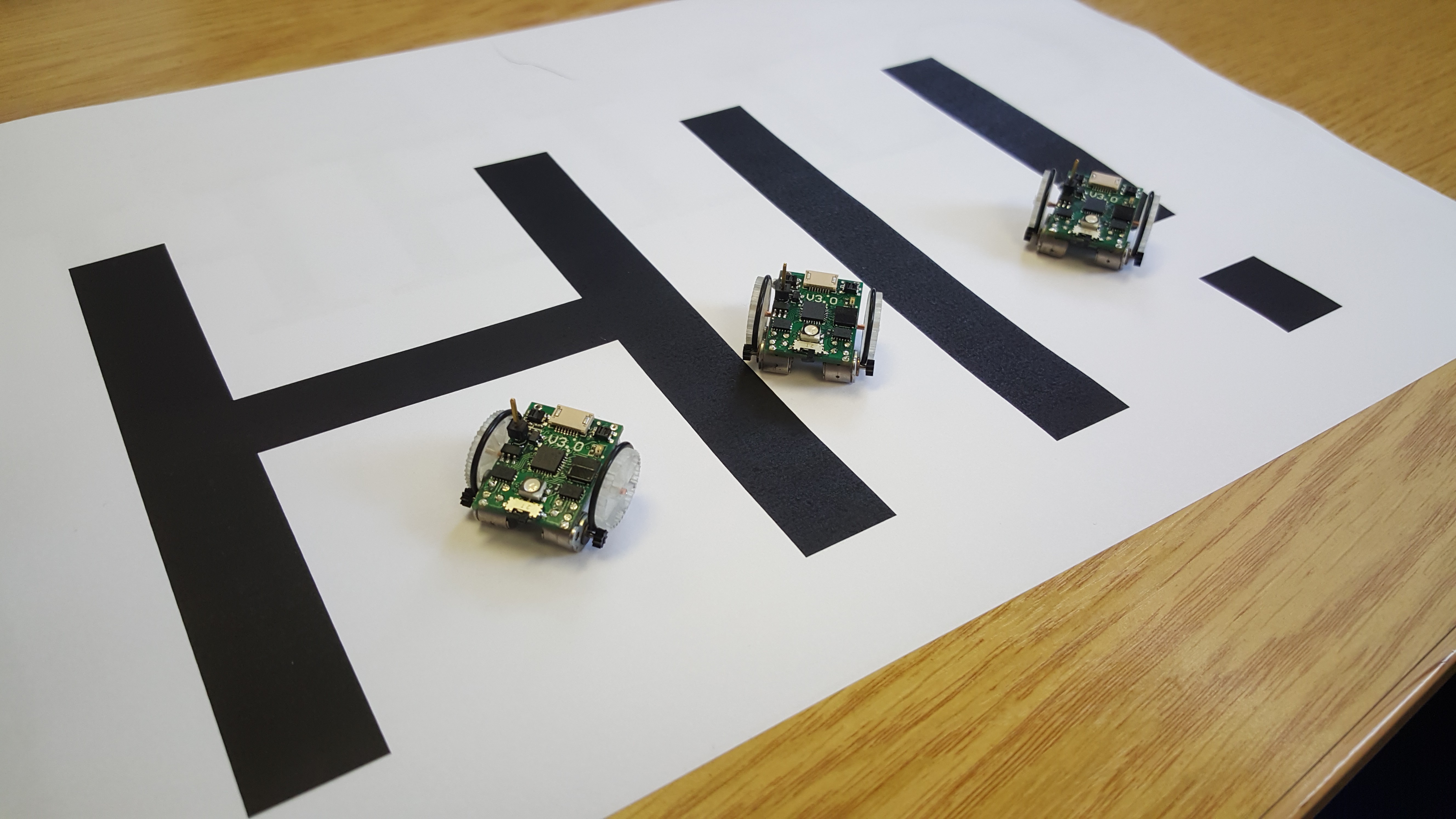
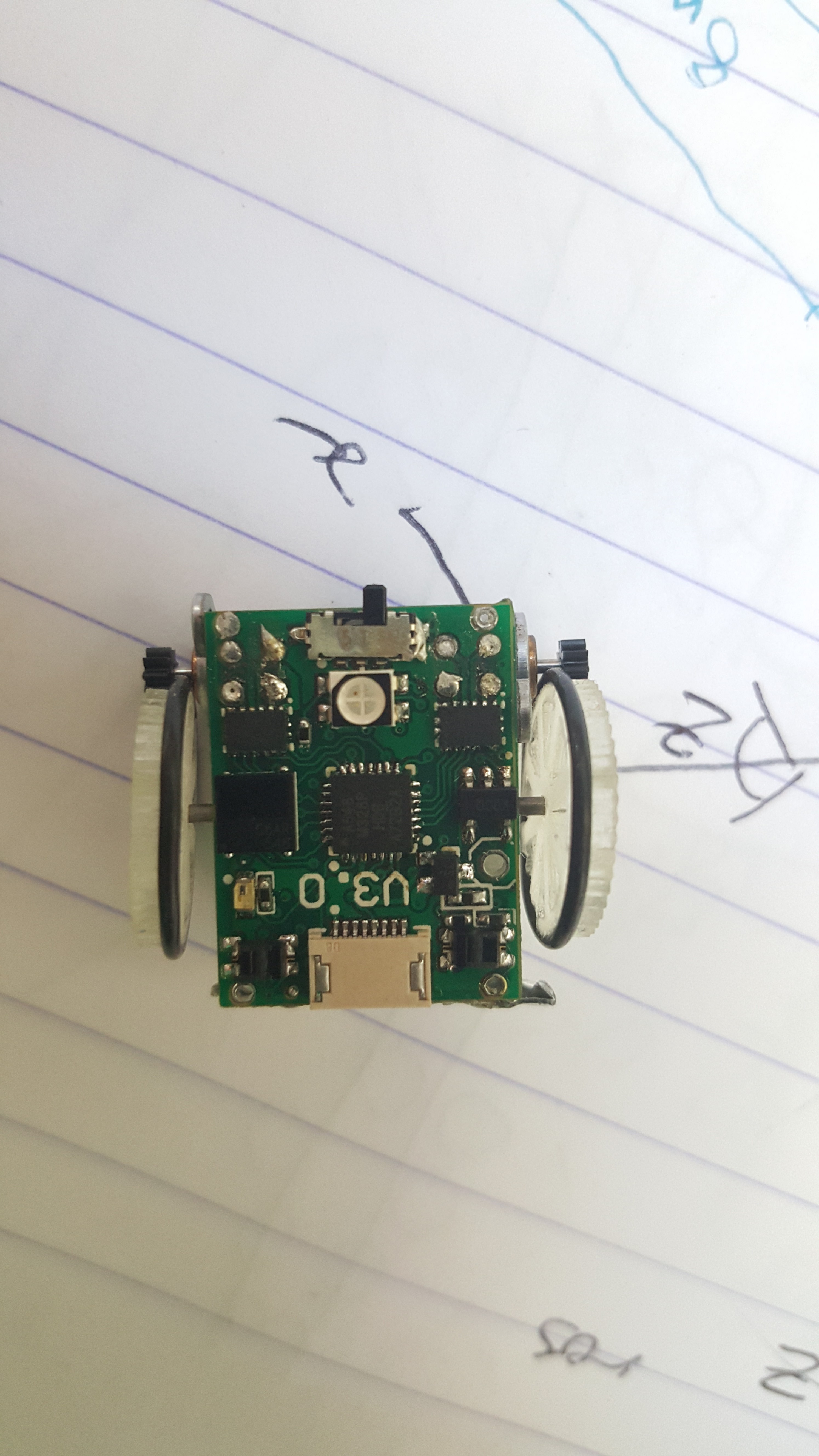
One of the things that people asked about most with our old version of the robot is: "How do you charge it?", "It would be cool if they could connect themselves to the charger." With these comments in mind we added special 'on the fly' charging capabilities to V3.0 on top of a more typical connector for charging. This takes the form of the upright single header and metallic sliding points in contact with the floor. (Many people mistook the upright pin as an antenna it seems). Till now we had not bothered finishing off the robots properly so that this feature works, so here is a run down of what to do to enable on the fly charging.
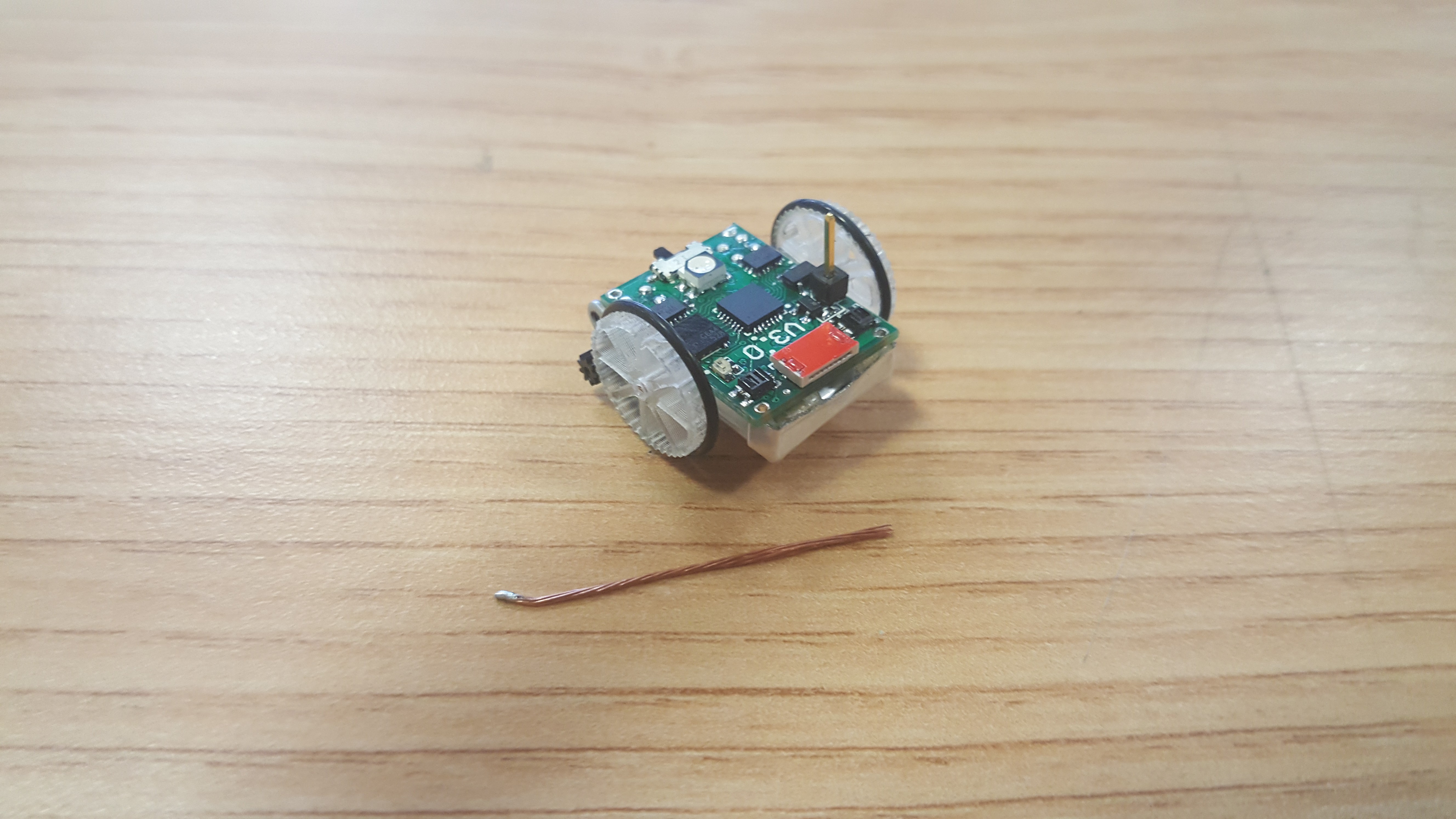
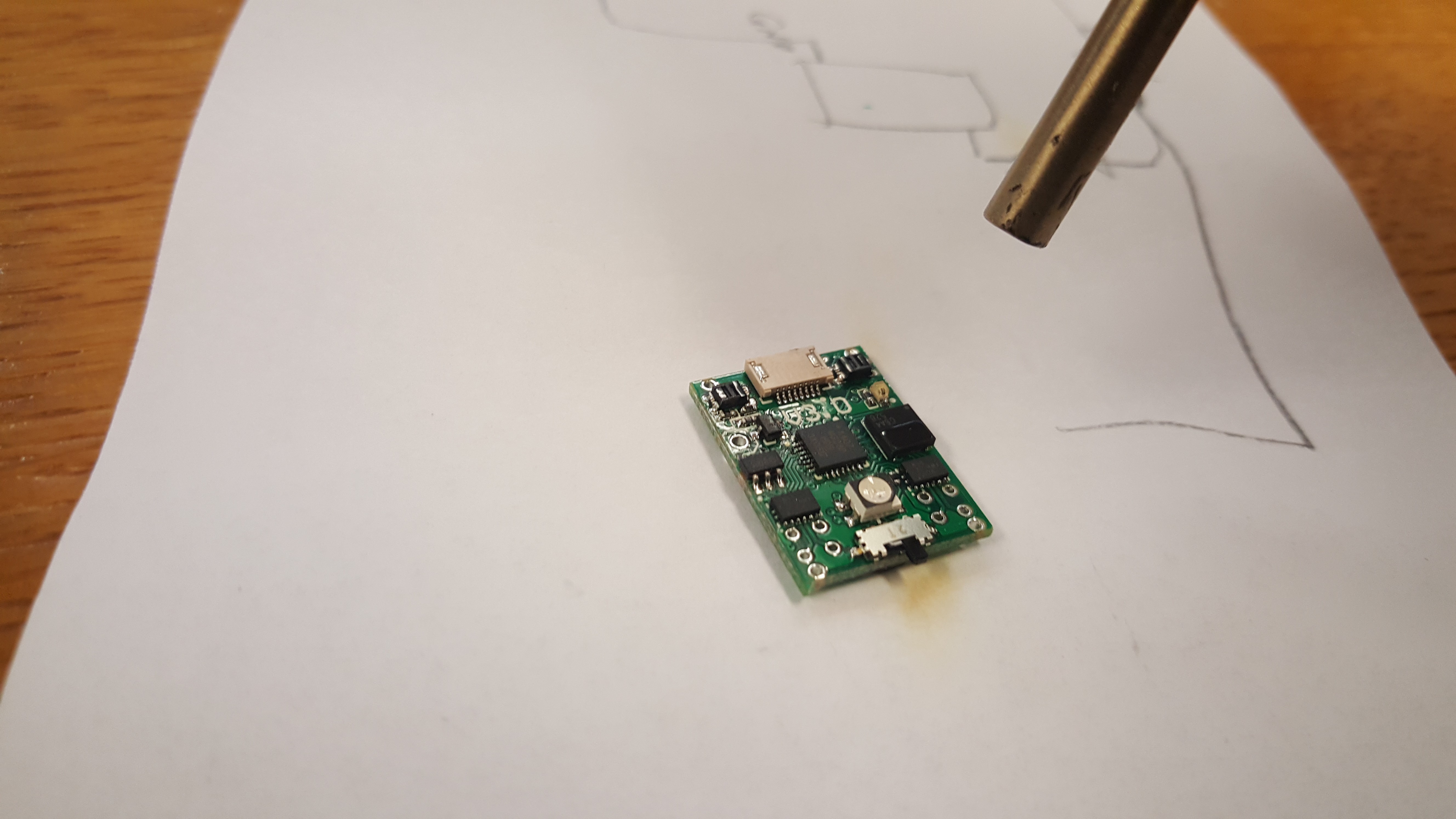
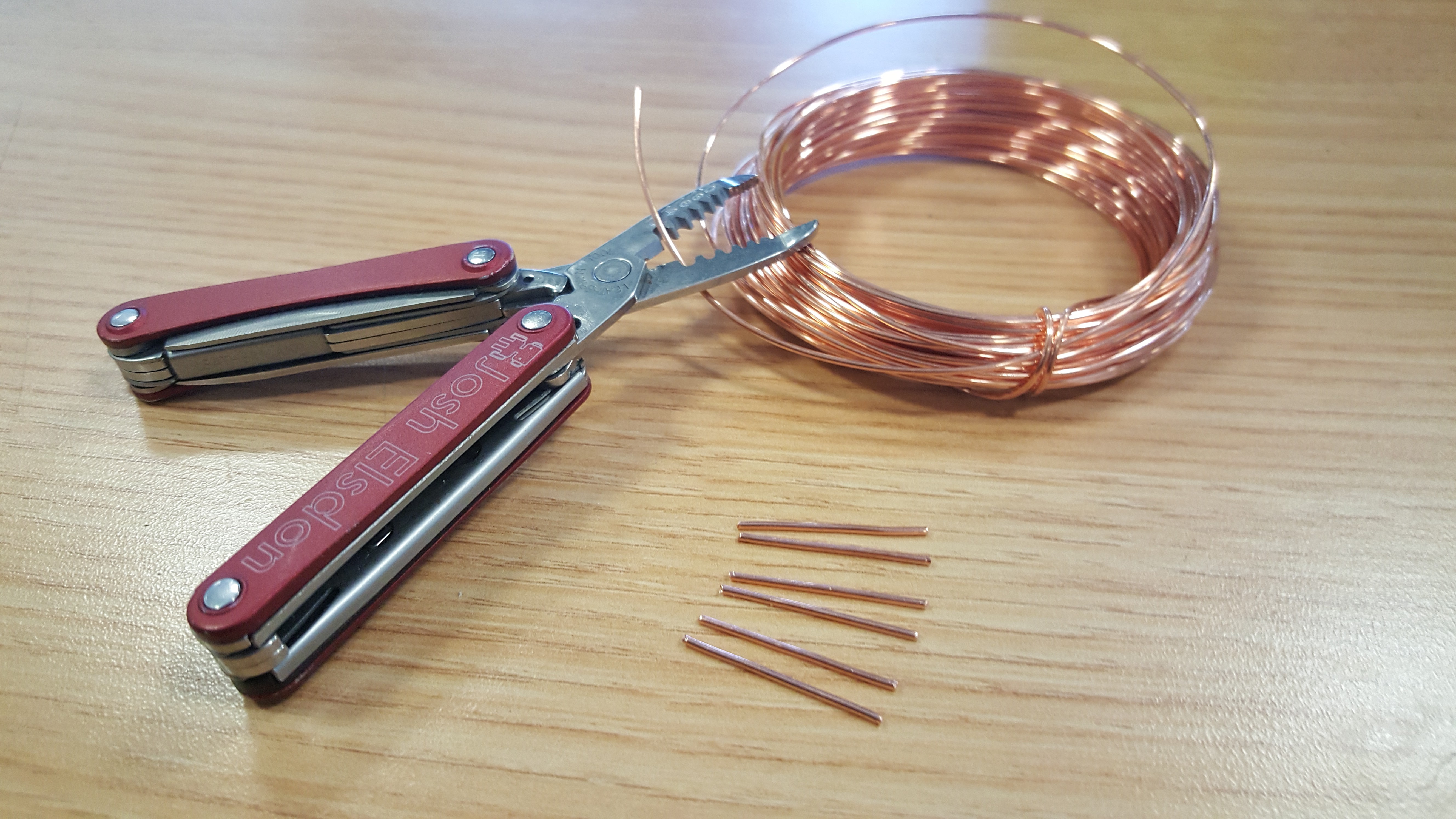
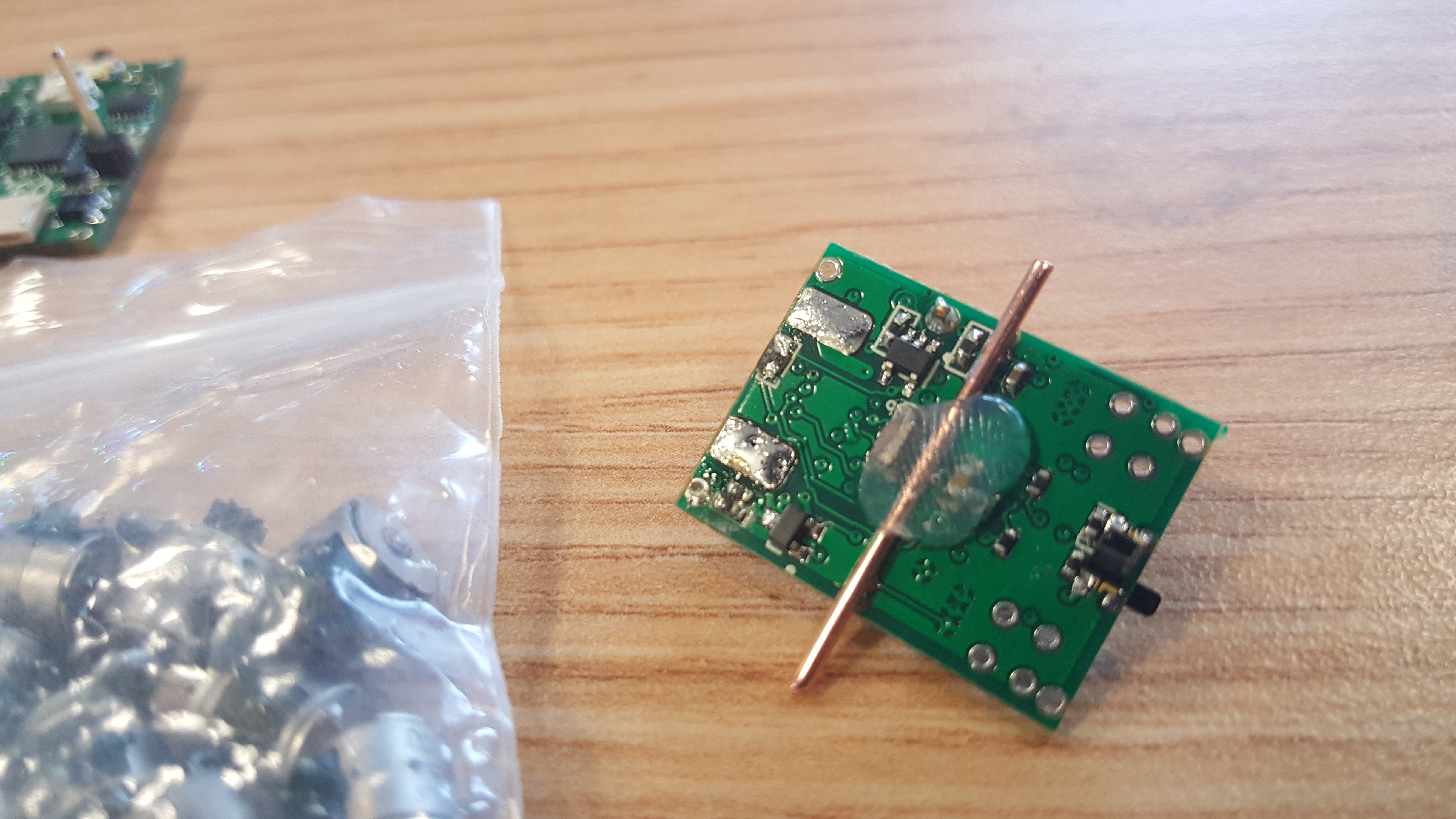
First cut around 3cm of wire, tin a short amount on one end then remove the sleeving. You should then solder the tinned end into one of the grounded vias at the front of the robot (on the connector end).
![]()
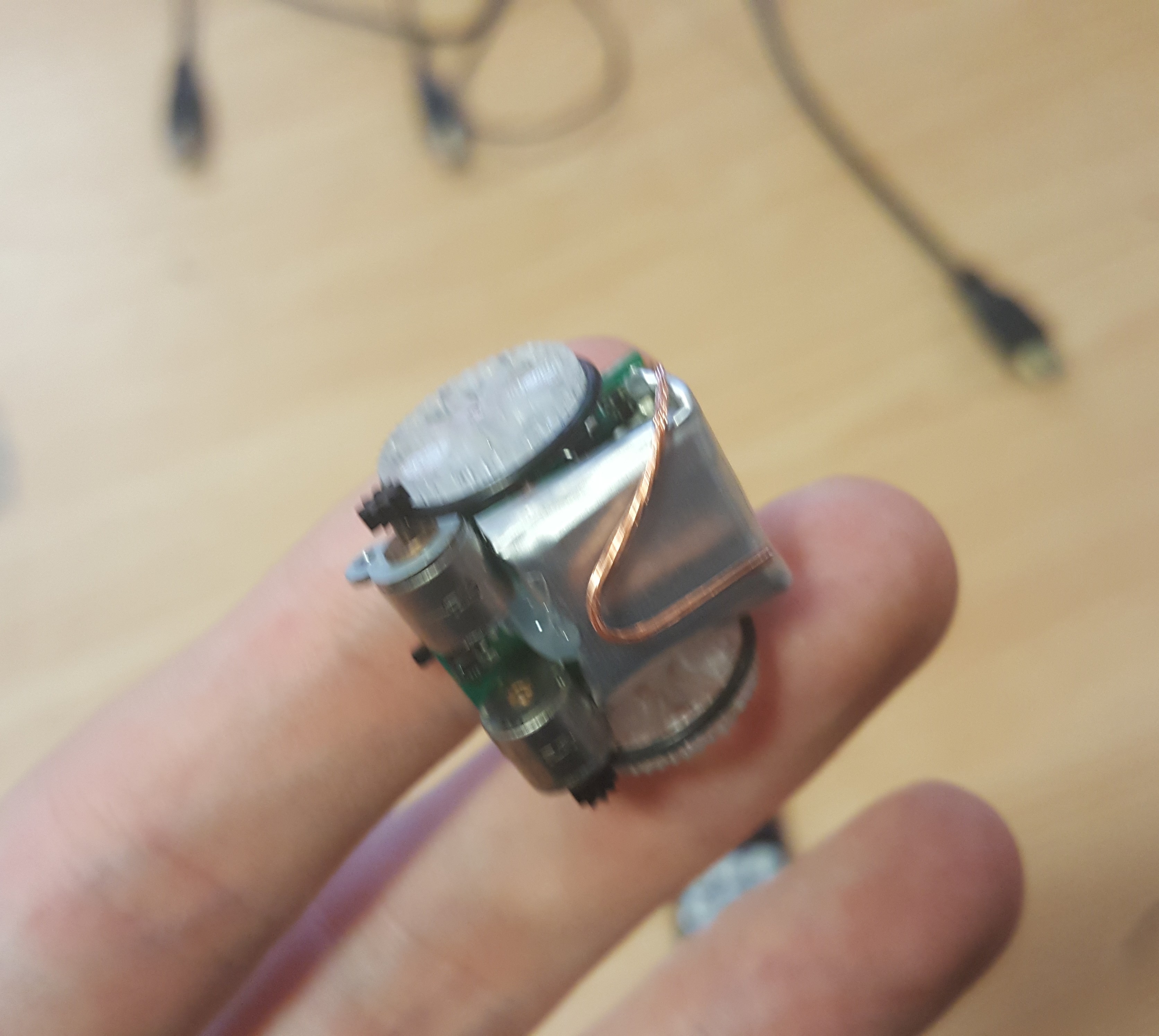
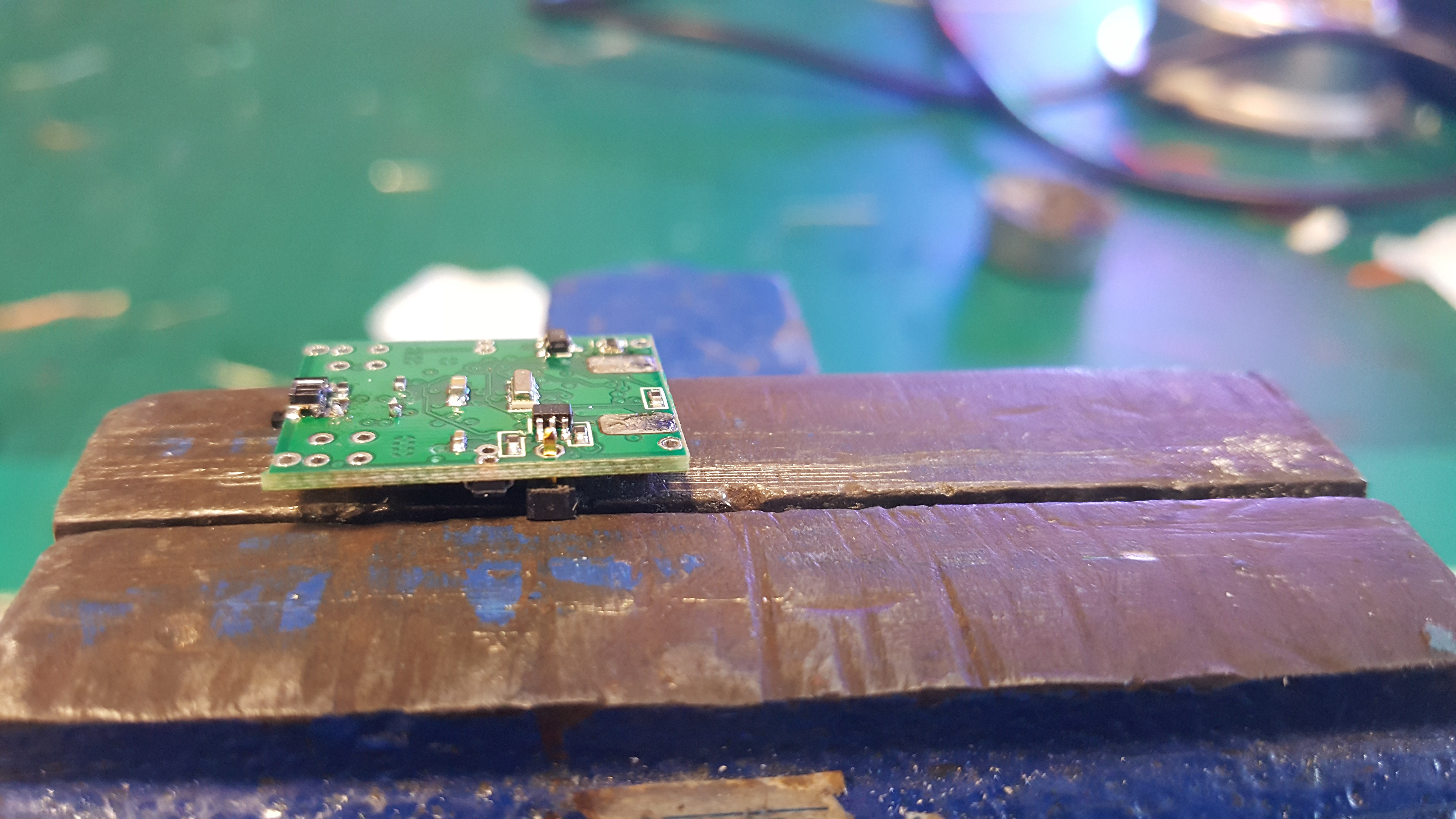
Bend the end of the wire around in a loop under the battery, we want to make sure there is plenty of wire surface area available for the copper tape. Fraying the wire probably is best here, I did not think about that at the time, it will lessen the bump under the tape and give more area for the connection.
![]()
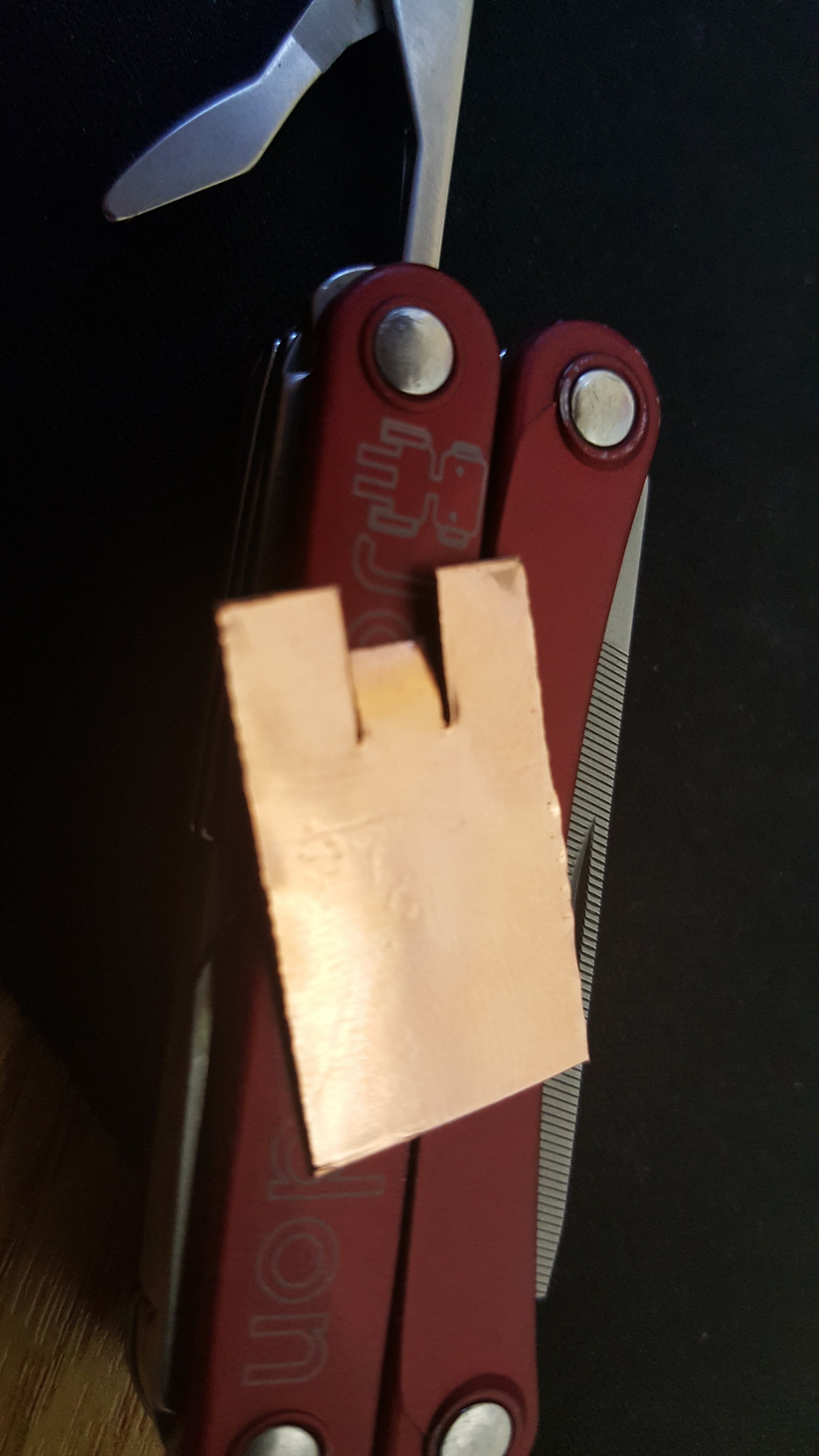
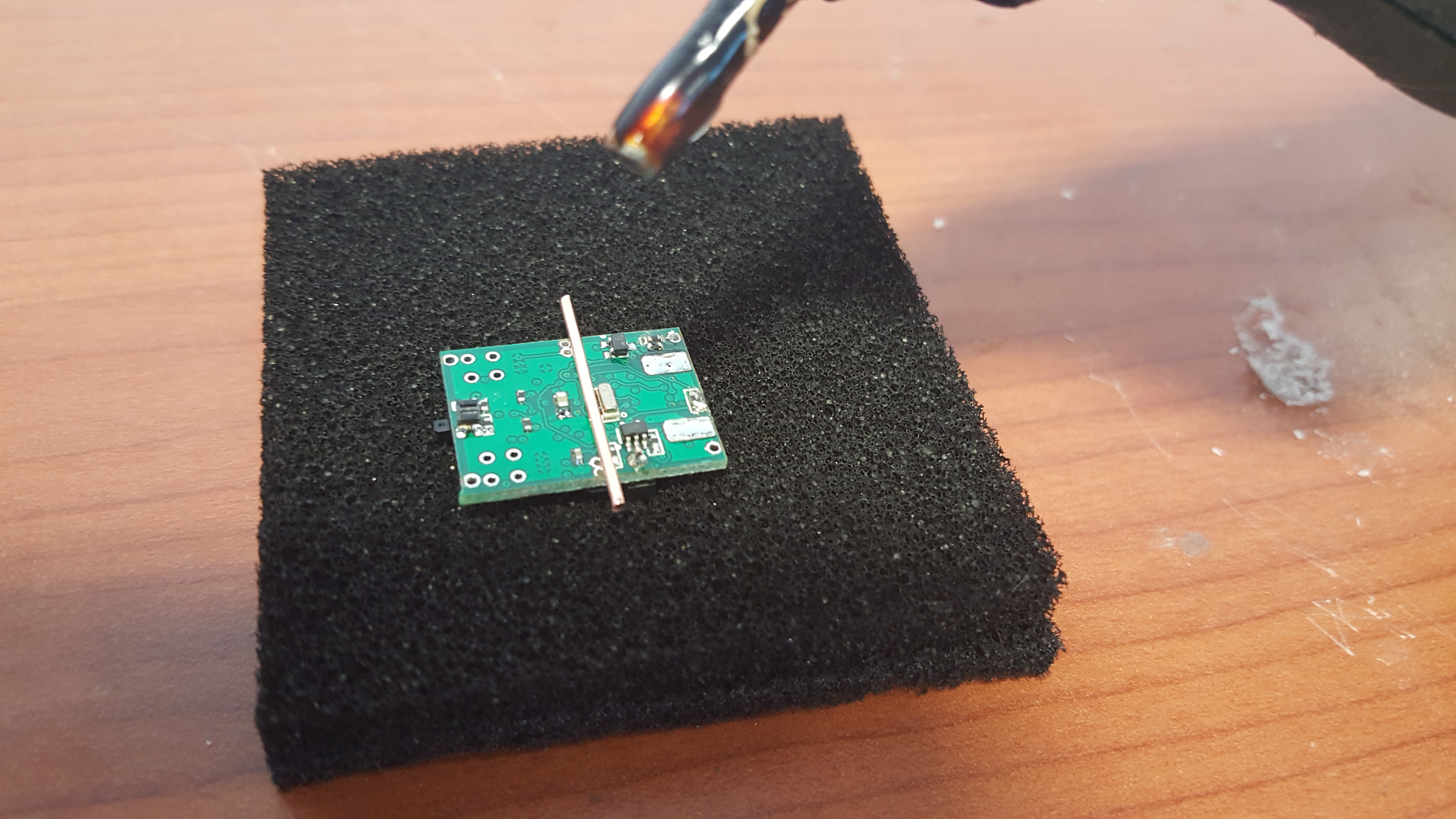
Cut a short piece of copper shielding tape, it should be the kind with conductive adhesive. I got a role that is 25mm wide, which is perfect. I cut around 15mm off. Cut two slits into the tape in one end and clip the end off the resulting 'tongue'. See below, the flap in the middle is to allow the downward facing reflectivity sensor to see the floor.
![]()
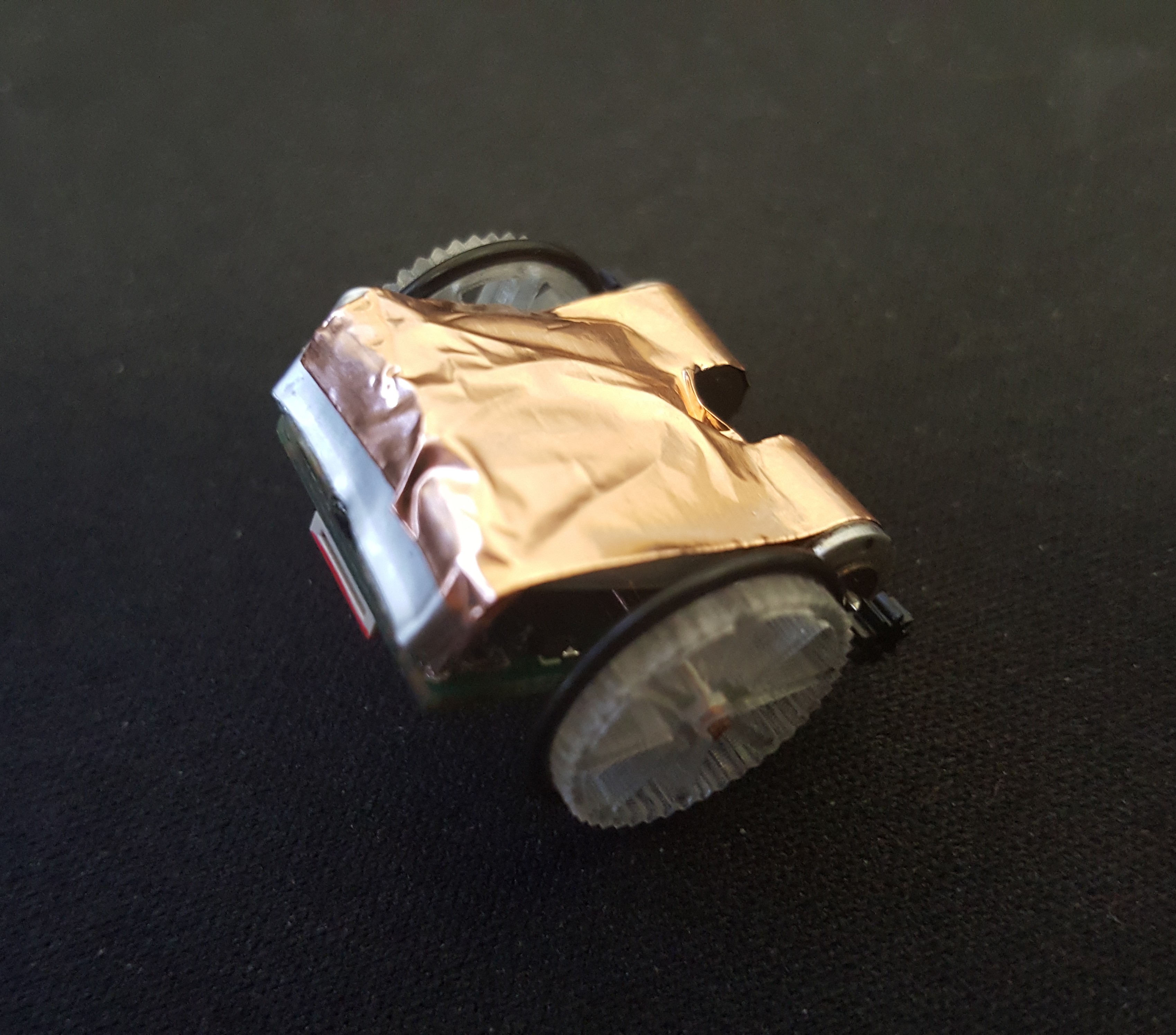
Stick the tape the the bottom of the robot. It is quite hard to do this neatly but it should not really matter. The robots slide around on their motors, so it would be good if that section is smooth and even.
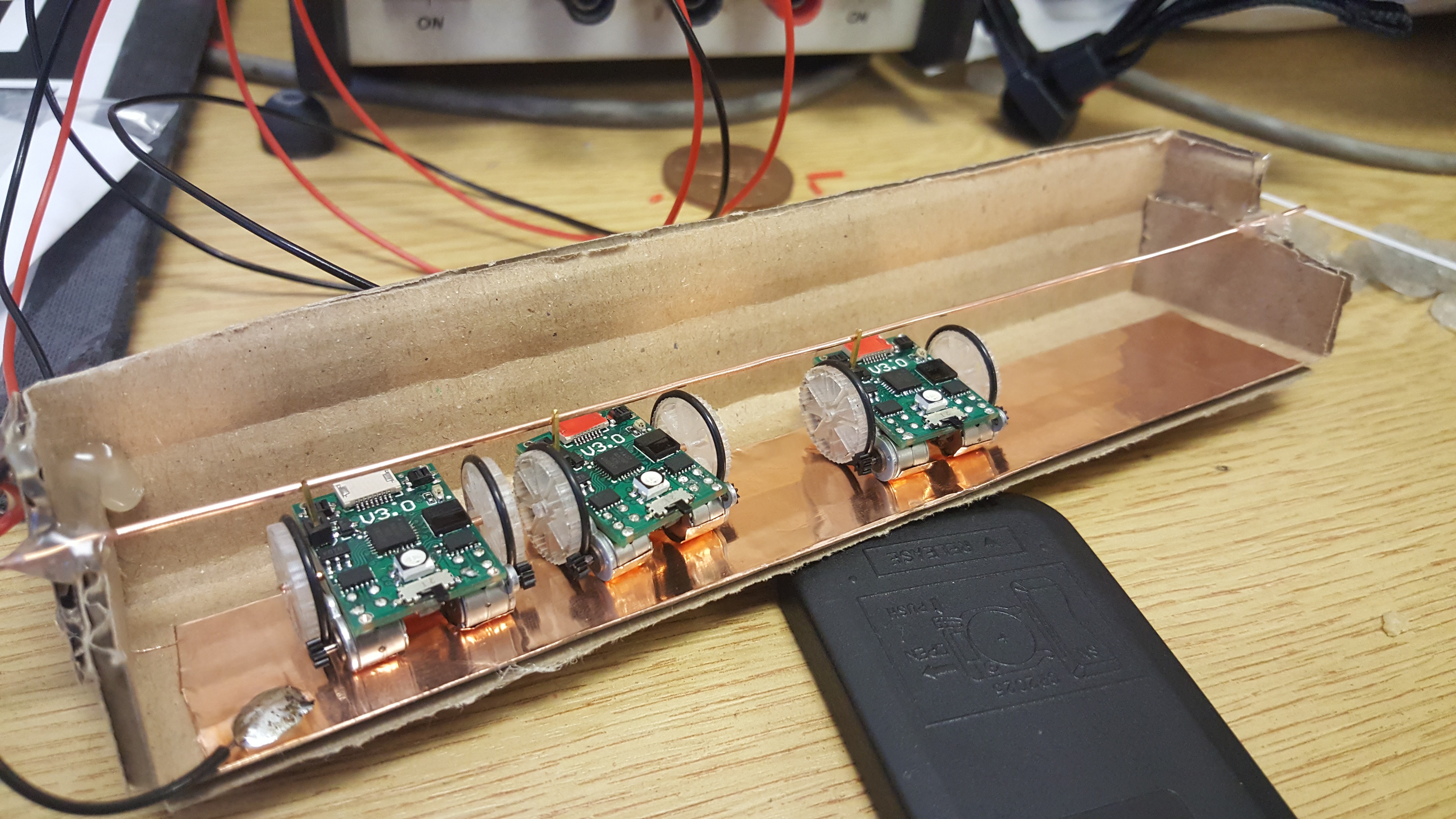
Now all you need to do is to supply 5v to the upright pin and ground the tape on the bottom. I knocked up a cardboard rig to charge multiple robots at the same time. 1mm copper wire across the top, the same copper tape on the bottom. Connect to a 5v source and BOOM! we have ourselves a very tiny refuelling station.![]()
![]()
I would not reccomend this exact lay out, as a new robot joins it depresses the copper wire, disconnection all the other robots. I am thinking that the next version will have individual overhead bars so they do not interfere with each other.
-
Arena: A mini stadium.
06/14/2016 at 18:12 • 1 commentHello, It has been a little while! Though there has been progress. We are working on getting things integrated into one complete system. The problem is that you can only awkwardly wedge a PiCam against things on your desk for so long before you feel the need to give up with frustration. This is why we need ourselves a purpose built arena!
Features that we want: Well defined arena colour; High quality lighting; IR comms from all directions; Mini-Jumbotron screen (ie. a screen). For the arena colour we are going for white to leave the colour spectrum free for game items, also we wanted to have little/no specular reflections to mess up the computer vision. To meet both these goals we chose white craft foam (EVA), soft and reflection free, if not as white as we had hoped.
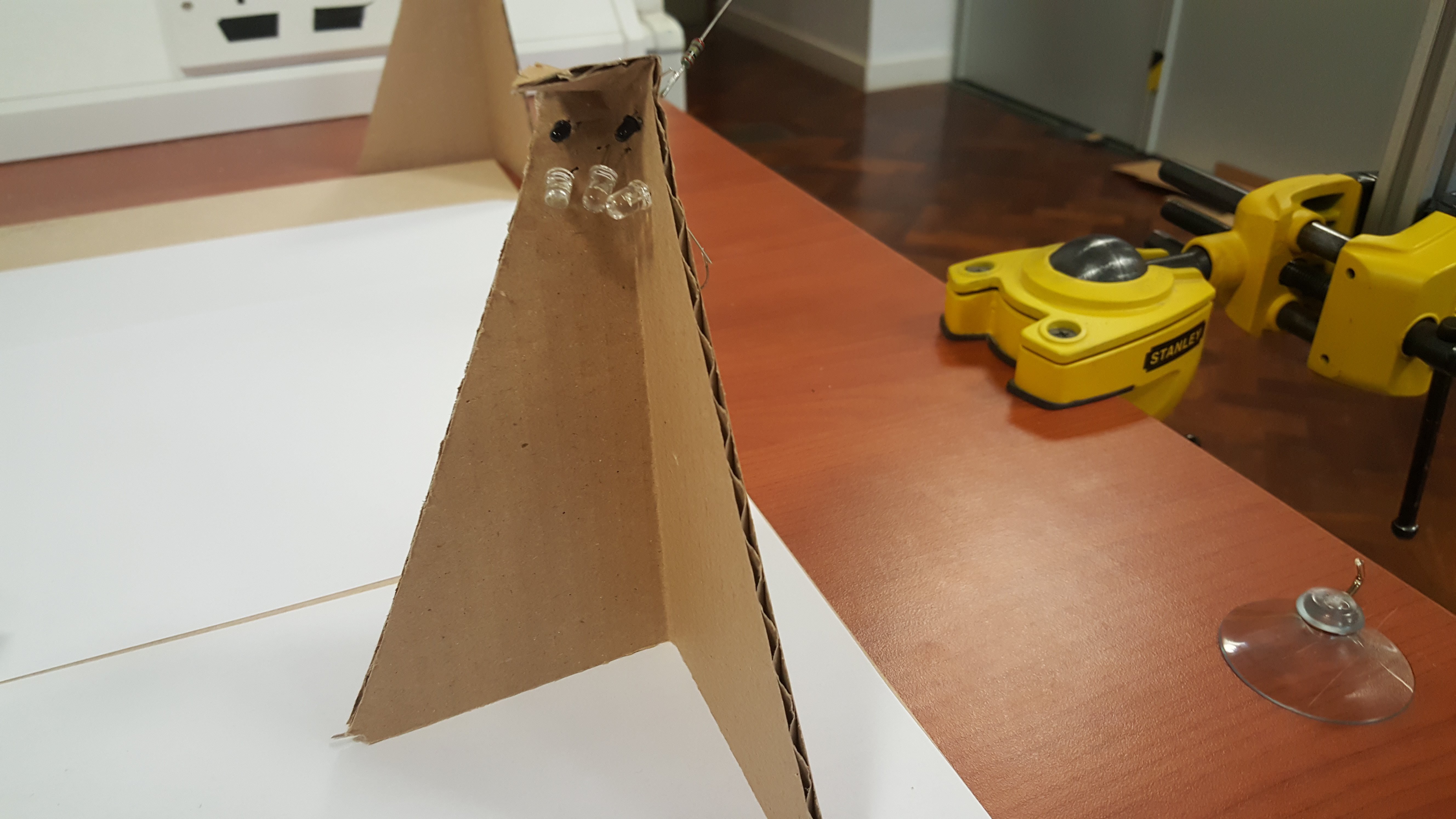
The lighting and Comms both need to surround the arena, both could be blocked by invading hands, so we need some redundancy, also lighting from the top could lead to specular reflections ruining our CV markers.
![]()
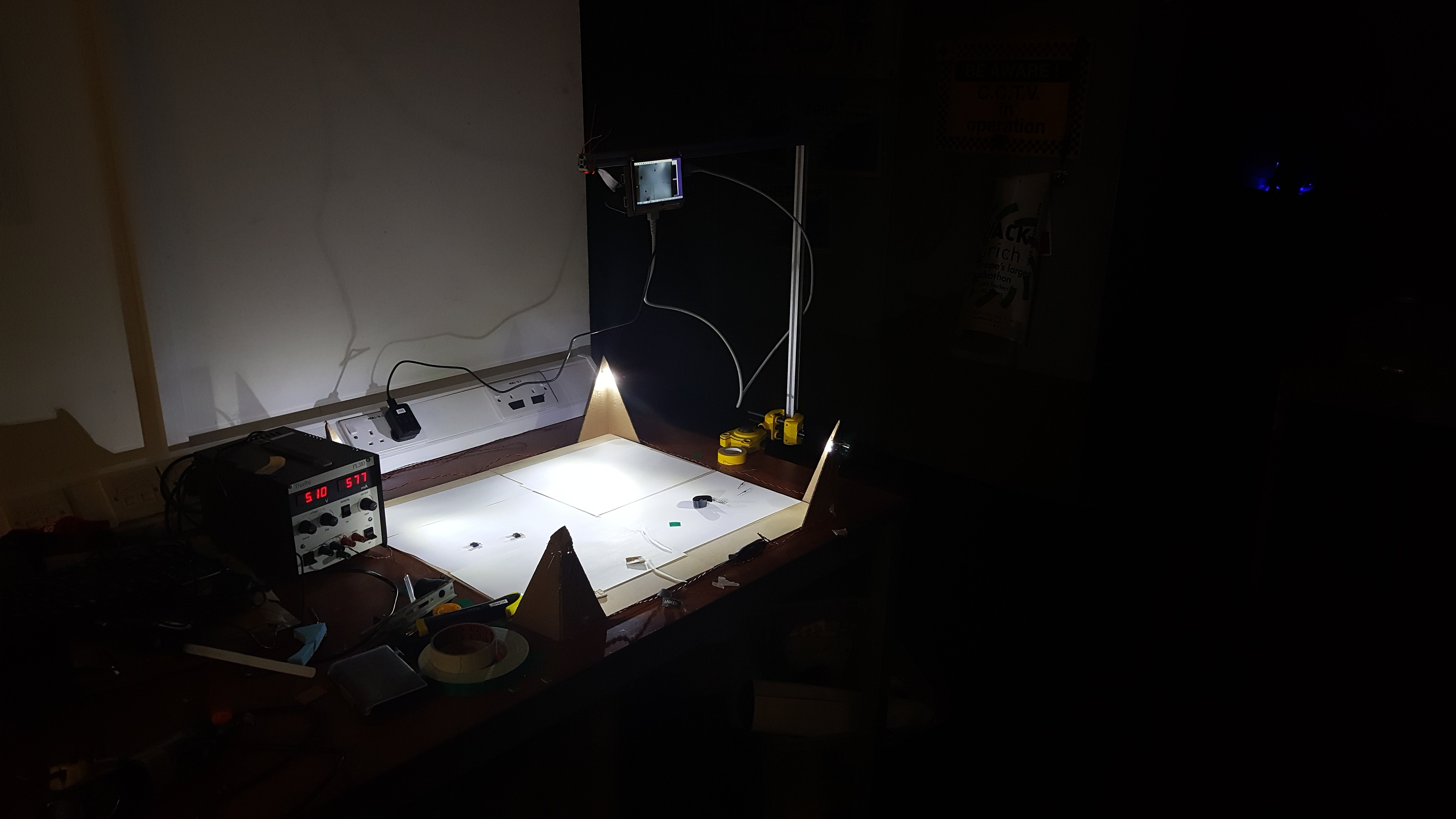
Cheap cardboard towers for now. For the Mini-Jumbotron I am using an adafruit screen I had left over from a previous project. The screen, Pi and camera are suspended from a aluminium extrusion based gantry, that is clamped to the table using a vice.
![]()
Here is an image with the lights off, you can see that the lighting is holding its own. The screen will be used for configuring the experiment on the fly, it is touch screen, which makes quite a natural interface for identifying game objects.
![]()
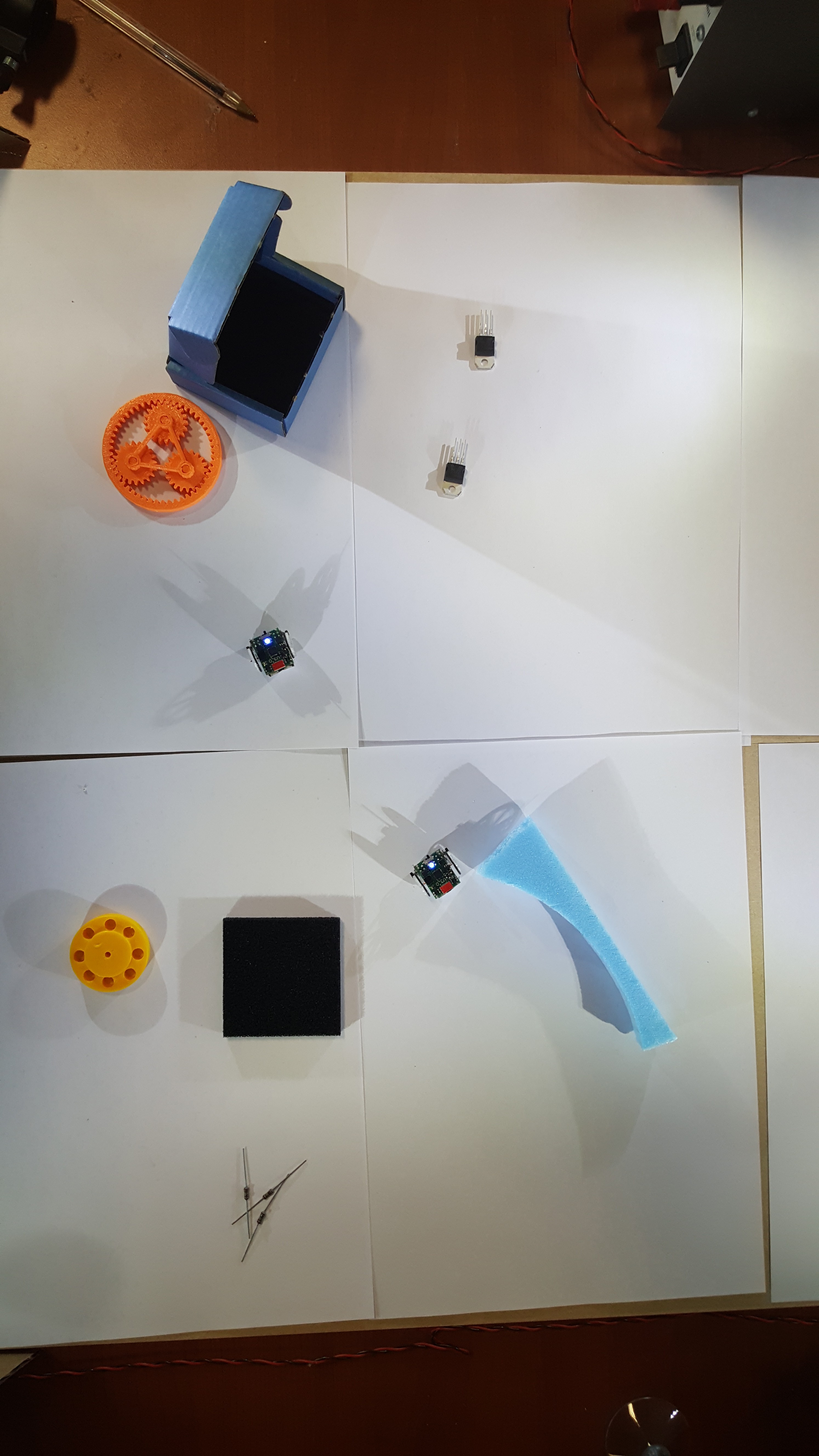
This is the kind of image we can get from a camera (in this case a phone camera, as the Pi was not running at this stage of the build). Notice that the image is bright and well defined, the shadows are a little annoying, but they can be excluded easily in the computer vision algorithm.
This setup doubles as a pretty snazzy mini photo studio.
![]()
Not bad eh?
Lets have the robots explore their new home a little.
Over and out, see you all soon.
-
ROS Integration : Finding the Robot Transforms: Part 2
05/30/2016 at 14:14 • 0 commentsYesterday I showed the computer vision part in isolation, today we have the ROS system doing nearly everything that it needs to do. Joypad -> desktop -> arduino interface -> tiny robot -> Camera -> extract robot positions -> broadcast transforms to ROS.
The communication between the arduino and the robots is still pretty naive, but all the parts are there for full linear/angular velocity control at around 300 Hz shared between the robots (so 30Hz for 10 robots). Most of the delay you can see in the video is due to the time it takes to draw the visualisations and display them, plenty of room for optimisations to remove the majority of the lag.
-
The Sources, where are they?
05/29/2016 at 21:49 • 0 commentsHello,
Up to this point the sources have been closed, not for any particular reason, mainly laziness. Now that some aspects of the project are working I wish to share the sources for your perusal. Though this carries a YUGE disclaimer. I would not recommend that you implement the work as it stands, there are many bugs and design changes that are in the works. We are still acting (very) actively on this project and we have the materials at hand. We intend to do a proper release later, with documentation, build instructions etc at a later date. Consider this a (pre) alpha release, and stay tuned for updates.
PCB source. Shared under Attribution-ShareAlike 4.0 International (CC BY-SA 4.0) .
Software source. Shared under GNU General Public License V3.0 .
-
ROS Integration : Finding the Robot Transforms.
05/29/2016 at 18:53 • 0 commentsHello,
So progress is quick recently! Last time we saw the robots moving under control from ROS, so the next problem for a proper closed loop system is how do you know your location. The robots do have odometry on them in the form of stepper motors, if we know how many steps each motor and in what order we can calculate where we are. That is as long as there is no dust, or hair, a mild breeze or bad omens. To properly know where we are we need some absolute positioning.
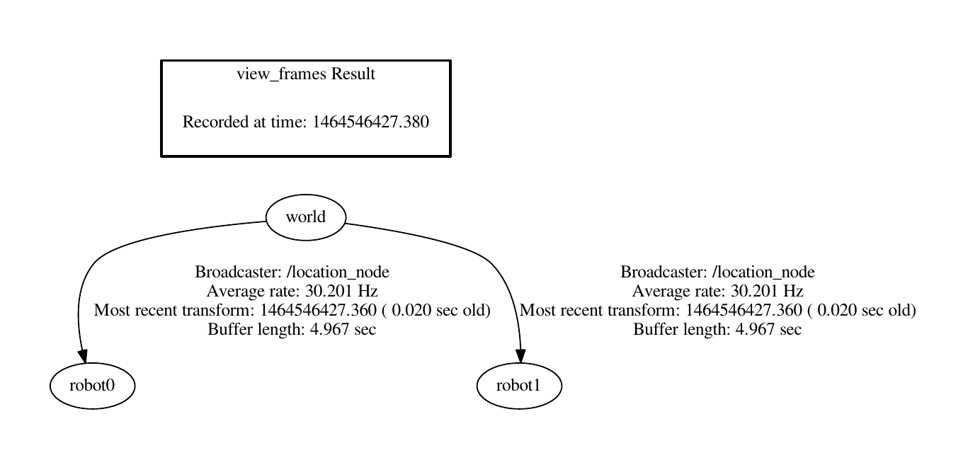
For this purpose we are developing a Computer Vision (CV) system to find the robots, calculate their position and rotation and publish this onto the TF tree, which is ROS's need little bag of tricks for keeping track of everything. We are using TF rather than a standard topic because TF does nice things like buffering past transforms, this way you can see where things were at a critical time in the past. Where were the robots last time I sent them a movement command? Easy peasy. Controlling robots well that are this fast (5g can get going quickly) we need to be very careful about latency and correcting for it.
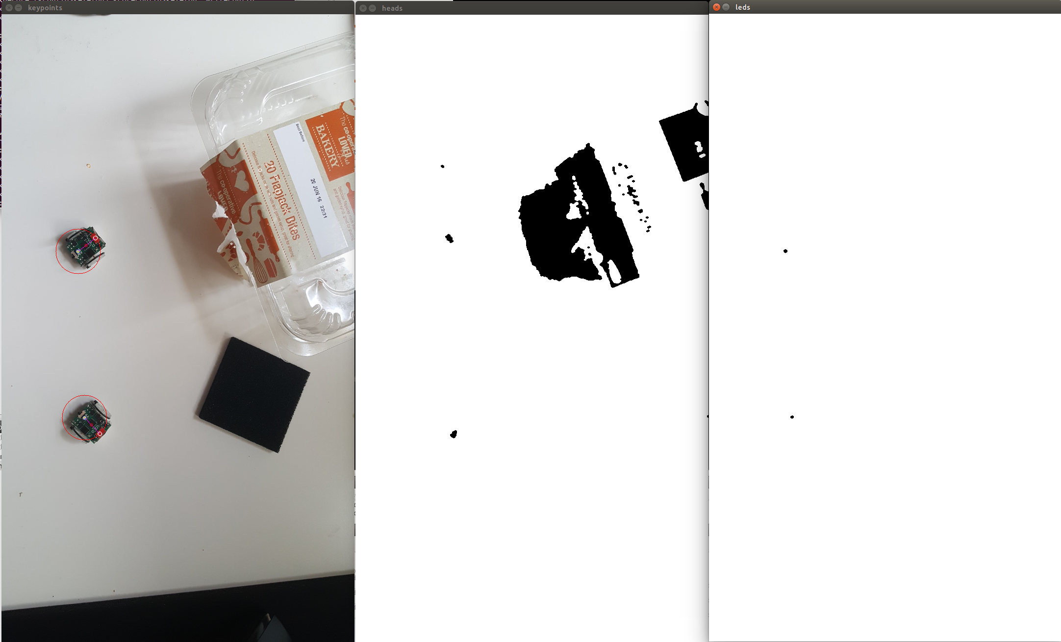
So alas how are we finding the robots visually in a potentially noisy environment? There is an on board led, which we can set to any colour we want, in this case blue. Also the connector has been painted with red nail varnish. Using these 2 points we can find the location and heading of the robot. To separate out these features simple colour segmentation has been implemented, giving us many blobs of 'Red' and 'Blue'. We know how far away from the ground the camera is, so we can know how many pixels should be separating the LED and the painted connector, we can also filter the blobs by how large they are. So using the LED blobs as a reference we find the distance to all red blobs for each blue LED blob, we then select the one that is closest to the correct value, tossing away any LED's that don't have a good match. Then, fingers crossed, we have found all of the robots. Here is a demonstration, LED's on the right, red 'front connector' blobs in the middle, and the result on the left. The red circle indicates the radius that was searched for (red blobs on that circle will score highly). There is also a thin red line indicating the heading of the robots, and a red dot indicating the centre of rotation. The cakes are empty, because I like cake.
![]()
A little bit of vector algebra later and we have the position in the frame and the rotation relative to the x axis. This can then be published to TF!
![]()
-
ROS Integration.
05/28/2016 at 18:19 • 0 commentsHello,
This is a short update: ROS is go!
To come: more sophisticated communication allowing more flexible movement (it is mostly there).
-
System Architecture: Top to bottom.
05/25/2016 at 15:20 • 0 commentsThe robots are in a mostly functioning state with respect to their hardware, we will discuss the up and coming 4th version of the robots soon. This post is about what software we are going to produce and how it will enable people to do some very cool things (and make it possible to make interfaces for educational purposes).
Our aim is to integrate these robots with ROS , which is a huge set of libraries, communication tools, and algorithm implementations that is used heavily in the world of research robotics. It is quickly becoming the dominant interface for software intended to control robots. The cool thing about ROS is that as long as the software interfaces with a new robot are defined correctly, all the the work by the leading researchers around the world can be directly applied to your new system. Think about all of those efficient route planning algorithms, SLAM frameworks, stochastic decision making etc that your project can use with minimum work. The point is, ROS is awesome, we want to use ROS, you should want to use ROS.
So job done right? 1. Install ROS 2.???????? 3. PROFIT$$$. Unfortunately things are not that easy for us. ROS is a system generally designed for 'desktop' environments, x86 and ARM are supported, but the tiny processors on our robots are not. There is a module available called RosBridge that is for the purpose of interfacing with awkward end nodes, whether they be arduino or a webpage, and this communicates using a JSON (read: lots of text strings). Therein lies our problem, we have almost no communication bandwidth. Our IR interface can send around 2000bits per second if we push all of the timings up to and a little beyond what the data sheets recommend. To make things worse this is the only channel for all of the robots in the system, so if we have 10 robots they get only 200 bits per second. There are a few other reasons why the RosBridge direction won't work, but I think that the above is convincing enough.
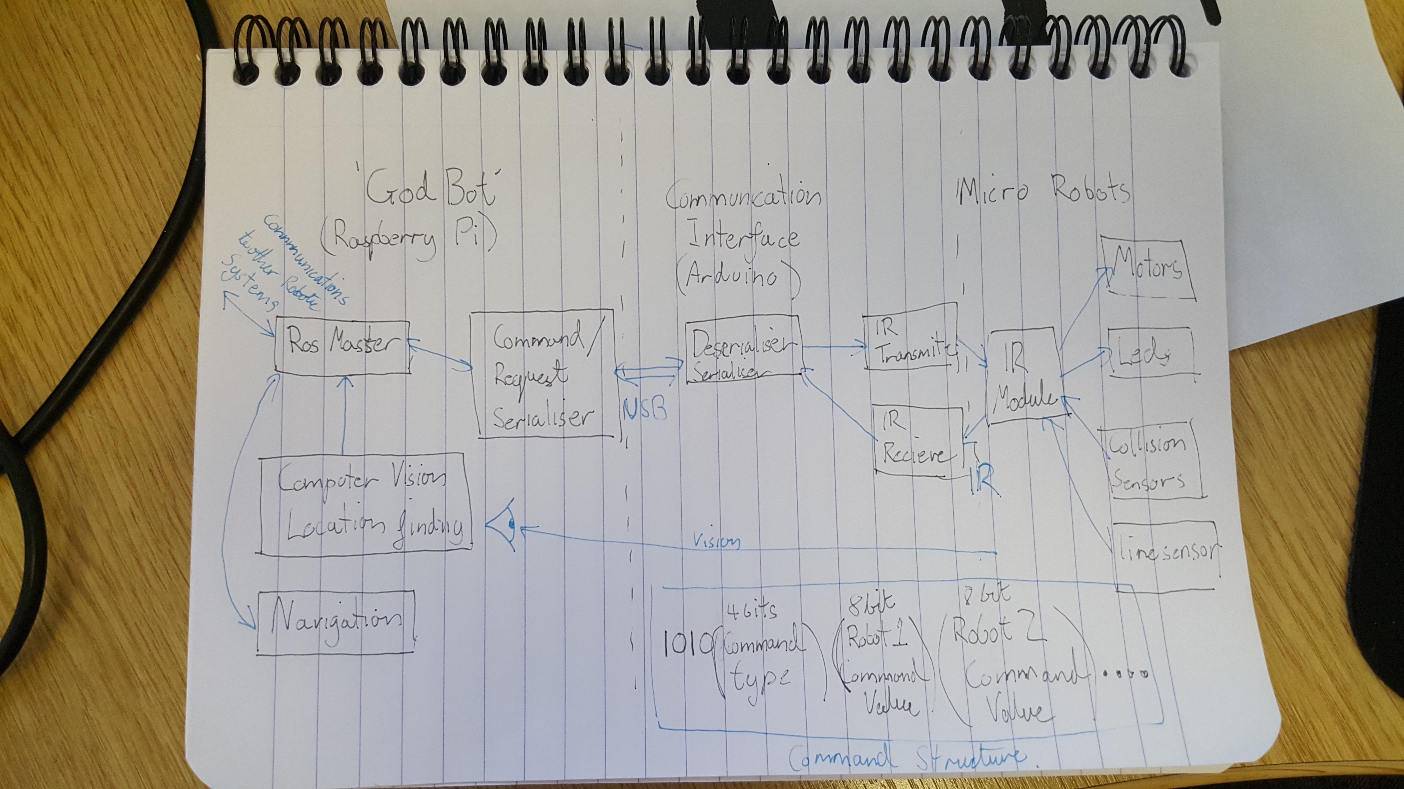
So our plan is to integrate ROS one level higher in our system, on a raspberry pi that we call 'GodBot'. GodBot's job is to do all high level tasks, calculating trajectories, interfacing with other ROS enabled robots etc. All movement commands and sensor update request will be transmitted down a serial link to an embedded system that will handle the sequencing of the IR, at this time this is done by an Ardiuno. The data packets will then be sent out to the robots using a dedicated time slice to each robot. We will use a very short synchronisation symbol (4 bits) to keep things on track. Sensor requests will be handled similarly, each robot given its allocated time to transmit on the channel. Below is an outline of how the data flows around the system.
![]()
This system does require a little bit of snazzy initialisation, every part of the communication needs to know how many robots there are, and each robot needs to know what number it is. That will be a topic for a future discussion, good news though, it should be fully automatic!
-
Robot construction, a bunch of 6: Part 2.
05/19/2016 at 11:27 • 5 commentsHello,
The last part went (rather quickly, see here for a longer version) over the soldering procedure for the SMD parts. Here I will present some of the steps to finish the robots.
You may have notice that there was a component missing from the previous log, due to a shipping error it was not in the right place at the right time. Here I am placing it, the black square IR reciever (about the same size as the main chip), on top of the solder blobs that were left from the reflow process. Heat it gently at 300c with a hot air gun and it should connect to the pads with springy surface tension. I strongly recommend a 'proper' hot air rework gun, the over powered hair dryer kind will melt all the solder on the board, probably making a mess of things.
![]()
Making shafts is as easy as cutting short pieces of 1mm copper wire. Before I was using piano wire, but that stuff is hard and will ruin wire cutters (if you look carfuly you can see the scar on this set). Try and get the wire as bend free as possible. The length depends on how exactly you made your wheels. Mine came to 24mm.
![]()
Next is soldering on the single pin header for the 'on the go' charging circuit. It is surprisingly difficult to do well as everything is so hot and small! I ended up wedging the header in a clamp and placing the board on top. Make the joint, then re-melt the joint whilst aligning it to make the header point directly 'up'.
![]()
I used hot glue to attach the shafts to the bottom of the board. We will need to 'reflow' this later to precisely line up the shafts, but aim for the middle.
![]()
The result.
![]()
Soldering on the motors is another tricky task. Ideally you should make a jig to hold them in place. I went for the 'hold everything awkwardly in place with one hand and jab with the soldering iron with the other hand' method. The motors are very fragile, and you should handle them with the utmost care.
![]()
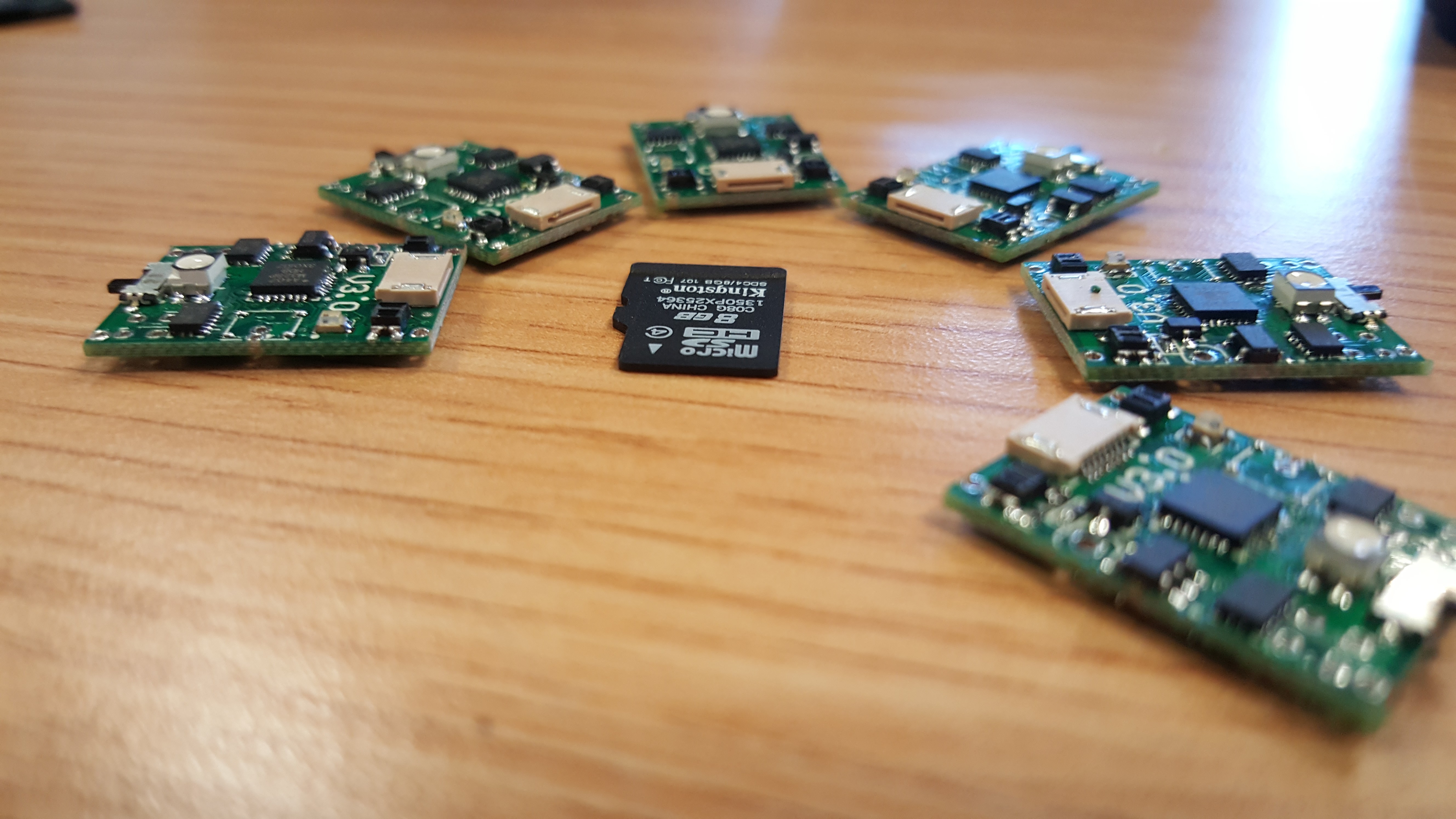
A shot of 5 robot sitting proudly with their new motors.
![]()
I forgot to take pictures of soldering the batteries. The key thing is to not make the battery short circuit. LiPo batteries do not like to be short circuited ;). The tabs need to be trimmed to size, check the pad size for reference. You will need lots of flux to get the connection to work, they use those horrid 'supposed to be spot welded' tabs, and they do not take solder well. Here is a bunch of 7 robots almost entirely finished.
![]()
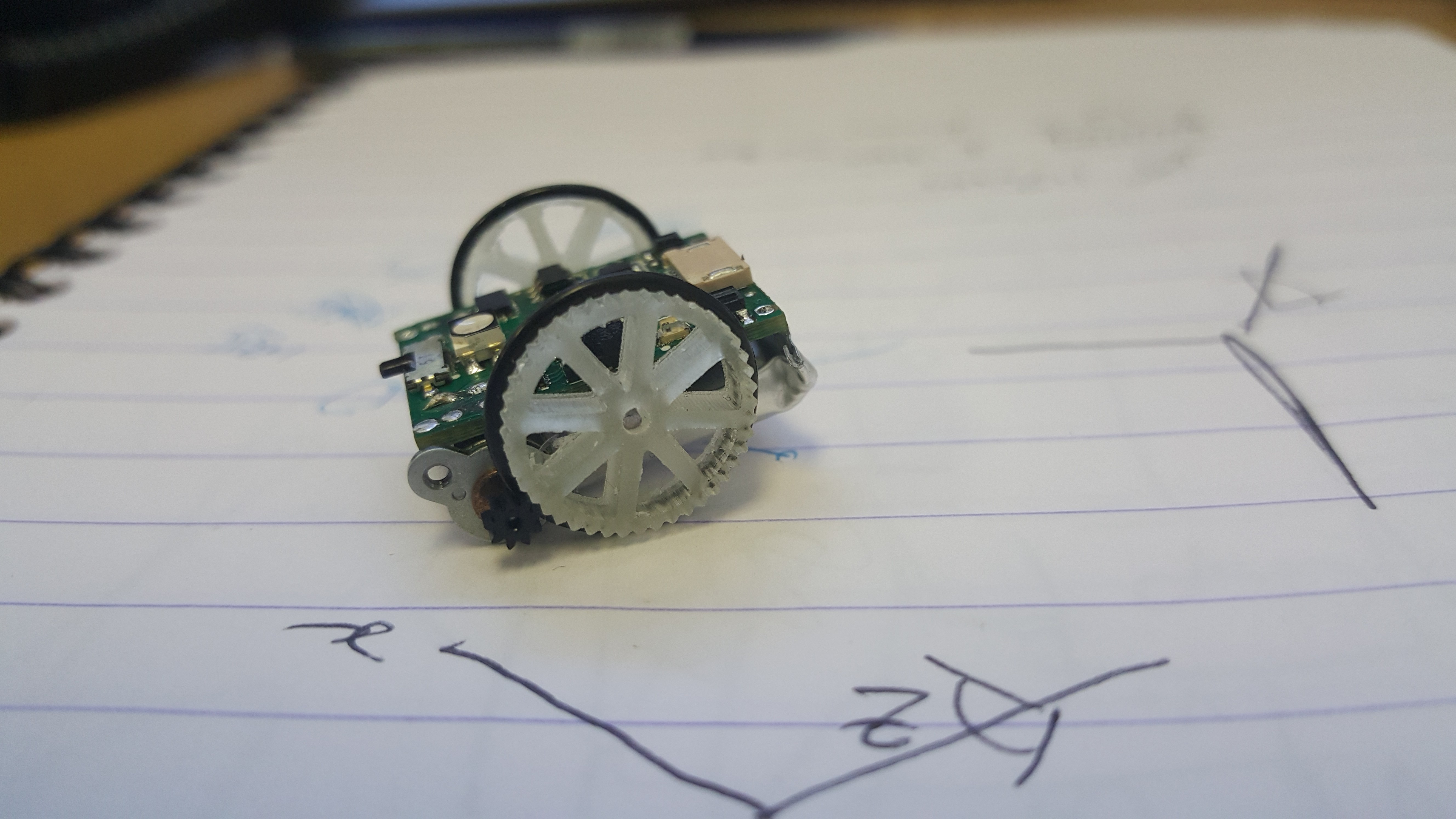
Fitting the wheels is a pain, any imperfections in them will make the motors stall, any misalignment of the shaft will make the motors stall. I think you get the idea, these are small robots and as such have limited torque, be prepared for a fiddly calibration of the drive train. This should be fixed in future versions with stronger motors, more precise wheels and a jig that aligns motors and shaft during assembly.
![]()
Hello from the little robots!
-
Robot construction, a bunch of 6: Part 1.
05/14/2016 at 15:03 • 0 commentsWe have had one robot working for a little while now, responding to manual remote control commands, the next step is to have something a little more 'swarm like''. 6 more robots is our target, and this log will show and describe the process of assembling them.
This post may also mirror many of the things said in this , as we were the ones to do the soldering section of that project, so if you want more pictures of a similar process, check there.
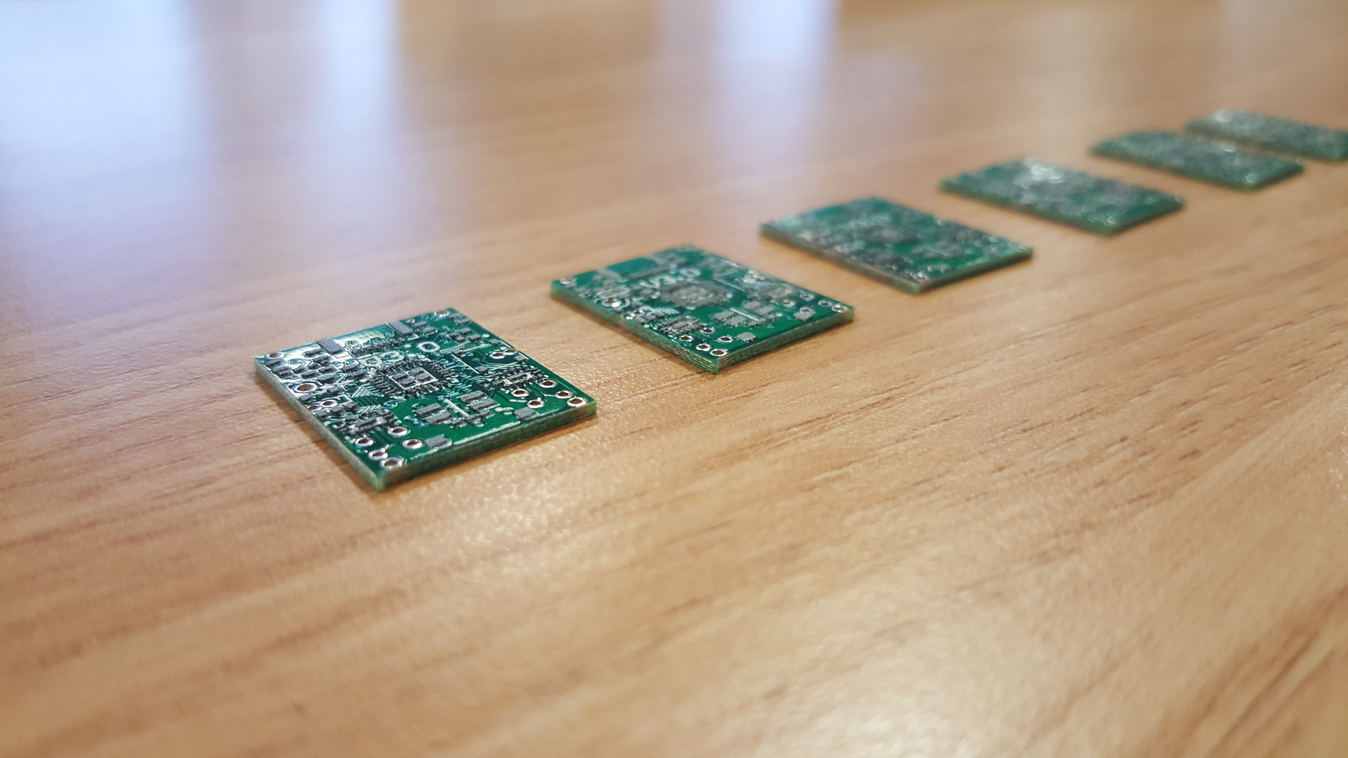
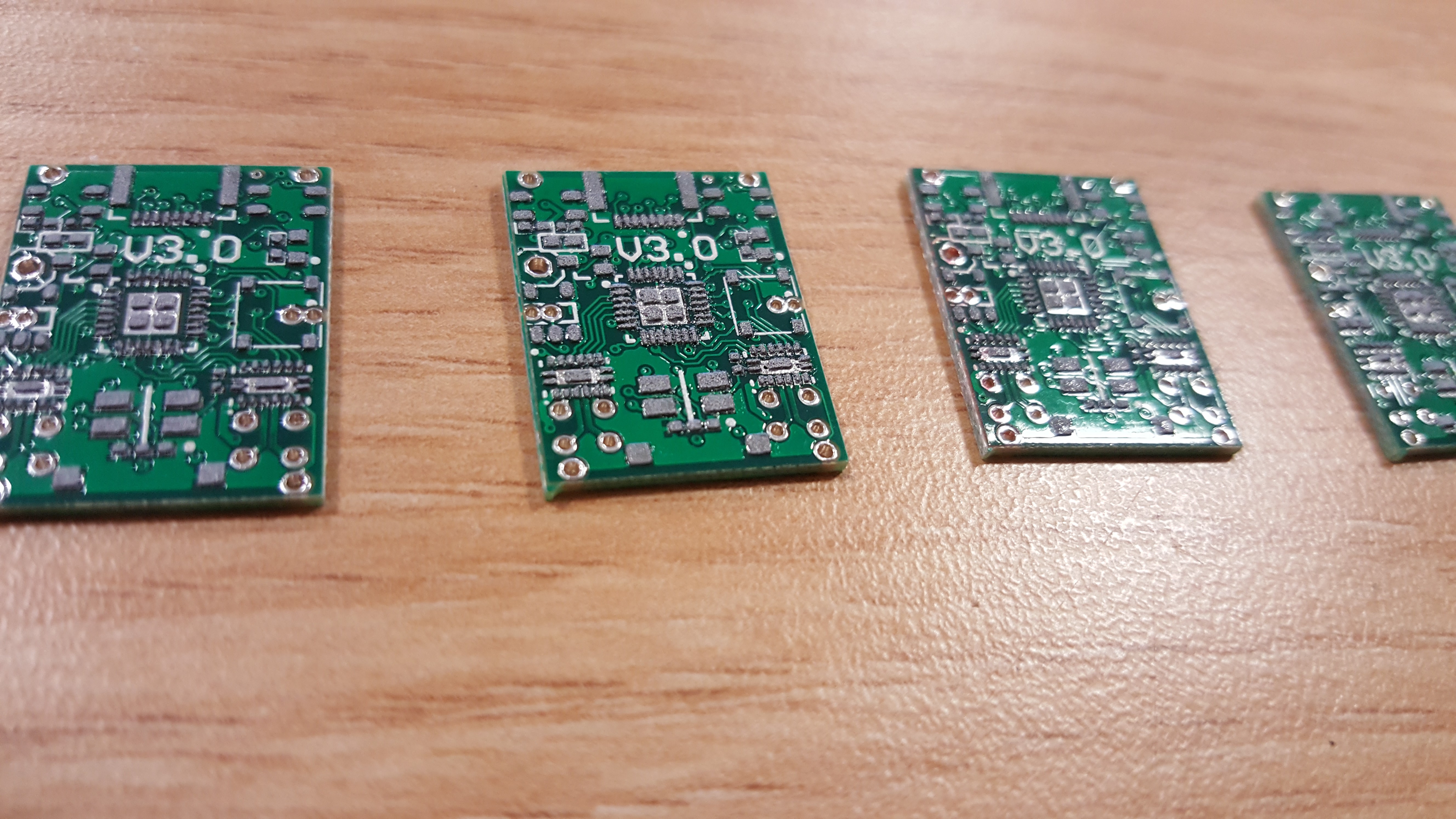
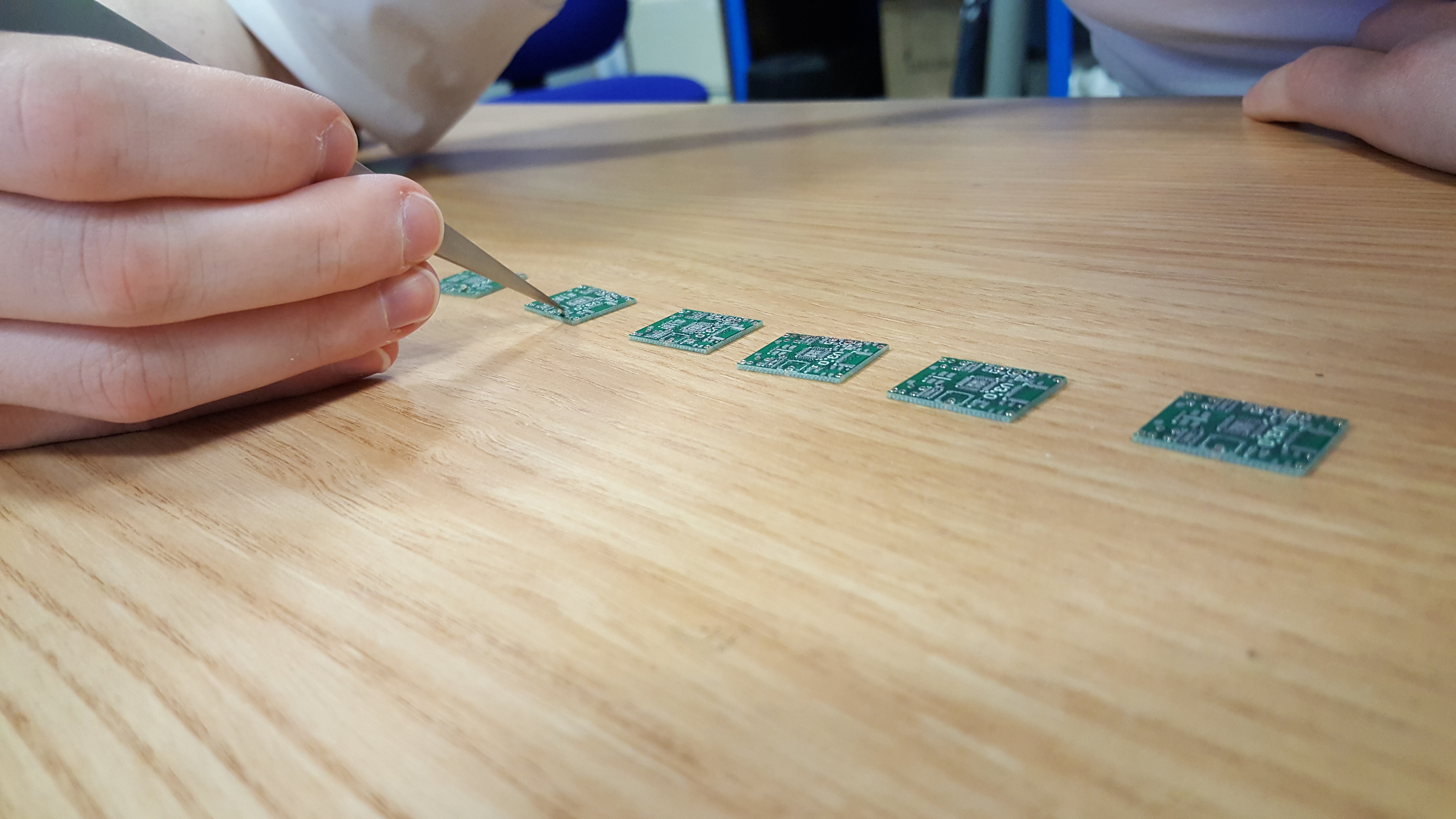
First you will need some PCB's. We used Elecrow for ours, their prices are good, especially for steel solder paste stencils, $18 for one with a fancy frame, nice! There are many other manufacturers that do a good job, so have a look to see which ones are quickest/cheapest delivering to your country. For this design we highly recommend using a proper steel stencil, rather than home brewing one, these parts are on the tiny side.
- Source the components, Farnel and RS are good. The full BOM will be published a little later, the design is still in flux.
- Lay a board flat on the table and line the stencil over the top. Using a credit card (that you no longer need) scrape the solder paste across the holes, then in a second pass remove the excess. There should be shiny steel visible everywhere apart from where the holes in the stencil are. The holes themselves should look evenly filled with paste.
- Lift the stencil, the board will likely stick to the bottom. Remove the board, avoiding smooshing the paste!
- With tweezers place all the components on the board being carful with the orientation of the ICs and the diodes, DO NOT PLACE THE BATTERY. (BOM + Circuit diagram + Board layout to come when the board is finalised)
- When all the parts are on one side, place in a SMD soldering oven if you have one. Alternatives include modified toaster ovens or a hot air gun. I would not recommend a hot plate. The board is double sided, so when doing the other side this won't work.
- When cooled flip the board and apply paste in a similar manner. The complication now is that the other side of the board is not flat. We just did the stenciling freestyle by trapping the board between the stencil and the table, though you can use shims to raise the board to allow it to be flat.
- Place the components on this side and reflow.
- Inspect carefully and remove shorts with a soldering iron and desoldering braid.
- Solder on the through hole components and the battery.
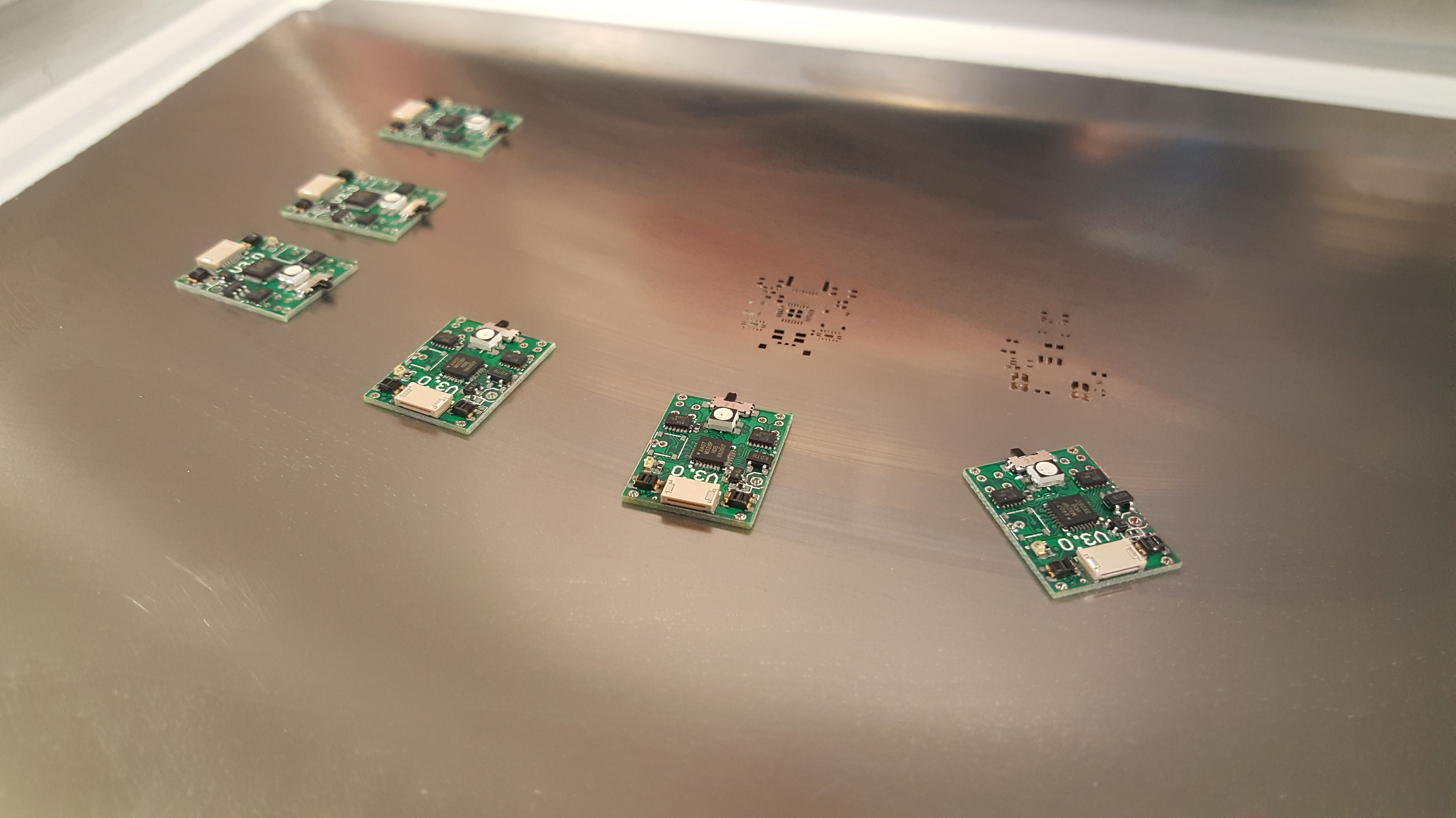
The paste should be nice and square, with well defined gaps between pads.
![]()
![]()
Go slowly, placing one variety at a time. Resistors and capacitors in this size have no markings, so if you mix them up, bad things ....
![]()
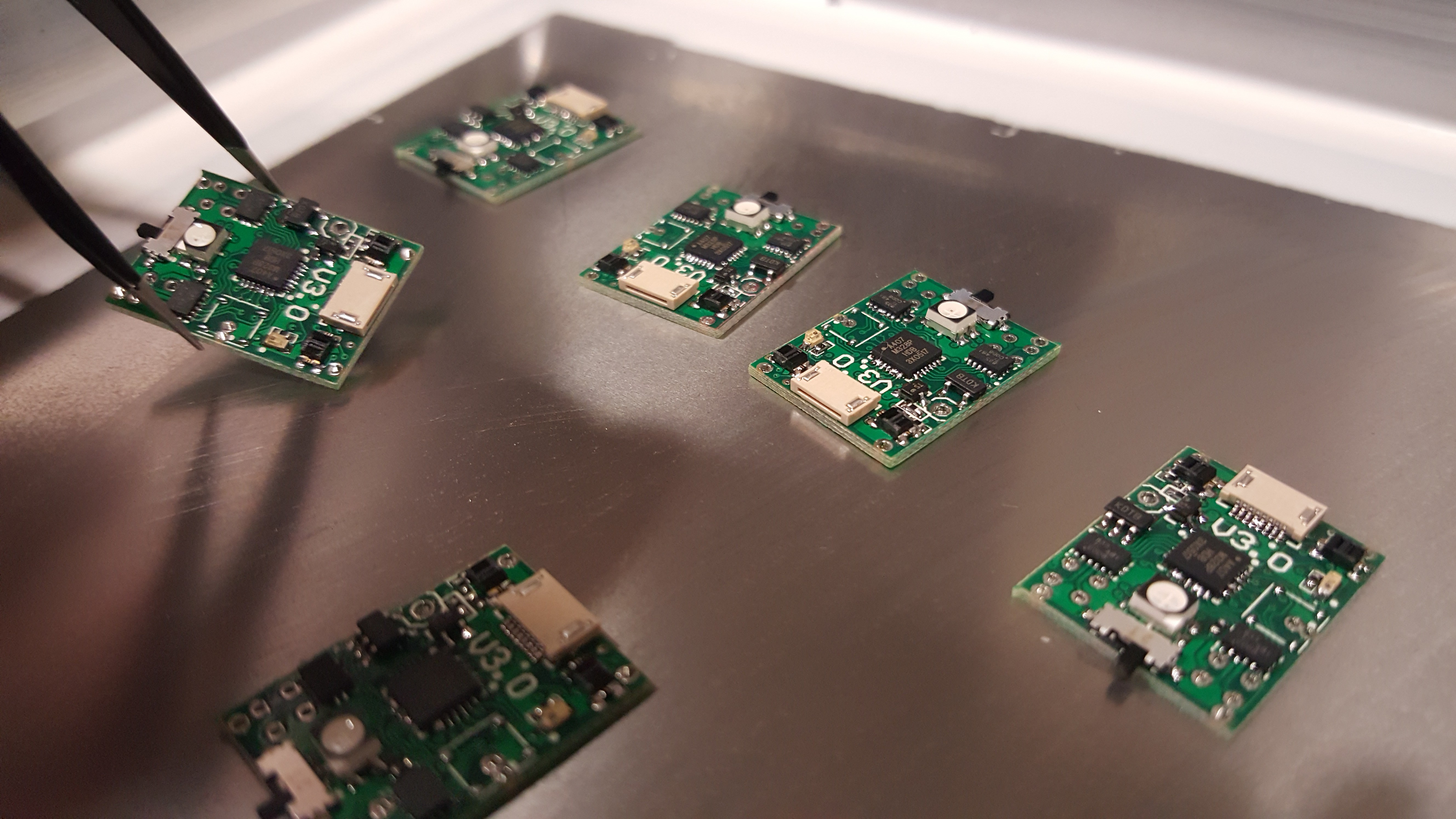
Carry them to the oven/airgun carefully, the surface tension of the paste should hold parts in place, but they are delicate!
![]()
After soldering the top. There are still shorts on these boards, an exercise for the reader.
![]()
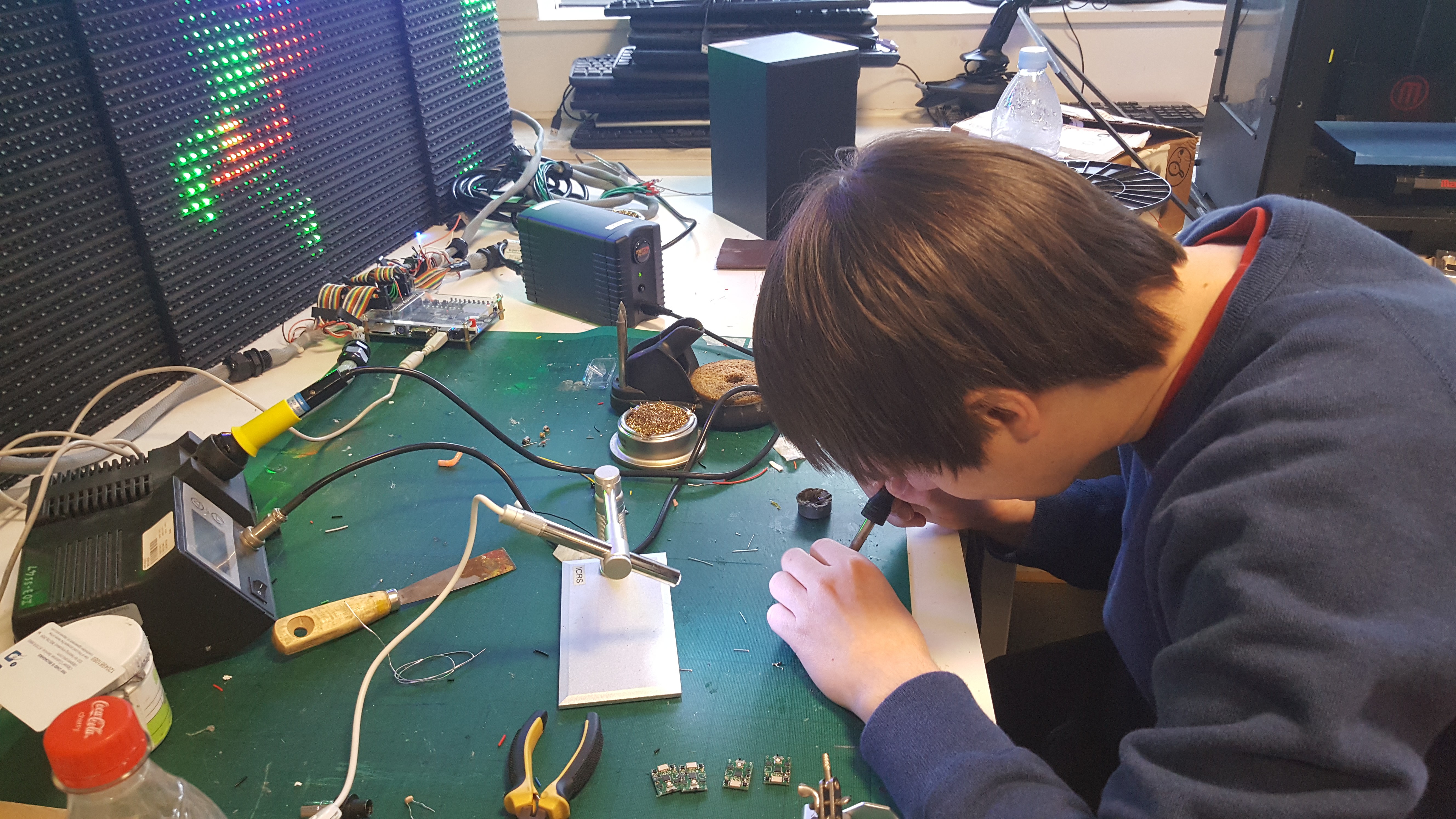
Rework the joints at your favourite messy desk.
![]()
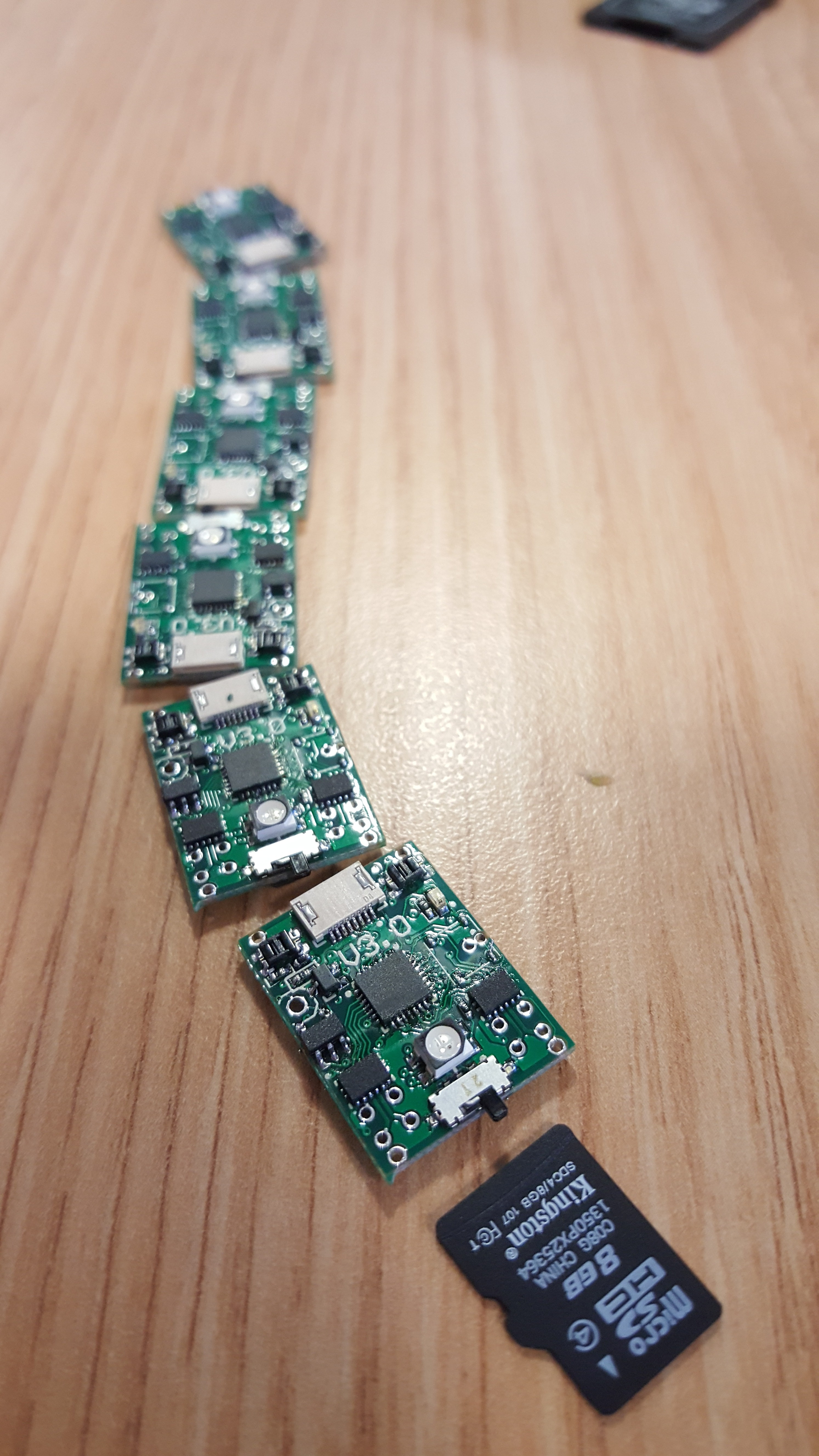
The bulk of the PCB work done.
![]()
![]()
-
Experiments in Wheels: Part 3
05/05/2016 at 16:38 • 2 commentsHello, once again I am here to talk about wheels, don't worry, next time will be something different, but for now, it is wheels.
First the video, because hell why not:
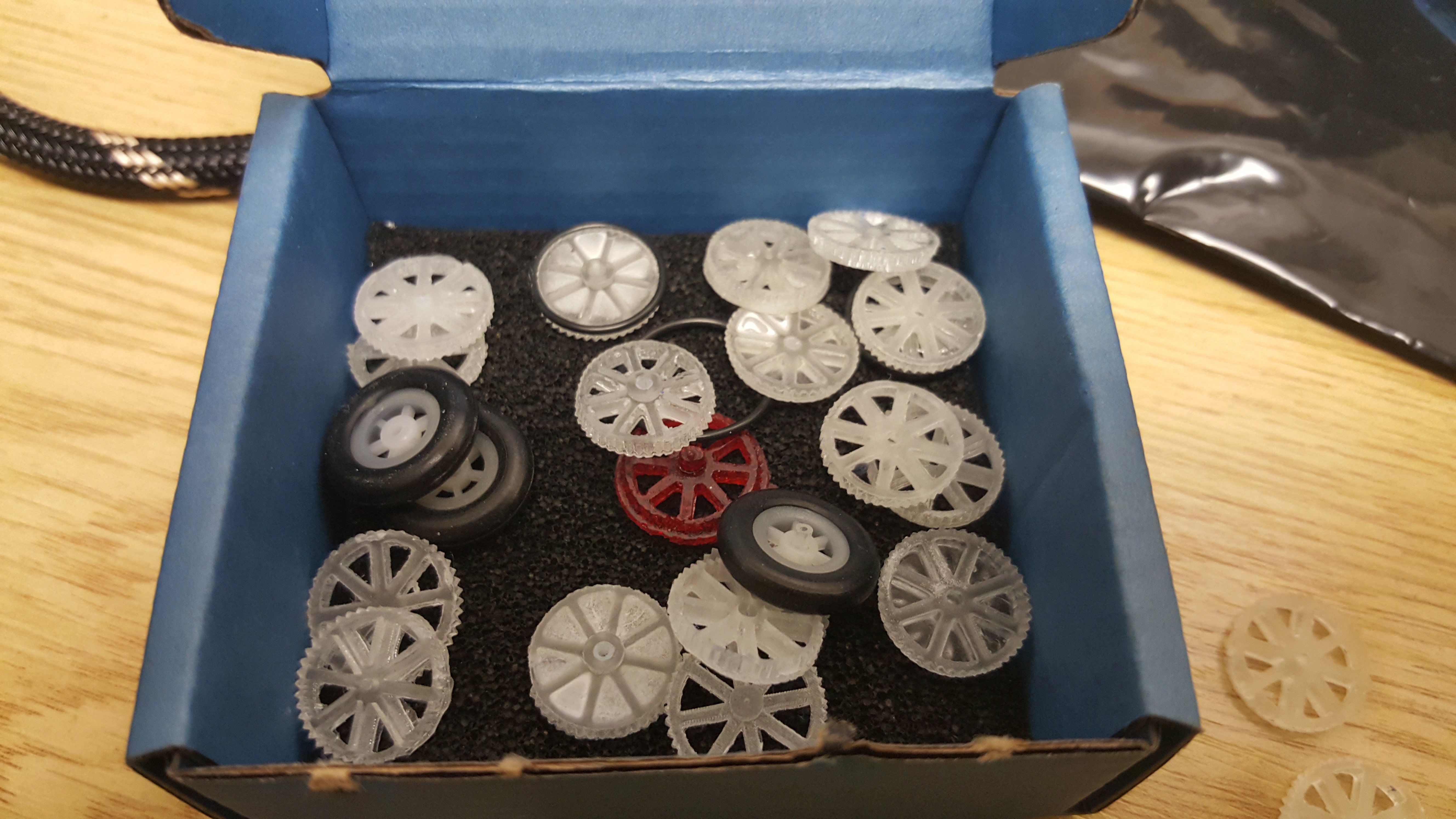
The wheels that I have settled on are made with a DLP driven, resin curing 3D printer. Whilst I would not recommend making a million like this, it is surprisingly expedient. On one bed I could fit something like 50 wheels, and have them completed in around 1 hour including clean up! For reference the printer I am using at the moment is the Roland ARM-10 that is in residence at the ICAH (Imperial College Advanced Hackspace) digital manufacturing lab.
![]()
An interesting thing to note about this design of wheels is that they do not need to have a retaining clip on the shaft to stop them slipping off. The rubber o-ring is behind the pinion gear on the motor, the pinion then does not allow the wheel to move sidways.
![]()
This image shows an interesting point about the DLP printing process. It is important to avoid having any critical components touching the build plate. Before we had the gear teeth touching the bed in order to have a boss to lengthen the bore on the other side. This time the side retaining the o-ring was against the build plate, and look how sharp those teeth look! Satisfying! Consequently these new wheels are much more consistent with each other and run much more smoothly.
![]()
The wheel attempts are racking up, but I think we are nearly there. The current wheels will do for now, later we might make the bore more tight to the axle, but that is mostly for aesthetics.
Micro Robots for Education
We aim to make multi-robot systems a viable way to introduce students to the delight that is robotics.
 Joshua Elsdon