 Swaleh Owais
I have attached a motor to the front roller. This task contained two components: Physically attaching the motor to the axle and implementing a controller for the motor.
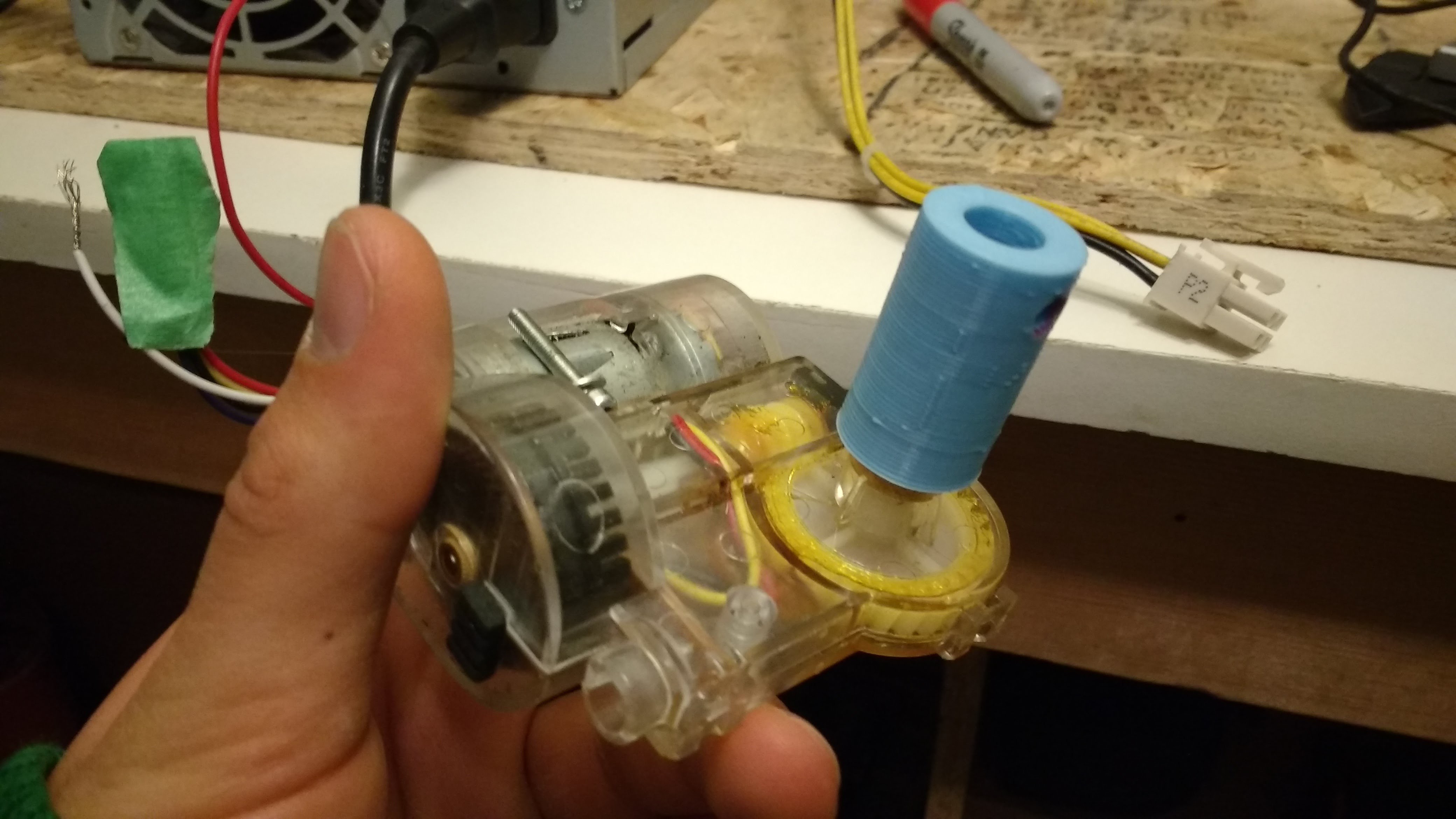
I upcycled the motor from an old robotic vacuum. The motor is a simple 12 V DC motor. The motor had an integrated optical sensor, but I was too lazy too incorporate this into my mechanism.
[Figure 1: Motor Salvaged from bObsweep Robotics Vacuum]
I designed a simple adapter that connects the motor to the front axle. I connected the motor to the axle and then I designed the mount that connects the motor to the bed. This order ensures that the motor axle is concentric to the roller axle.
[Figure 2: Axle Adapter Attached to Motor-]

[Figure 3: 8-32 Hole for Adapter]
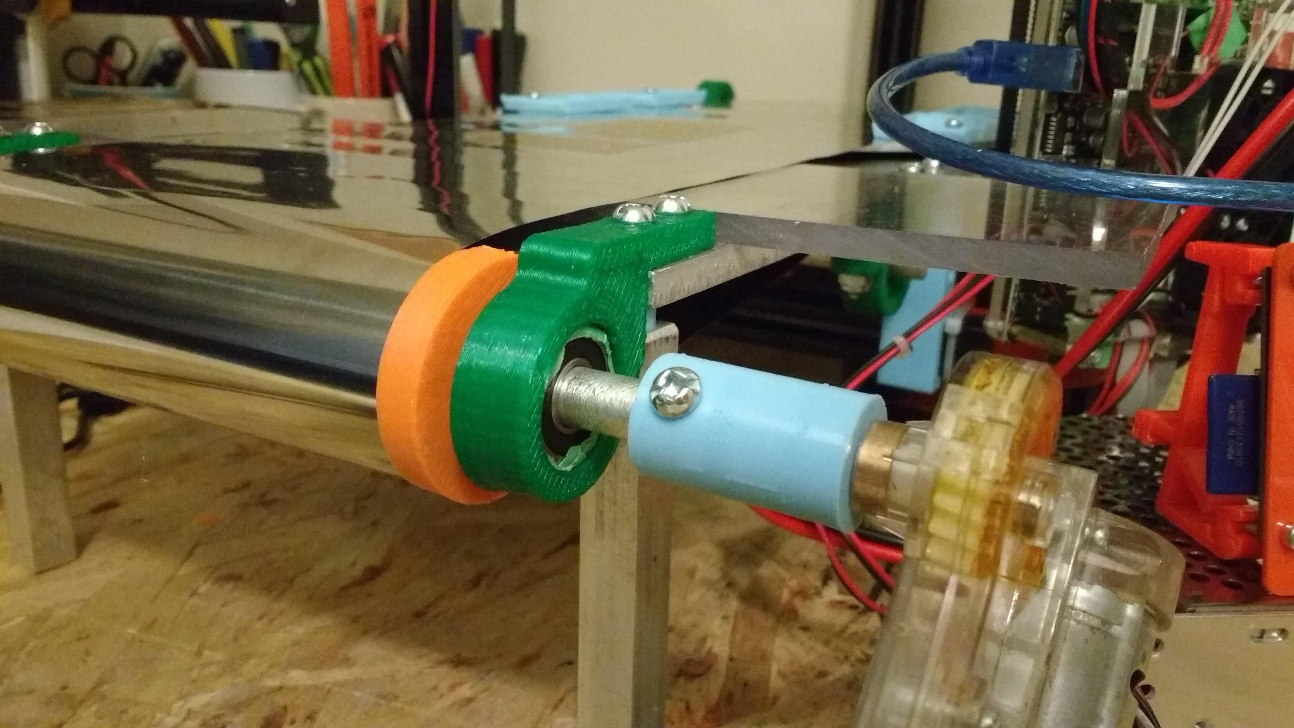
[Figure 4: Motor Connected to Front Roller]
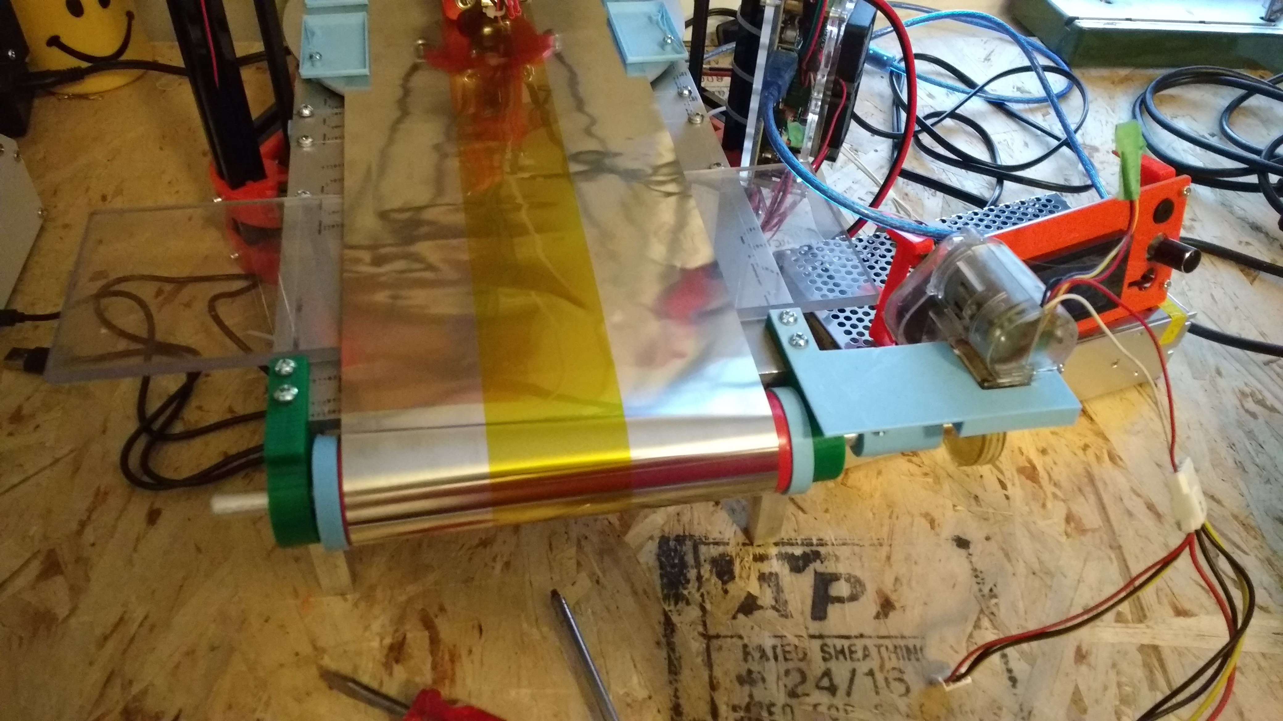
[Figure 5: Motor Secured to Bed with Motor Mount]
I powered the motor with an upcycled 120V computer power supply. Before adding logic to the circuit, I ran a few tests with the motor.
[Figure 6: Testing Printing on Conveyor Belt]
[Figure 7: Testing Ejection System]
It is important to note that the skirt of the print is not ejected by the conveyor in the shown example. After adding the shear, the skirt is also removed consistently.
Discussions
Become a Hackaday.io Member
Create an account to leave a comment. Already have an account? Log In.