jlbrian7
-
Pics for Stack Question
08/02/2014 at 11:57 • 0 comments"Blob"
![]()
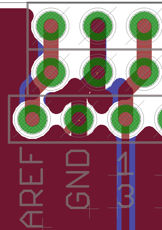
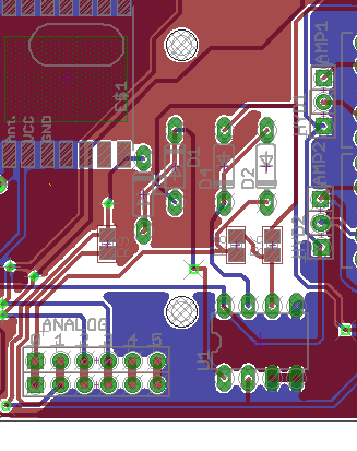
Here you can see the copper around the GND pins. I took this out so that the GND here looked like that of AREF and 13, but I ran wires on the top and bottom of the board.
![]()
Here I was concerned about the white space, but since I did not have any trouble with this board version that did not have a copper pour I left it as it is.
-
v1r5
07/29/2014 at 12:32 • 0 commentsFor the final board I am going to use smd diodes, and am considering the digital pot -
AD5207BRUZ10-RL7
to adjust to different operating conditions.
-
Ground Fault Test
07/28/2014 at 02:21 • 0 commentsI hooked up the ground fault test box again, and took some measurements. With a calculated ground fault of 0.09A I was getting an peak A rms reading on the arduino of 0.05A it was regular but not constant.
I was able to measure a calculated 0.1A ground fault with the meter and the arduino. The arduino still measured 0.05A but the meter measured 0.9A. This wasn't a reliable measurement though.
The detectable amperage is higher than the standard which is 0.06A at the highest, but I didn't set out to build a gfci and I am pleased with the results.
I did check the arduino at a measured 0.6A calculated load and measured 0.52 so I am happy that it was closer at this level. I will continue to test the circuit and finish with three graphs, Calculated, Meter, and Arduino and compare the results, but I have to get a better dmm first.
-
Power Connector
07/25/2014 at 02:48 • 0 commentsThis is probably old news for most people, but I just learned something today.
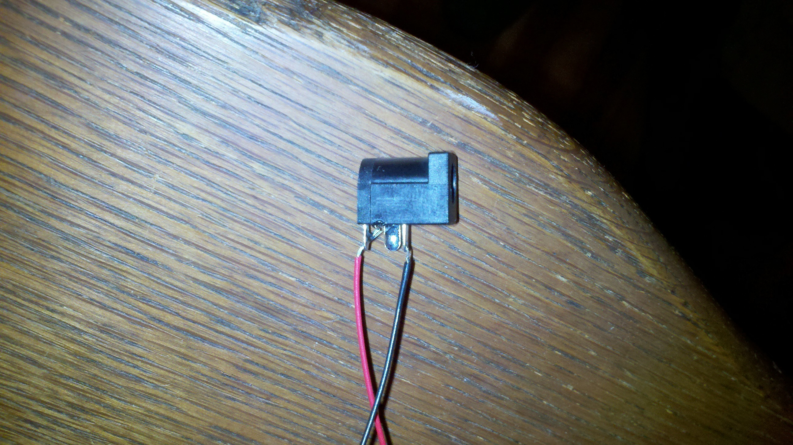
![]()
On the DC power connector above the red wire is connected to the center pin and the black is connected to the casing contact. When nothing is plugged in, the center connection that is not connected has continuity with the connection with the black wire.
When a power cable is inserted you lose continuity with the terminal that is not connected. I believe that it is irrelevant now because I have revised my board but this was an issue with the way I layed out v2r0. The chinese arduinos would work as is, but I was having some strange problems with the sparkfun arduinos.
It is a notable fail on my part because several weeks ago when I assembled the first board I had originally used the sparkfun arduino and ran into the strange problem and assumed that I had created a solder bridge somewhere because I was lacking confidence in my smd soldering abilities. I slavaged some parts and tossed the board aside.
The second build, the one in the main project picture, I used the chinese board because I did not want to risk damaging a $10 board when I had several $3 boards laying around.
Tonight I did some troubleshooting while building up a couple more boards and found the problem... I am almost always right to assume that if there is a problem it is because I did something wrong, but every now and then I need to take a closer look at the components. I didn't know DC jacks had a switch inside.
-
v1r4
07/23/2014 at 17:01 • 0 commentsJust got my first boards that I have done with a copper pour. I was dissapointed when I opened the package to see that they did not bevel the edges of the board. I am not entirely sure that it wasn't the board house, but I think that it is because the way I created the polygon for the ground. I'll post here for others to be mindful of it and so that I remember to come back to it when I find the solution.
-
Software
07/20/2014 at 12:28 • 0 commentsAs I said in the previous post I have a clear idea of what I want in order to call v1 and v2 complete, so right now I am going to stop development on the boards (other than what is necessary for the one I am going to put in the field) and return to the development of the UI. Progress is probably going to slow way down.
-
Selling boards online
07/20/2014 at 12:24 • 0 commentsWhen I started this project I said that I intended to sell the boards online, and I still intend to. The hold up has been taking the time to figure out how much shipping should be, ordering packing materials, and having a build that I am comfortable distributing.
I am almost to the point of calling v1 complete, and I have a good idea of what I want to see for v2 to call it complete. These I see as hobbyist boards or boards for people with more advanced skills but not a consumer product. I have an idea for a v3 that will lose the arduino foot print and will use the hlk-rm04 instead of the electric imp.
v3 is going to take more time to develop because the hlk-rm04 is completely new to me and what I want to see from the system I have in mind is more complicated, but in the end should be a drop in embedded system that is capable of being used in a number of household/industrial applications.
Long story short I hope to start selling v1 and v2 boards late this winter.
-
Volt Amp Board
07/18/2014 at 04:13 • 1 commentI am worried about this board because there are a couple of components I have never used before on it.
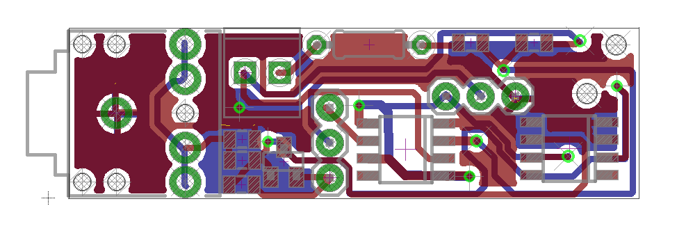
![]()
What I am wanting to do is bring out the remaining analog pins on the arduino to audio jacks that also supply 5v and gnd. From there you can plug anything you want into them. This board will have a whip on it with an audio plug on the end, and the audio jack here is so you can plug a current transformer into it, and the connector is to connect wires to the mains ( 1 board for each main line coming in) this will go to an AD629 (the part that worries me) . The other part that has me worried is the BAV99 that I replaced the diodes from my original board with.
The rocket fuel tank monitor that I used was using two of them as a bridge rectifier (that is my best guess because they were marked A7W and it would seem right, at least to me). That makes me think that they should be fine, but still a little worried about it. (Random tangent - I planned on ordering them anyway to rebuild the power circuit from the tank sensor reciever before I put my documentation online. If I get it right it looks like an easy compact way to power a circuit off of 120vac).
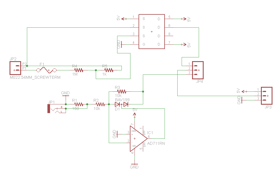
Here is a rough schematic of the board design...
![]()
The part with the S's and D's is what I am using to represent the AD629 (the datasheet will have to suffice for now) until I create the part in Eagle, the part labeled BAV199 will be saved as BAV99, and the part labeled AD711RN is schematically correct but I am using TS1851IDT ( I can't pretend to know much about any of this, but I chose to keep this op amp on my bench because of the operating range).
If anyone has any advice before I build this I am all ears!
-
Nest
07/16/2014 at 13:51 • 0 comments![]()
While I was waiting on boards and parts I started assembling this. My answer to the Nest thermostat, ugly isn't it. Since I got an email yesterday that sparkfun is filling my order for sd card holders and I have 9 more boards to use up I am going to replace this with my "Power Monitor", a protoshield, and a serial lcd. While the thermostat itself is not smart I will send the data to the database, and make it so that the computer can make the "smart" temperature choices and control the thermostat. This is my second Nest rebuild, after first reading about their products before google bought them I built this...
![]()
The april board pulled power from the battery and was connected to the test button and the speaker. It would read the battery level (which this setup would drain in about a half an hour), could remotely test the unit through a web interface, and would provide feedback to my xively feed. The feedback was based on the number of pulses sent to the speaker and could report CO2, Fire, or Test. This would have only been practical if the smoke/co2 alarm was connected to house power, but to my wife's frustration I had fun going to work and hitting the test button. I had broken the link to xively one night playing around with the code and forgot about it the next day. When I was showing it off to a coworker I was disappointed that my feed was not updating, but when my phone rang it proved to be a closed loop system just the same.
-
Software
07/15/2014 at 13:29 • 0 commentsIn the video I mentioned Xively and Emoncms, but I will also set up the new service from sparkfun and see how that works for me. I will host it my self, but I think that I will also push data to their service as well.