Close
0%
0%

2300Mhz LTE Yagi

How to design and build a 2300Mhz band LTE Yagi for a wireless broadband connection

Similar projects worth following
A DIY project that explores how to design and make a LTE Yagi for the 2300Mhz band, taking you through the design process and how to build it without too much effort or money.

The problem:

I have suffered for years with a poor ADSL connection being over 5km to my nearest exchange, and constantly had dropouts and irregular speeds between 1.5Mbps and 3Mbps. I used a Billion 7800N modem which has the Broadcom DSL chipset (the most tolerant to long lines) and the Billion could adjust a number of the ADSL settings which helped tweak the speed but you can' t beat physics so it was a constant battle of compromises between reliability and speed. With a family of three teenagers who love to stream music and movies you can imagine the frustrations with the internet connection. In Australia with long distances and sprawling suburbs it is fairly common to have marginal ADSL connection, and fibre / cable is only an option for some suburbs, not mine.

When my ISP Optus had a long line outage once they gave us a mobile wireless broadband hotspot to tide us over for a few days but being in a mobile phone blackspot I knew it wouldn't work well, and I only got a marginal connection and slow speeds with the hotspot only picking up a faint signal at one location in the house. So along with the high costs of wireless broadband in Australia with low data caps, it seemed wireless broadband wouldn't be an answer for me.

Recently a local wireless ISP VividWireless released a LTE broadband product with unlimited downloads at a reasonable price, the only Australian wireless ISP to do this (that I know of), which solves the issue of low data caps. And when I checked their site it showed that I wasn't in coverage range (not unexpected) but not too far away from their coverage edge. They used the Optus wireless network and have a local cell tower not too far away which I knew would get a signal albeit a poor one as my hotspot can just pick it up. They also limit the speed of the wireless connection to 10/1 Mbps which isn't fast for LTE however it goes a long way to not overloading the limited bandwidth of the cell tower - having unlimited downloads and fast LTE speeds at a good price is a recipe for a popular service especially in a suburb like mine where ADSL is marginal, making a wireless service attractive and quickly congested. So its good that this is a speed limited service - 10Mbps is 4x as fast as I typically get on ADSL and if it is more reliable then it may be an option if I can solve the reception issue.

Being a qualified (but not practicing) Electronics Engineer and remembering sitting through all those boring (and maths intensive) 4th year lectures about antenna theory and radar that I never got to use in practice I thought - why not have a go at trying my hand at a DIY antenna? So I took the plunge and bought the wireless modem and signed up to a month of the service - worst case I could resell the modem if I couldn't get it to work. Installing and setting up the wireless modem I had the same experience as the hotspot (as expected), barely working in only one spot in the house and very marginal (RSSI -91dBm), about 3Mbps with dropouts, likely worse when it rains. Spending a day trying different spots in the house did locate a place on the roof where it would receive -89dBm and if raised the modem high enough on that spot I got -83dBm which should be sufficient for a fast and reliable signal, and with a proper antenna I might even be able to get in the -70's.

Antenna options

Easiest option would be to buy an antenna however it seems the LTE frequency the ISP uses 2310 - 2400 Mhz isn't a popular one, adjacent to the 2.4Ghz wifi spectrum, but sufficiently different that an antenna designed for wifi wouldn't be as sensitive or effective as one specifically designed for the Optus / Vivid spectrum. There don't seem to be any antennas specifically designed for the 2300Mhz LTE band although there are a lot of wide bandwidth antennas that span this range, but I recall from my lectures on antenna theory that bandwidth and gain are a tradeoff so that large bandwidth wouldn't be high gain (even if advertised as such - seems lots of...

Read more »
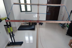
  • 1 × 1m 6.3mm aluminium rod (not hollow)
  • 1 × 5/64 1.98mm drill bit
  • 1 × Sharpie permanent marker
  • 1 × 200mm of 2mm steel wire
  • 1 × 6.5m of RG213 coax

View all 8 components

  • Testing the Yagi

    deandob05/02/2016 at 09:40 0 comments

    Connecting up the SMA coax adaptor to the modem, switching over to the external antenna on the Huawei modem without mounting the Yagi did give me a signal but not a very strong one.

    Wireless Statistics Before
    RSRQ: -10dB
    RSRP: -116dBm
    RSSI: -87dBm
    SINR: -1dB
    One bar
    Speedtest: 8.85Mbps download, 55mSec ping, 0.99Mbps upload

    Wireless Statistics After
    RSRQ: -5dB
    RSRP: -112dBm
    RSSI: -83dBm
    SINR: -11dB
    Speedtest: 9.79Mbps download, 55mSec ping, 0.99Mbps upload

    (speedtest is limited by the ISP's speed throttling).

    A little bit of a difference, but now I have the modem mounted inside the house not high up outside next to the roof for the best signal (which was never a long term proposition). I also have 6m of RG213 cable which has a loss of about 3.5dB as well as a RG213 connector and SMA adaptor likely I'm losing another 1.5db there. I think the internal antenna in the Huawei wireless modem is pretty decent because the modem box size is large and with the high LTE frequencies the ¼ wave size is only 32mm so certainly possible to have a decent internal antenna in the unit.

    The speedtest tells me the radio link quality isn't the limiting factor both before and after, it is hitting the Vivid throttling first. The slight speed variation from before and after is likely the tower / net congestion.

    This means my Yagi is getting about 7dB better than the internal antenna which isn't bad and unless I have made an error in the calculations or assembly it is about as good as you are going to get. My Yagi is designed for 12.5db of gain from 2300Mhz to 2400Mhz with 50 ohms impedance at those frequencies (so no special impedance matching needed). The Yagi is designed to use a normal dipole (not folded) and a Pawsey stub to convert from the balanced dipole to the unbalanced coax.

View project log

  • 1
    Step 1

    Making the Yagi

    1) Use the dimension for the elements from the design I posted above to measure and cut the elements. 2mm fencing wire & some small wire cutters does the job, try to get the lengths as accurate as possible.

    2) Use a sharpie to draw a straight line on the 6.3mm Bunnings aluminium rod. Use this line to measure out the spacing between the elements and use a good nail to indent the rod where the elements should go so the drill bit catches at this point.

    3) Buy a 5/64 (1.98mm) drill bit which is slightly smaller than the 2mm wire creating a force fit for the wire when it goes through the hole in the aluminium rod, making an electrical connection.

    4) Drill a 2mm hole at the 410mm point on the sharpie line and use a nail through this hole to secure the rod to a long bit of timber. This secures rod with the sharpie line on the top of the rod and ensures all holes are drilled at the same angle. I didn't do this step when I first tried and the holes weren't all drilled in the same plane, so had to start again.

    5) Drill all the element holes, ideally with a drill press which will ensure the bit is perpendicular to the rod and the holes on the other side of the rod will line up.

    6) With a small hammer gently tap all the element wire into the drilled holes - ensure the right length wire goes into the right hole.

    7) Use a ruler to ensure the wire on each side is equidistant length to the rod, using small taps on a hammer to adjust. Try not to shift the wire too many times in the hole as the aluminium hole will widen which means you won't get an electrical connection and the wire may shift too easily messing up the length on both sides of the wire (i.e. no longer equidistant to the rod).

    Using this technique the holes were perfect and all the elements when fitted had a snug fit and lined up in the same plane nice and straight.

    Spray with galvanising paint to protect the steel (especially as we have aluminium and steel touching which can cause galvanic corrosion when exposed to the elements) and the paint also binds the elements to stop them from sliding (although they should be pretty tight in the hole), it also makes it look good!

    8) for the active element I used the coax itself to avoid having to solder an extra connection (never a good idea with RF), and stripped the coax and shield back to make a dipole of the right length, soldering the wire to give it some stiffness and using a small diameter plastic sheath to protect the wire. I then mounted the coax so that the coax ends for the dipole sits in the same plane as the elements.

    9) For the balanced to unbalanced balun I used a 32mm (1/4 wavelength of 2350Mhz) piece of RG213 coax and soldered the braid to the feed coax inner conductor and the other end to the feed braid.

    10) Silicon to seal around the coax ends to protect from the elements.

    11) Used a 30mm plastic conduit (not metal!) to mount the antenna above the roofline and orientate it at 45 degrees and point towards the cell tower (check the modem RSSI values while moving the Yagi around to get the best direction). To mount the Yagi onto the conduit I used the handle from a squeegee window washer that used a rod about the same size as the Yagi boom so it clipped onto the Yagi and the handle end inserted into the conduit.

    Here is a link to a comprehensive LTE Yagi build: http://bcbj.org/antennae/lte_yagi_diy.htm

View all instructions

Enjoy this project?

Share

Discussions

Similar Projects

Does this project spark your interest?

Become a member to follow this project and never miss any updates