 caver.adam
I've been making progress on the CAD modelling for the project. I've got a draft model of all of the hardware at this point. This weekend I'll start printing/testing components.
I decided to go with a double herringbone gear for connecting the yaw motor to the shaft passing through the bearing. This made the assembly a bit more difficult because the gears have to come together as a specific angle, but I think the strength will be worth it. I also decided to use a prime number of teeth on the gear which is going to make the possible angles a bit odd in the programming but should drastically reduce wear on the 3d printed gears.
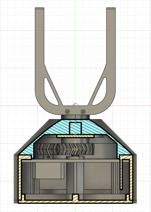
Based on the field-goal portion so far, it looks like this design is going to be a lot more stable than the last one. I worry a bit that I may have gone a bit overkill on the size of the body, but it should have plenty of space for the bearing, motor, gears, and electronics.
Discussions
Become a Hackaday.io Member
Create an account to leave a comment. Already have an account? Log In.