caver.adam
-
12V and 5V are not compatible...Oops!
07/31/2016 at 20:01 • 1 commentLast weekend I was hooking up the electronics and was distracted when I plugged a 12v source into a 5v pin on the stepper driver. The smoke was a clear sign of my mistake...and the voltage went back and destroyed my arduino while I was at it. Now I'll have to order a new arduino...
-
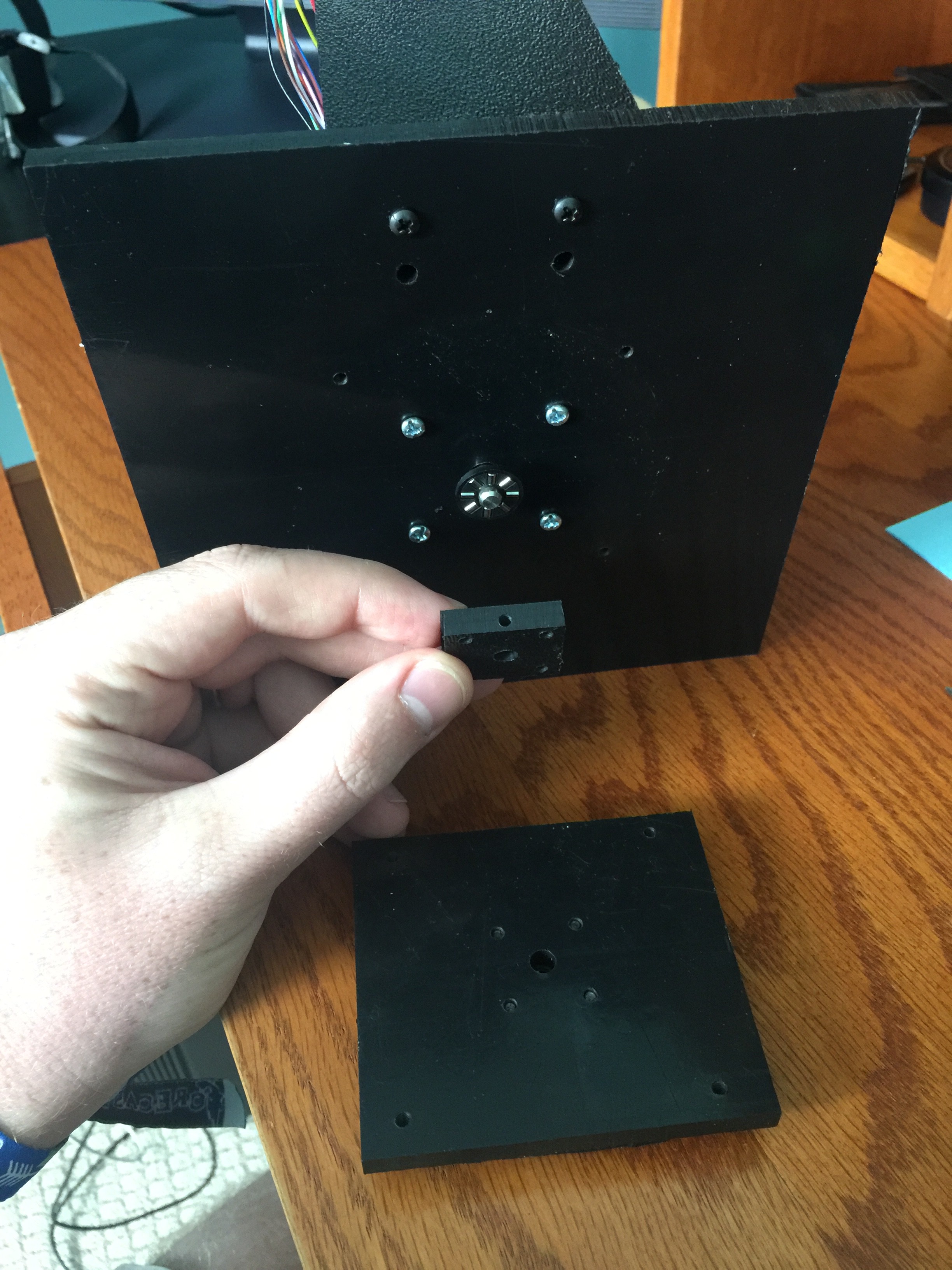
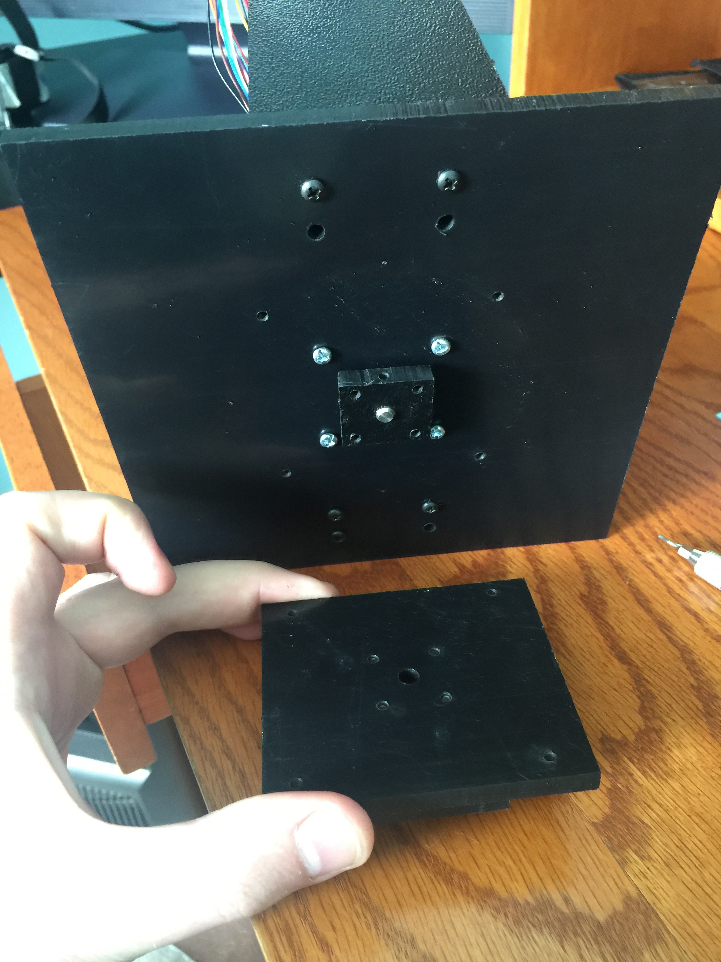
Replacing lazy Susan with thrust washer
07/18/2016 at 13:04 • 0 commentsI had too many problems aligning the lazy Susan so I decided to try a thrust washer and dual set screws on the shaft. Seems to work so far.
![]()
![]()
![]()
-
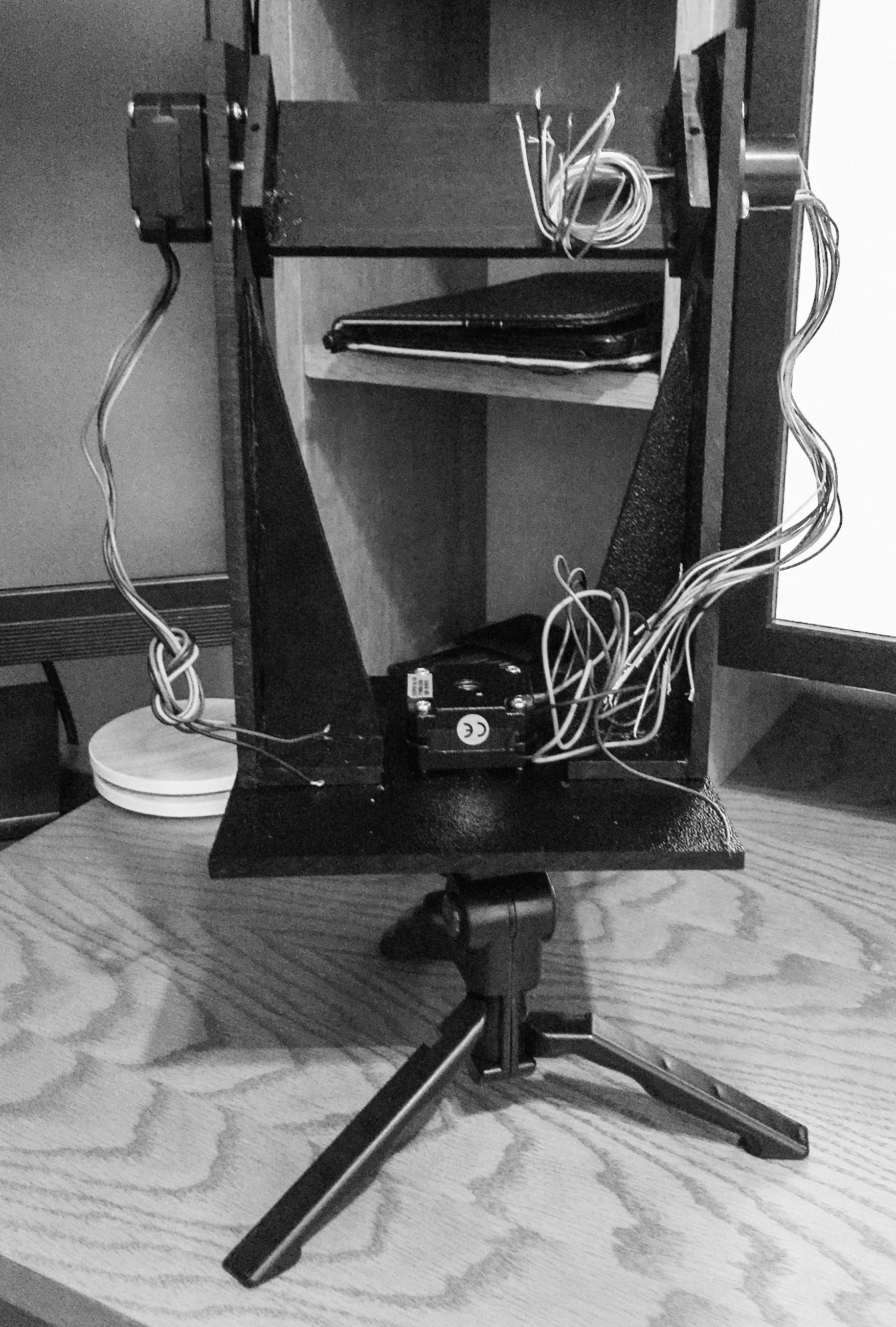
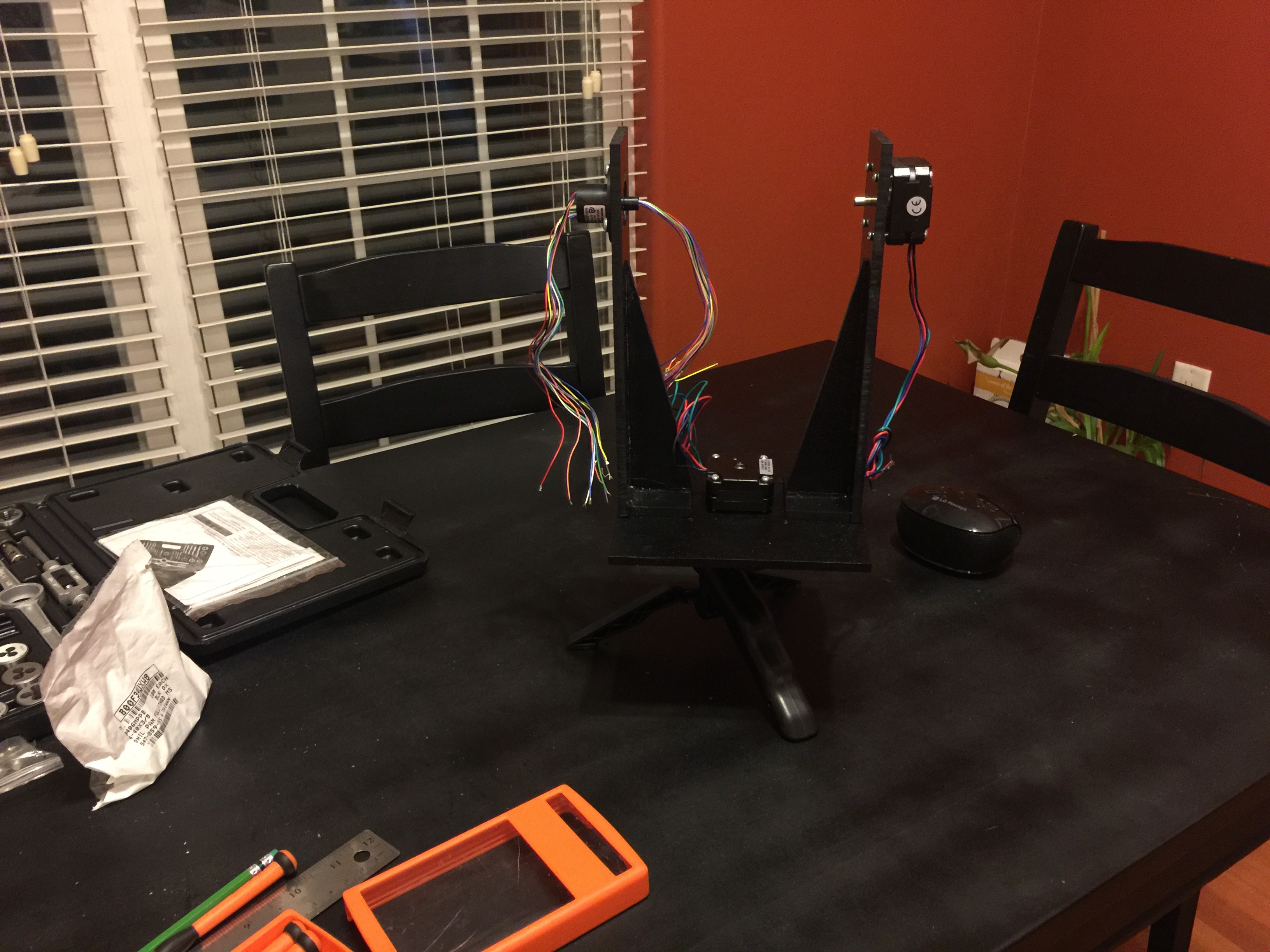
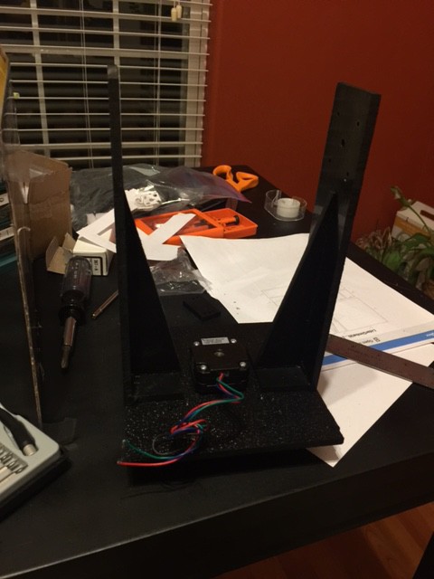
Mechanical assembly close to done
07/13/2016 at 18:03 • 0 commentsInitial proof of concept prototype getting close. Next time I 3D print for beauty...
![]()
-
More assembly...
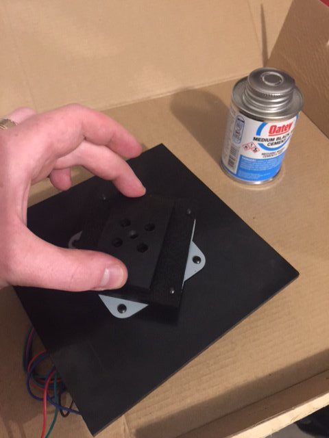
07/12/2016 at 02:18 • 0 commentsAll the pieces are now drilled and ready for assembly. The glue is setting on the carriage so final mechanical assembly will have to wait until tomorrow. Next step is to solder my arduino [clone] and battery holders. Then load them up and see what happens.
I had to remove the lazy Susan to fix the torque issue. Project is a bit wobbly until I can get a thrust washer to put in there to help support the load. But it works well enough to keep working while I wait for the part. Maybe at the hackerspace someone will help me center the lazy Susan. Who knows.
![]()
-
Assembling prototype gimbal
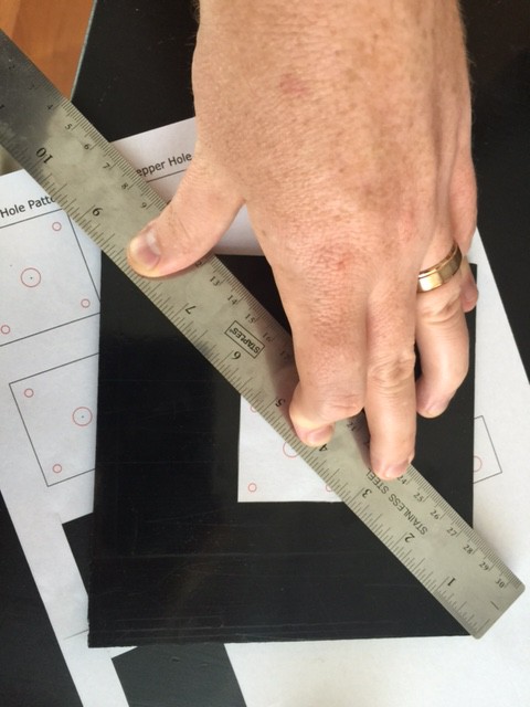
07/11/2016 at 03:18 • 1 commentToday I went into the drilling and assembly phase. I used Inkscape to create drill patterns for each of the pieces. I measured and then taped the drill patterns to the base.
![]()
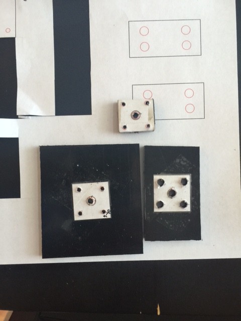
Then I drilled pieces in the order that will be discussed in a later instruction. I also tapped each piece immediately after I drilled it. Although, that was more so I could see the assembly coming together. It's going to take me some time to put more information up on the assembly portion into the instructions section. The alignment of the shaft with the lazy susan is off and is creating increased resistance during rotation (and noise). I'm going to need to fix the alignment issue another day. Maybe on Tuesday when I go down to the Lvl1 hackerspace.
![]()
![]()
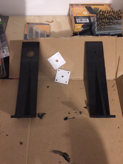
The base portion which connects the yaw motor to the tripod is complete (except that one alignment fix). I've also made the uprights and drilled most of the holes. I need to drill the 3 remaining holes and alight the uprights next before I start working on the LIDAR carriage.
![]()
![]()
![]()
Here's a short video just because:
-
Cutting the gimbal
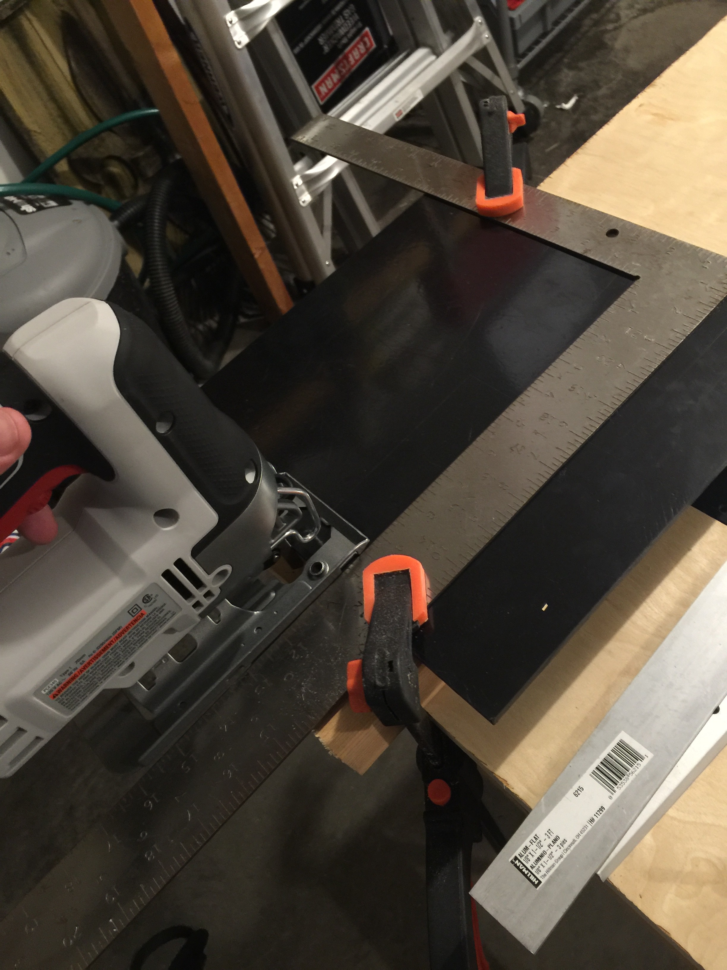
07/07/2016 at 01:43 • 0 commentsTonight I decided to make some time and cut the gimbal pieces. I ended up doing by hand because I wanted to use ABS and the local hackerspace has problems with neighbor complaints if they put something smelly in the laser cutter. So good old jigsaw to the rescue.
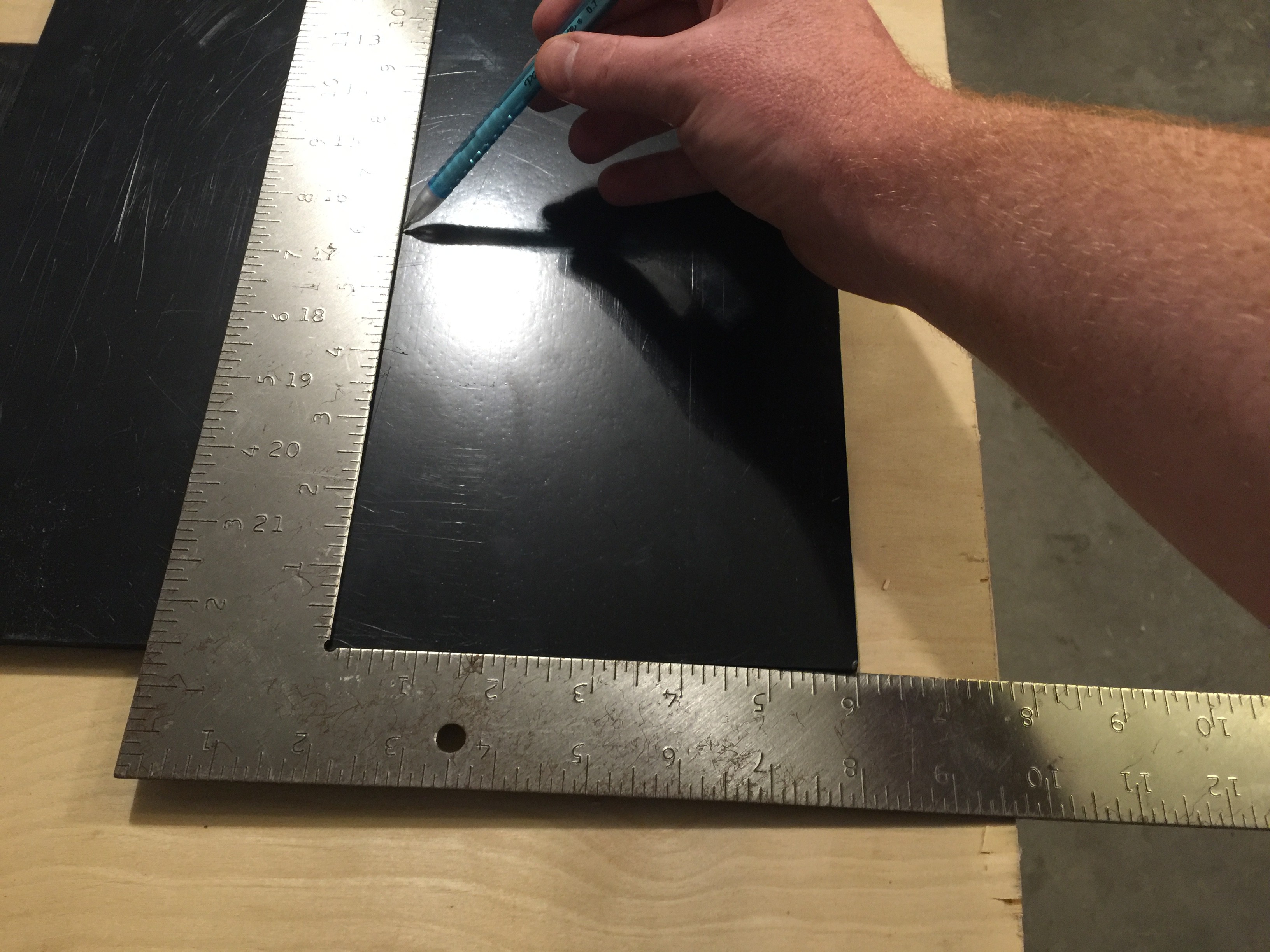
Throughout the process I kept one [fairly straight] edge available to measure from. My square showed it was pretty straight as it came from my source. This meant if I got a little crooked on a cut I could measure from the straight edge instead of the crooked edge.
I used my laser cutter file as a guide and started by cutting one piece at a time. At first I was using a straight edge to keep the jigsaw straight, but I was having a problem with the blade heating up and starting to melt the plastic. As soon as I started cutting freehand (along a thick pencil mark) the blade stopped heating up.
While working I decided that this heavy duty 0.2" thick ABS is probably strong enough that it only needs one triangular brace on each side. Worst case I have to cut an extra brace out of the left over plastic.
Next steps for the project is to start drilling holes. That's going to take a little longer to set up drill pattern templates.
![]()
Pardon the funny shadows... the sun had already set and I don't have a lot of light in the garage.
-
Some ideas for functions to be added later...
07/05/2016 at 14:56 • 0 commentsOver the last week I had ideas that could be added to this scanner once a proof of concept is made.
1) Have the scanner use a more complicated algorithm for selecting points. The current method collects a lot of points close together near the poles, and the points near the equator are farther apart.
![]()
2) Have the laser scanner change the angle between shots based on the distance to the target. The scanner can be set to an arc distance between shots instead of by an angle distance between shots. Example: at 36 inches we only need to capture every 1.5 degrees to get a measurement to measurement spacing (arcdistance) of 1 inch; at 240 inches (20ft) we need to capture every 0.25 degrees to get a the same spacing of 1 inch. Decreasing the number of data points at close range can speed up the scan rate while providing a consistently space point cloud across the entire scan.
- arc distance = ((2*pi)/(ShotsPer360Degrees))*LaserDistance
- ShotsPer360Degrees >= 2*pi*LaserDistance/DesiredArcDistance
-
Standard survey last Friday
07/05/2016 at 14:08 • 0 commentsLast Friday I went on a cave survey with a group of cavers. We used a combination of the Suunto Tandem (compass/clino) and the DistoX2 to perform the measurements for the survey. All notes were hand drawn on paper with pencil. Actually had a pretty productive day. We were in some fairly challenging wet cave and managed to get 184 feet of survey before we had to turn back because someone was cold from laying in wet cave. We hadn't expected the water in the passage (it's usually dry). Otherwise we could've gotten a lot more passage. The cave was barely wet enough to get our clothes damp. We ended up getting some survey in a high maze passage, but by that point we were already running cold and getting out of the water didn't help enough.
The biggest challenge of the day was setting points for taking measurements. It is really hard to get a point that you can sit behind when looking at the last point AND when looking at the next point. Imagine we have points A, B, and C. Because we use backshots to verify our data, you have to be able to line up B to A for the backshot of the compass, and you have to be able to line up B to C for the next frontshot. Our goal is less than 2 degrees (1 degree preferred) of disagreement between the shots which means that these compasses have to be lined up very well. Looking through a Suunto is challenging enough, but when you are laying on damp rocks trying to find a position that lets you see from one target to the next....it adds a whole new dimension. The DistoX makes it a lot easier to measure, but we like to verify the shots with backshots from another instrument.
-
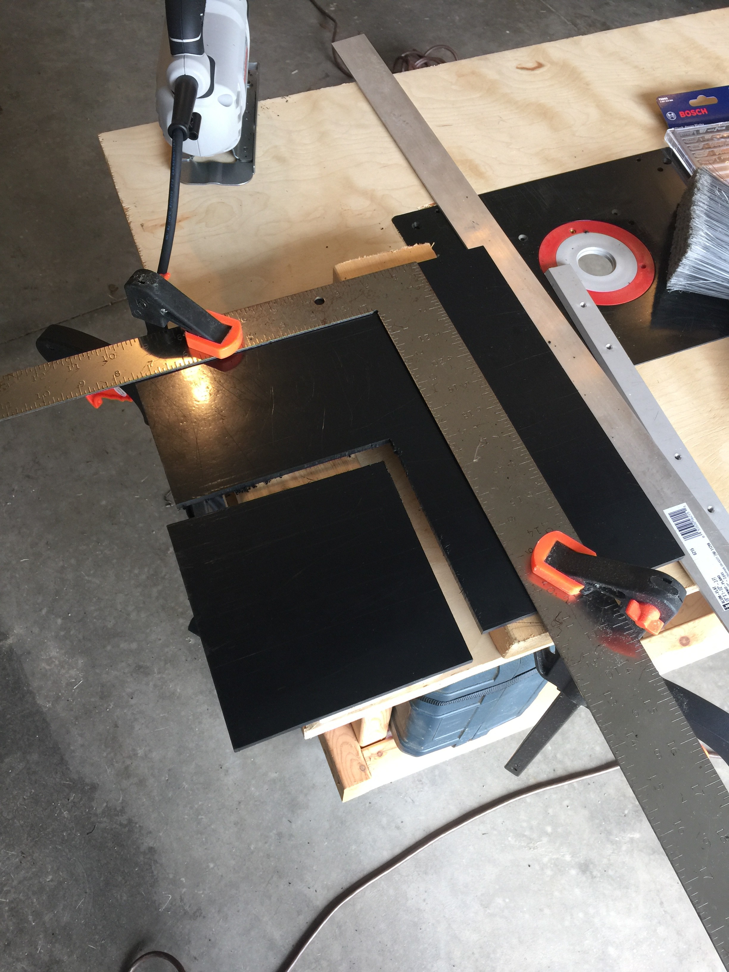
Started cutting the gimbal pieces
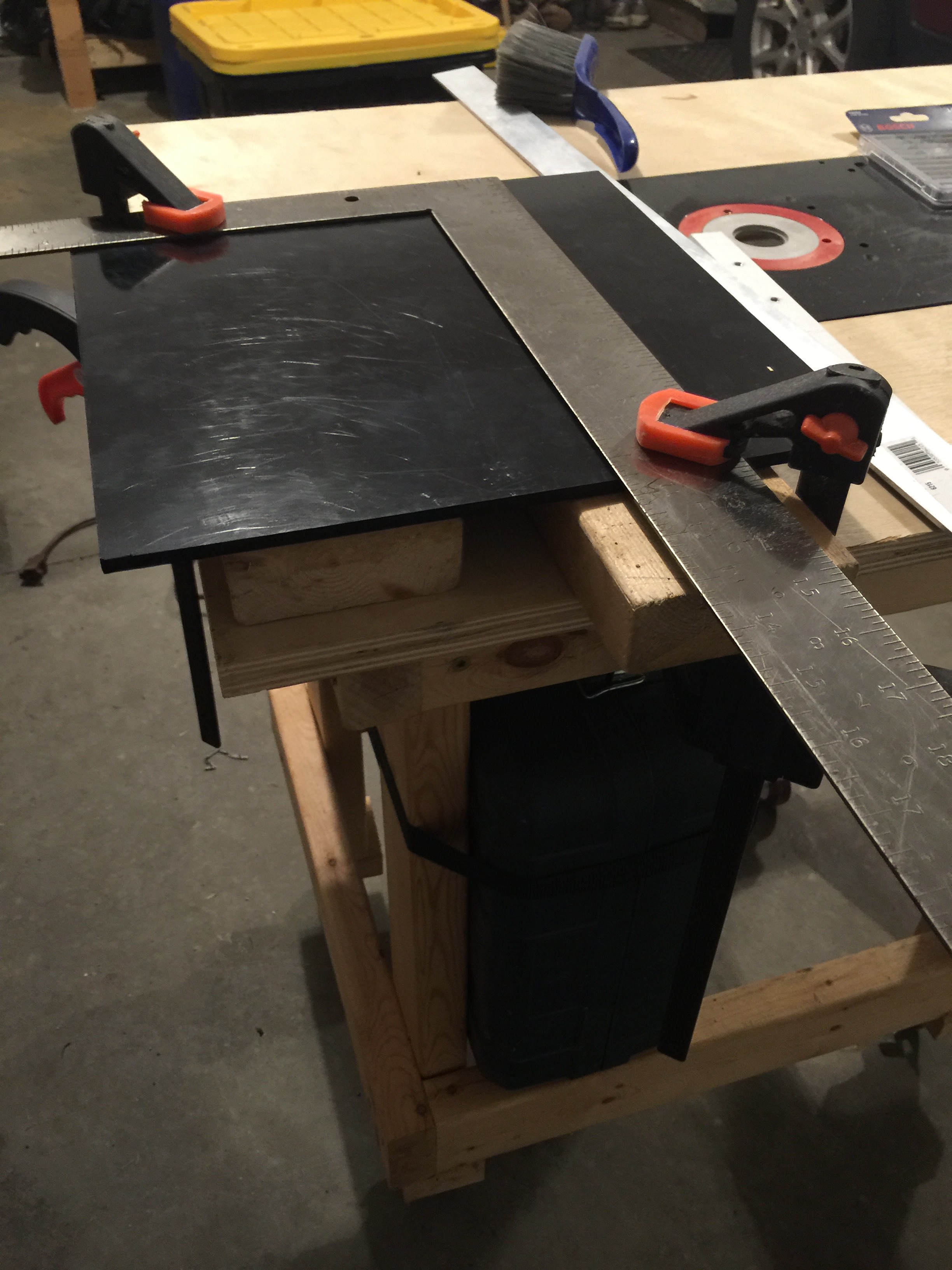
07/05/2016 at 13:51 • 0 commentsStarted cutting my gimbal this weekend, but ran out of time when the wife pointed out that I was going to make everyone late if I finished. (She was right, we were just on time). The big trick to cutting ABS with a jigsaw is to keep the blade cool (I used lots of breaks and flowing air). Small trick is to use a straight edge to keep the lines straight (I used clamps and a straight edge). Oh, and I'm placing the piece on two by fours so that both sides of the plastic are supported in order to decrease vibrations while cutting.
So far I was able to cut the 6" square, 3" square, and two 1" squares. Should speed up for the rest of the pieces now that I've got a method going.
![]()
![]()
![]()
![]()
Open LIDAR
This project is to build a motorized gimbal mount to convert a laser distance module into a 3d LIDAR.