 avishorp
The hammer is assembled from 4 main parts:
- The hammer head.
- The PCB assembly
- End pads (x2)
- Handle
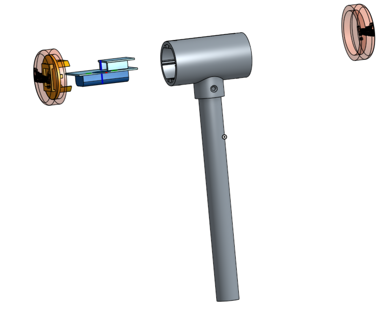
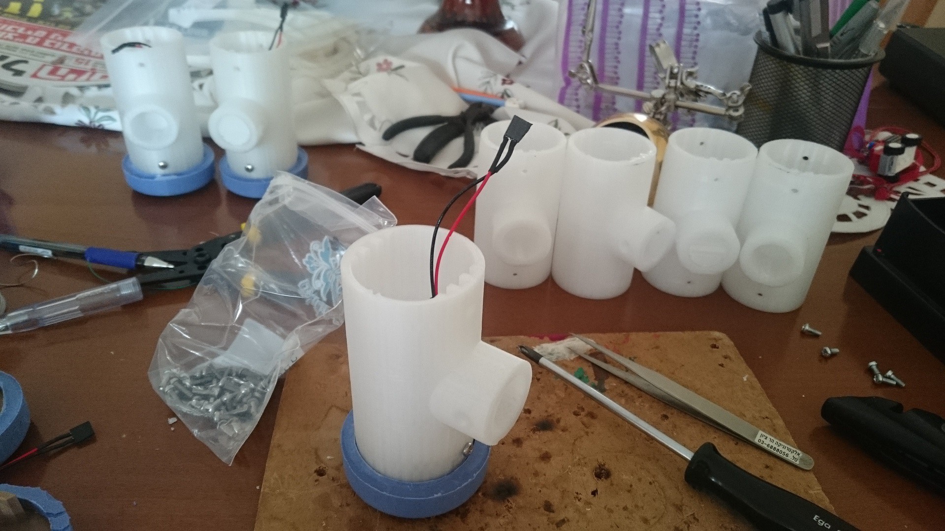
The hammer head is 3D printed. It's designed as a hollow, T-shaped cylinder with rails that hold the PCB and the pads in place. It was printed from transparent ABS which was also acting as a diffuser. The PCB assembly includes the PCB and a 2xAAA battery housing, attached to it using VHB strip.
The most interesting and complex part is the end pads. They include a 3D printed base plate surrounded by potted RTV, which gives its softness. Half of the pads also include a piezo transducer embedded inside the RTV.
The handle is cut from a wooden broom handle.
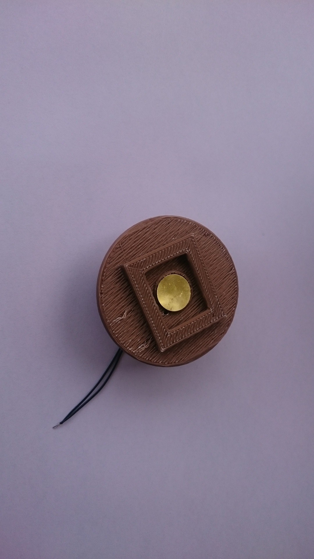
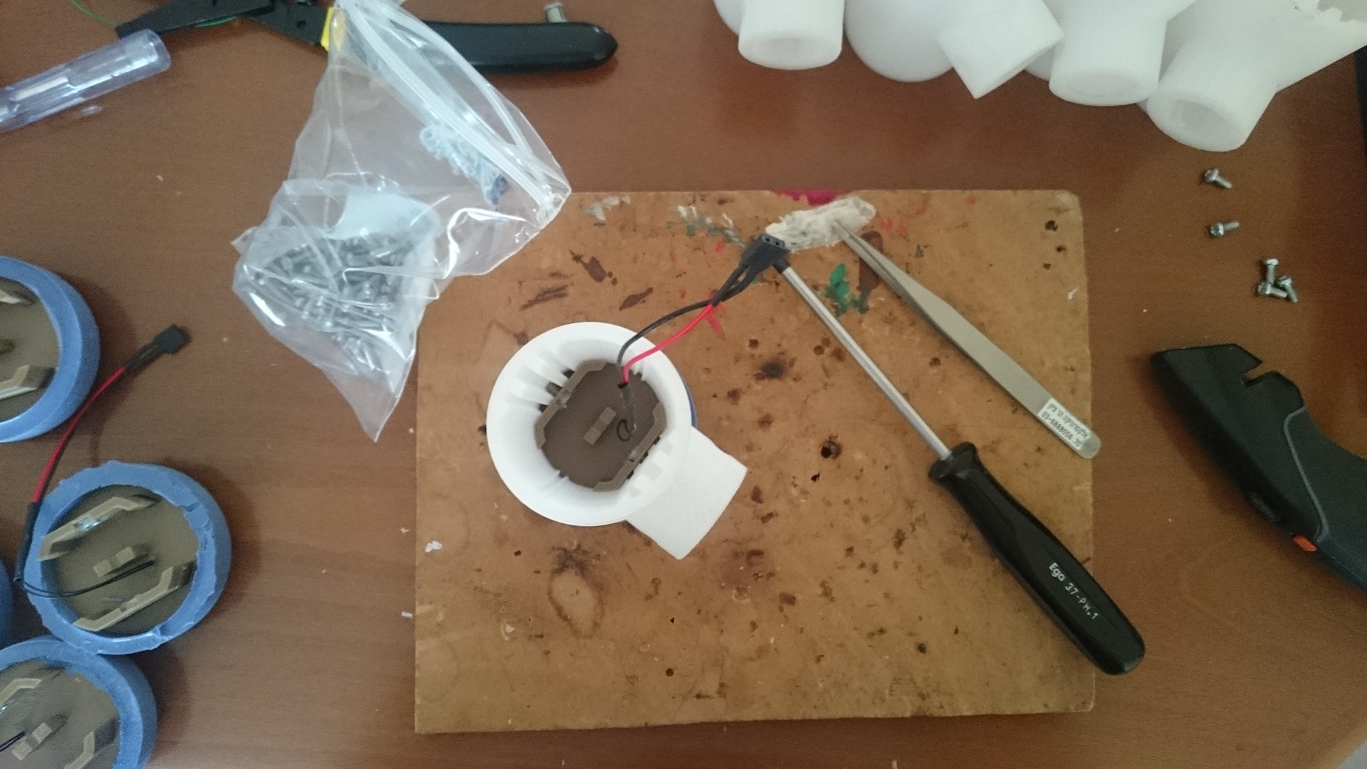
This is the end pad base-plate. It has a place for the piezo sensor assembly, and bridges, under which the RTV would flow and hold to the part.
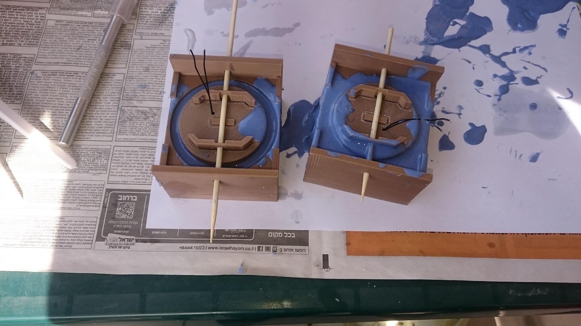
The potting of the RTV. The blue pads indicate that there's a piezo sensor inside, white are inert.
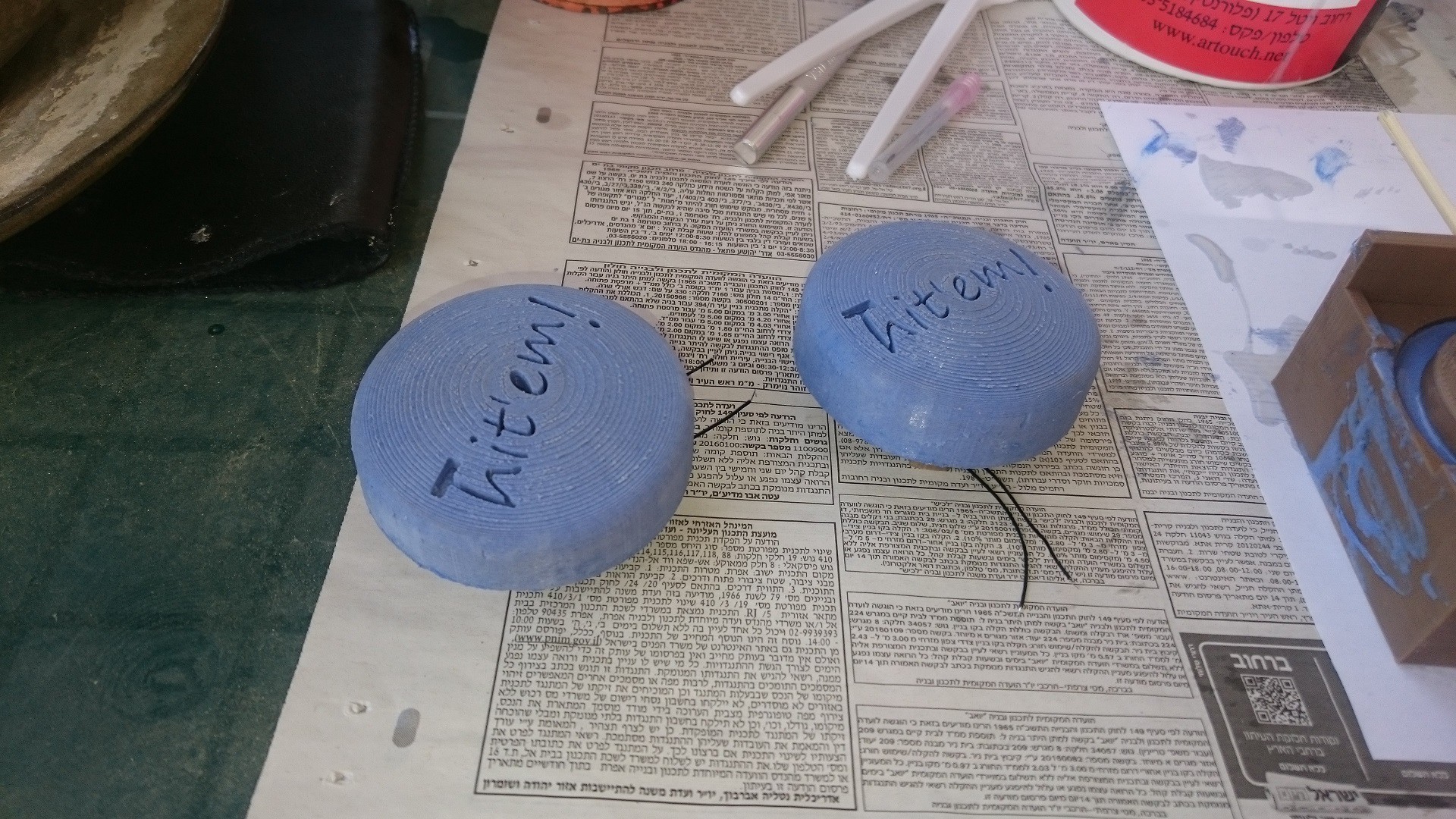
The final end pads.
Assembly of the hammers
And here's he final product:

Discussions
Become a Hackaday.io Member
Create an account to leave a comment. Already have an account? Log In.