Time Domain
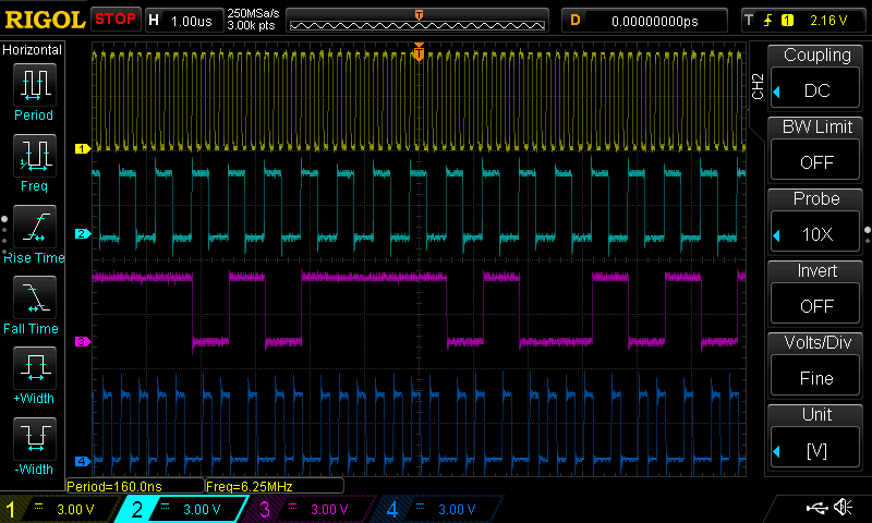
To verify the operation of the DDL04, I first looked at the signals in the time domain:

The traces are as follows:
- (yellow) : 6MHz clock input
- (cyan): Divider output (set to "2")
- (magenta): LFSR output (pseudo-noise bit stream)
- (blue): Spread-spectrum output
Everything seems reasonable here. The bandwidth divisior is set to 2, so the divisor output is the base clock / 4 (there's always a fixed 2x divisor). The pseudo-noise looks pseudo-noisy, and the output certainly looks modulated by it, but the time domain isn't the best place to analyze the output signal.
Frequency Domain
To examine the signals in the frequency domian, the output was connected to a spectrum analyzer through a 20dB external attenuator. Just in case. Nothing ruins your week like blowing the first mixer in your SA (trust me). At least this one beeps when it's over-driven.
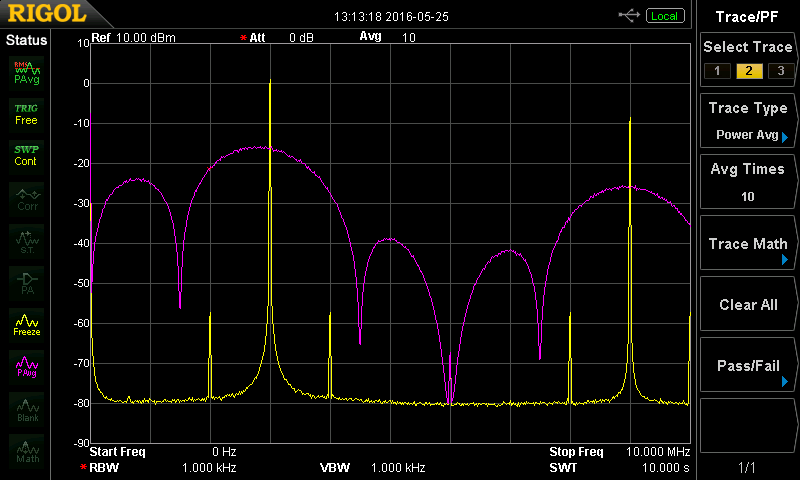
In the image below, the yellow trace is the non-spread signal (fundamental at 3MHz). The approximately -60 dBm sidebands at +/- 1 MHz are spurs from the DDS generator I used to drive the board at 6 MHz. The magenta trace is the output of the board spread with a 2-divider (+/- 1.5MHz at first zeros). Seems like it's working.

There's an important note about this kind of comparison. It would be tempting to compare the peaks at 3 MHz and conclude that the spreading has reduced possible interference by about 15 dB. While this kind of analysis works for narrow-band signals, noise (even pseudo-noise) is a different animal. The measured amplitude of a noise signal depends on the measurement bandwidth: in these plots, the analyzer has been set to a resolution bandwidth of 1 kHz. Measuring using a wider bandwidth will move the magenta curve upward; a narrower bandwidth will move it down. Likewise, in a receiver, the amount of interference received will depend on the reception bandwidth.
Another point of interest. Although the curve appears continuous, it is actually composed of 32767 individual spikes, in this case spaced at 1.5 MHz / 32767 = 45.8 Hz. The narrowest RBW on this particular analyzer is 100 Hz, so it can't resolve these spikes.
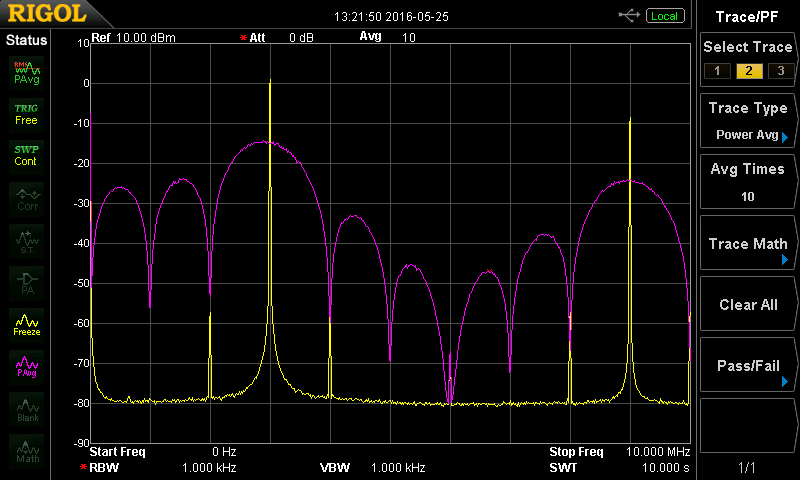
Here's the same image with the divider set to 3 (3 +/- 1 MHz inside the central lobe). This is the setting that seems to work best with the clock as-built. I would have liked to use the widest bandwidth setting, but the DDL gates don't perform as well with the lower-frequency energy in that signal. I suspect the ideal approach is to use maybe a 9 MHz clock with the 2-divisor, yielding a 4.5 +/- 2.25 main lobe, but I haven't had time to do an in-depth analysis.

For completeness, here's the output with the divisor cranked all the way to 10 (yes, I did think about having it go to 11, but it's not easy using a '4017). This is a pretty narrow bandwidth, and is probably only useful for diode gates using tuned circuits, quarter-wave lines, or other narrow-band structures.

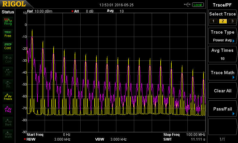
Finally, a quick look further up the spectrum (here to 100 MHz) shows what we'd expect - the fast edge rates on the 74AC244 contain strong harmonics into the VHF region. Of course, at the output of the the board, this signal is still just logic-level (and inside coax) so there's not too much concern. Additionally, filtering it here would be pointless; the DDL02 will just restore the hard edges and the corresponding harmonics (it is by no means a linear amplifier). In the sequel, I'll measure the power supply system end-to-end.

Next: Puzzling measurements and 4-40 threaded standoffs as inductors.
 Ted Yapo
Discussions
Become a Hackaday.io Member
Create an account to leave a comment. Already have an account? Log In.