 Camilo Parra Palacio
-
1Step 1
![]()
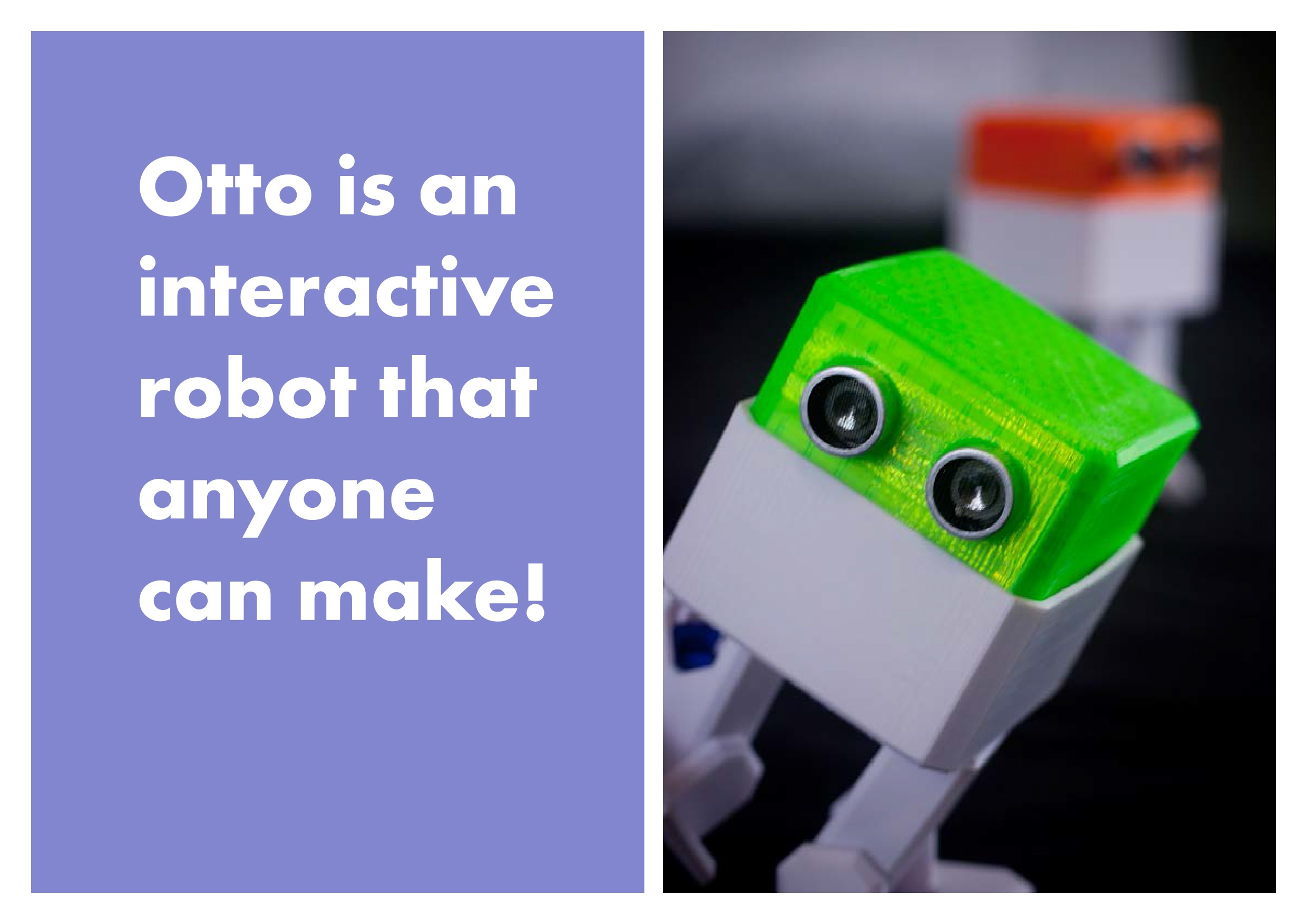
Who is Otto?
An interactive robot that anyone can make!
![]()
What can Otto do?
Otto walks, dances, makes sounds and avoids obstacles.
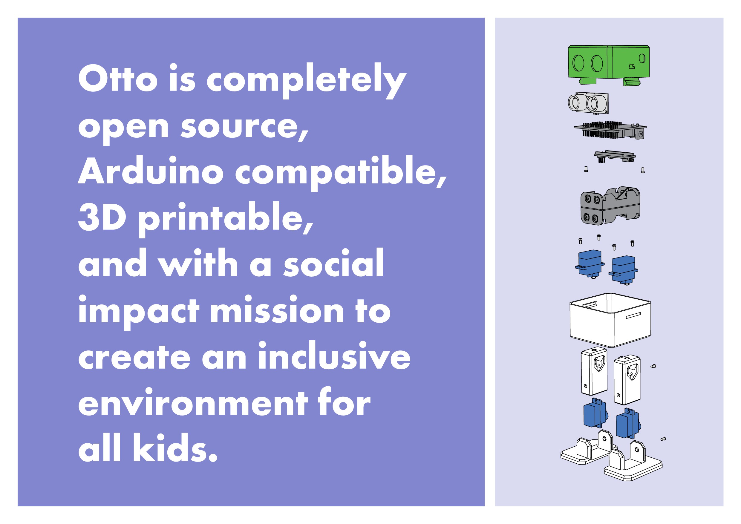
Why Is Otto special?
Otto is completely open source, Arduino compatible, 3D printable, and with a social impact mission to create an inclusive environment for all kids.
Otto was inspired by another robot instructable BoB the BiPed and programmed using code from another open source biped robot called Zowi.
CC-BY-SA
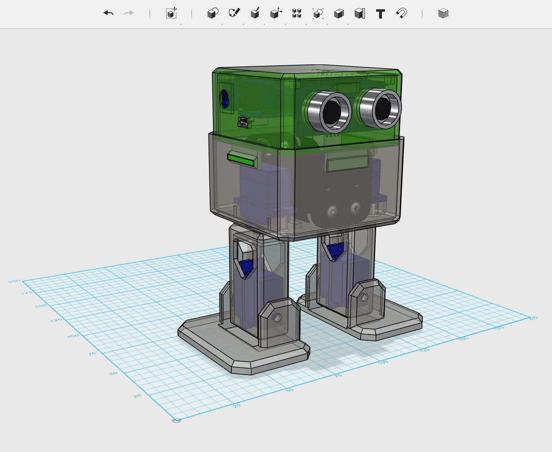
Otto's differences are in the assembled size (11cm x 7cm x12cm), cleaner integration of components and expressions. Using off the shelf and 3D printed parts, simple electronics connections (almost no welding required), and basic coding skills, you will be able to build your own cute Otto friend in as little as two hours!
Otto is design using Autodesk 123D Design software you can modify it for customization or further improvements!
![]()
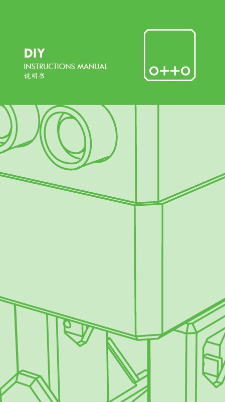
This instructable focuses on how to build the Otto DIY version - yes, more Ottos are coming and you can stay tuned for updates by subscribing on ottodiy.com
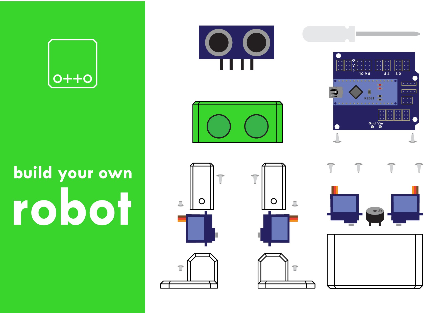
Step 1: First gather all parts and tools
![]()
Gather all the off the shelf parts that you'll need for this assembly. Here's the list:
1. Arduino Nano; preferable with the pins already weld it
2. Arduino NANO Shield I/O Extension Board Expansion XD-212
3. Mini usb cable. (most Arduino dealers provide the cable)
5. Mini servo SG90 9g x4 (each one should come with 2 pointed screws and one small screw).
6. 5V Buzzer.
7. Female to Female breadboard connectors cable 10cm x6.
9. 1.5V AA batteries x4.
10. Mini cross screwdriver. important magnetized
And then you only need to 3D print 6 parts in total:
11. 3D printed head.
12. 3D printed body.
13. 3D printed leg x2.
14. 3D printed right foot.
15. 3D printed left foot.
Optional: cutter for post cleaning the 3d parts (if the 3d print quality is good enough no need) and a soldering iron (if you want it battery power otherwise can still connect it through usb to energize)
![]()
That's all simple!; Download all .stl files, If you do not have a 3d printer you can always use services like 3dhubs.com or local maker spaces.
If you think is difficult to find the parts, go to www.ottodiy.com to buy robots kits.
-
2Step 2
Step 2: 3D print settings
![]()
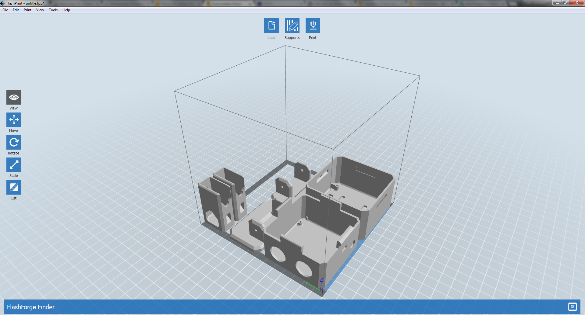
Otto is very well designed for 3D printing, the files that you had downloaded are property oriented and centered, so wont give you trouble if you follow this common parameters:
- Recommended to use a FDM 3D printer with PLA material.
- No need supports or rafts at all.
- Resolution: 0.15mm
- Fill density 20%
You can print individually piece by piece to match the colors of the original design or optionally print all at the same time in an area of 14cm x 14cm.
For slicing and generating the g code for the machine free slicer software like Cura or in our case FlashPrint that comes with the FlashForge Finder 3D printer that we are using (If you are outsourcing the printing no need to worry about it)
After printing you will need to clean a little bit the legs and feet areas that fix the motors.
![]()
-
3Step 3
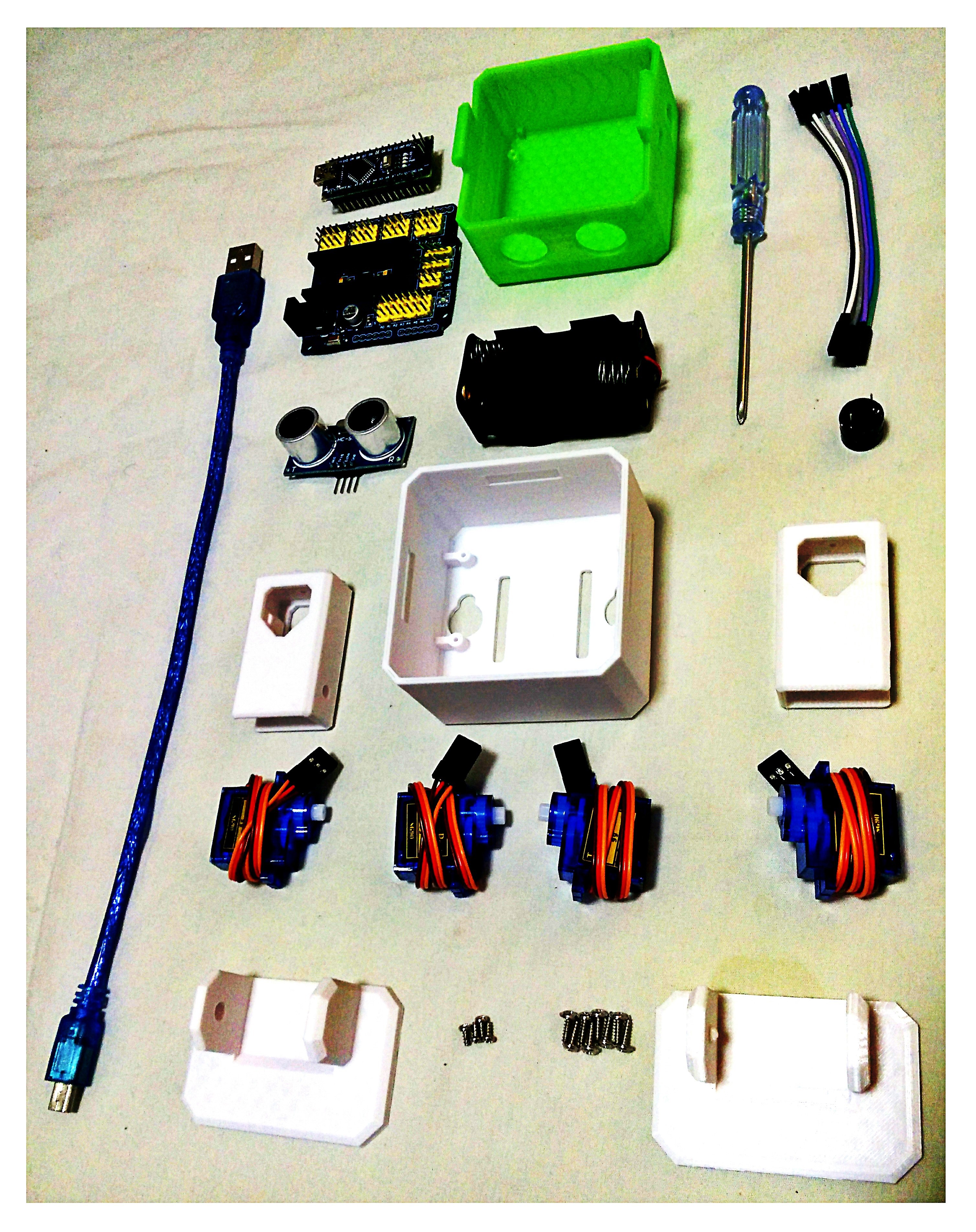
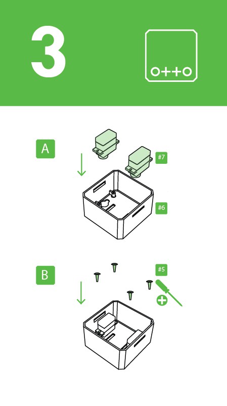
Step 3: Reorganize & check your parts from bottom to top.
![]()
![]()
As mention in step 2, Micro servo motors come with 3 screws in the picture are now included and rearranged the parts number for easy reading.
Remember to have ready your magnetized mini screwdriver.
-
4Step 4
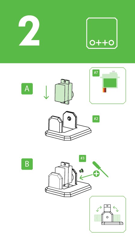
Step 4: Foot servos assembly
![]()
![]()
Put the micro servo inside feet and then push it inside, if is to hard maybe need to clean more the area with a cutter.
Is very important to check that the servo is able to rotate at least 90 degrees to each side.
After checking the movement use only the small screw to fix it.
Same process for the other foot.
![]()
-
5Step 5
![]()
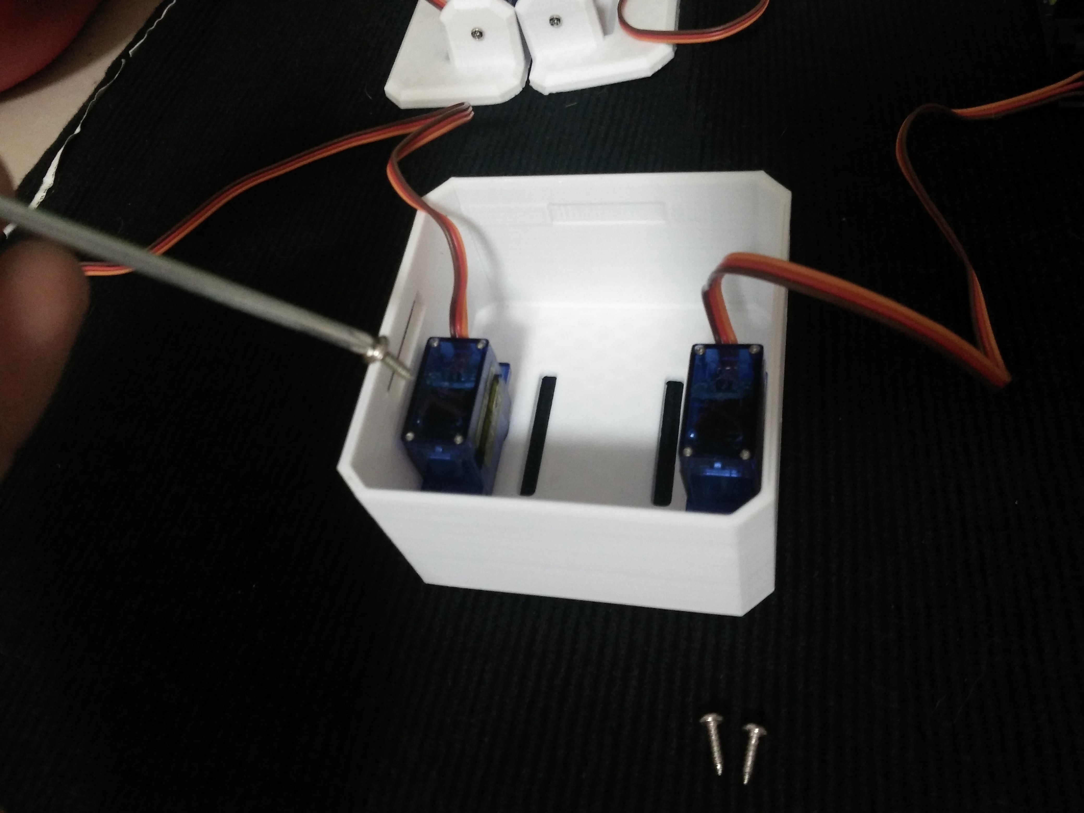
Step 5: Fix Servos to Body
![]()
Take the other 2 micro servos put them in the defined locations in the 3D printed body and fix them only with the pointed screws.
-
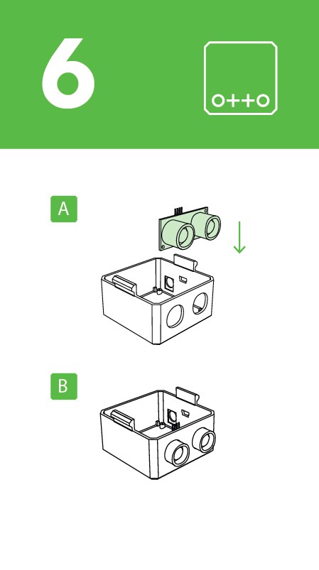
6Step 6
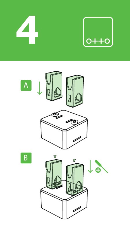
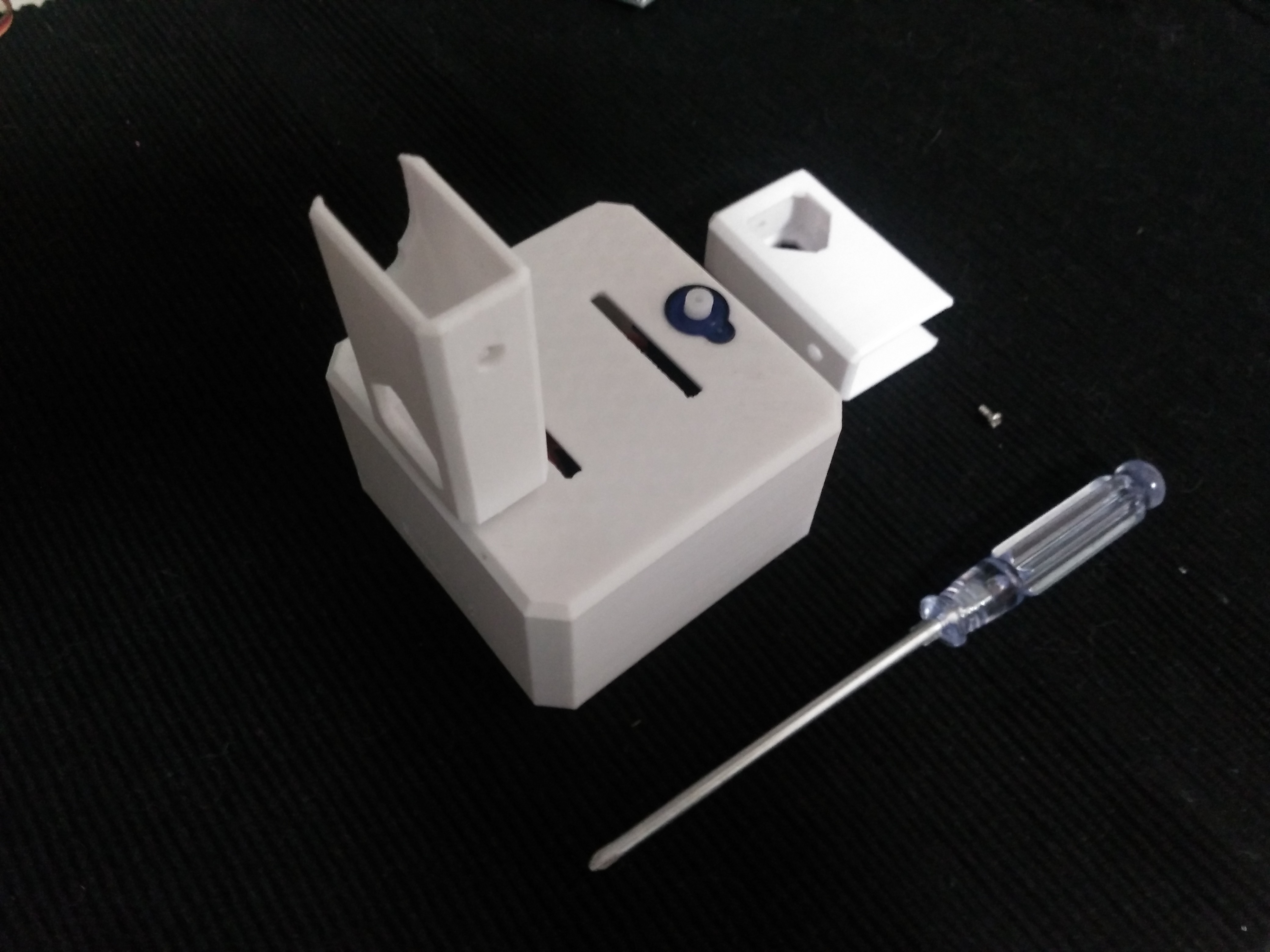
Step 6: Fix Legs to Body
![]()
![]()
Connect the legs to the hub of the micro servo, important like the foot servos you must check the legs are able to rotate 90 degrees each side respect to the body.
After verifying the alignment fix them using the small screws to the hole inside the leg.
-
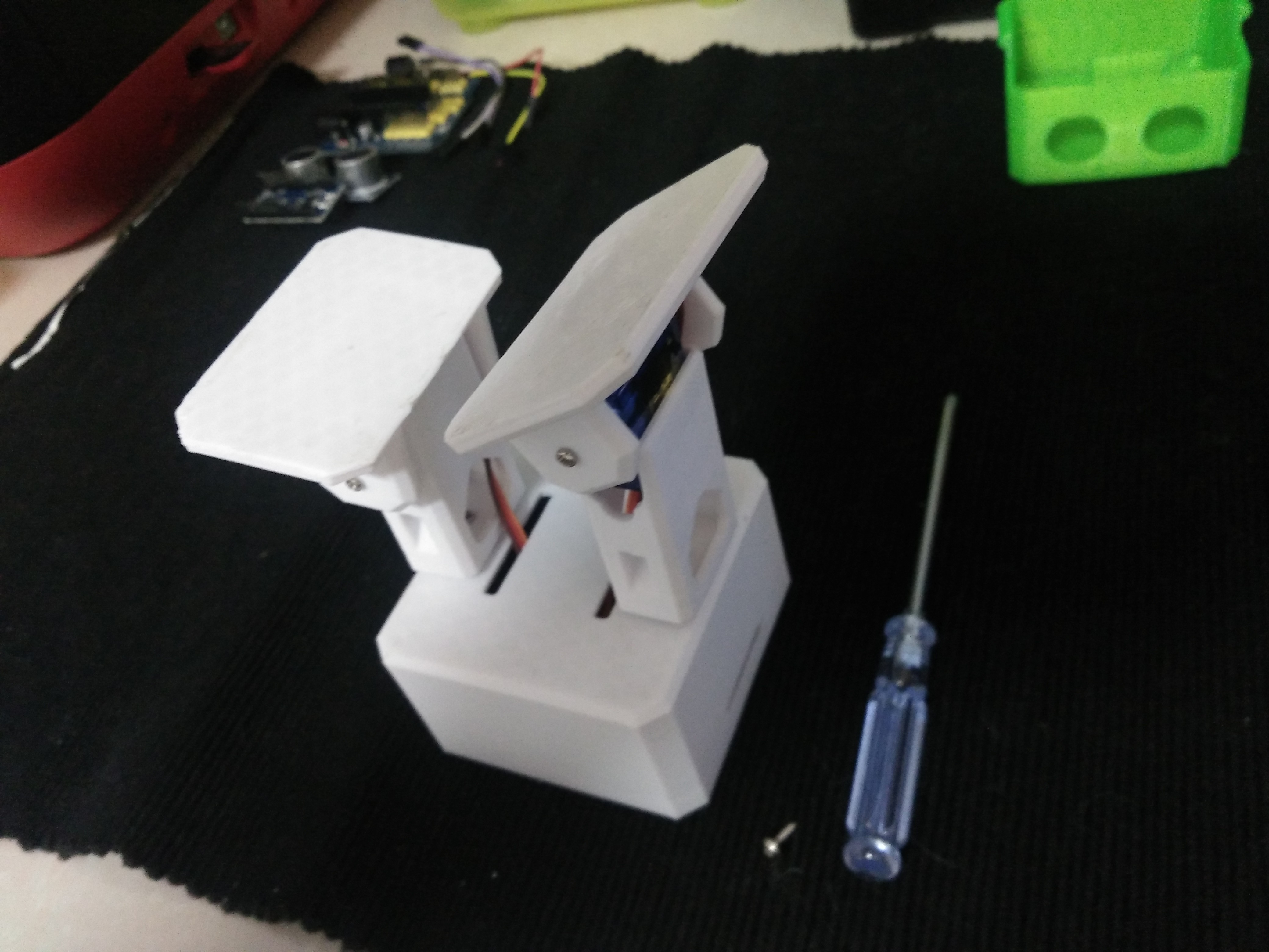
7Step 7
Step 7: Fix Foot to Legs
![]()
![]()
Taking care of the cables as showed in the illustration you should put the cables inside the slots of the body passing thought the hole of the legs.
Once they are in right position use the pointed screws to fix them from the back.
-
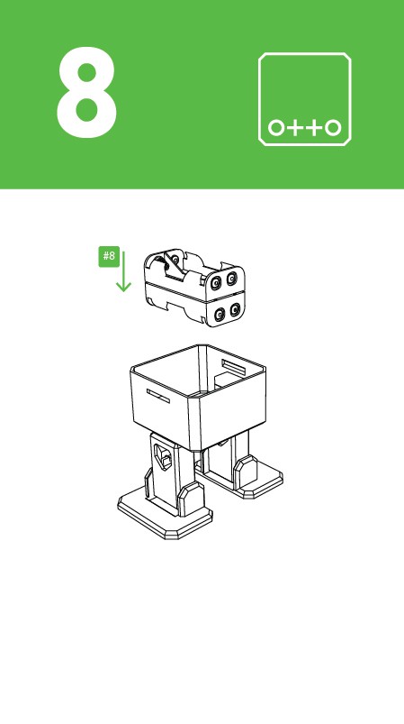
8Step 8
![]()
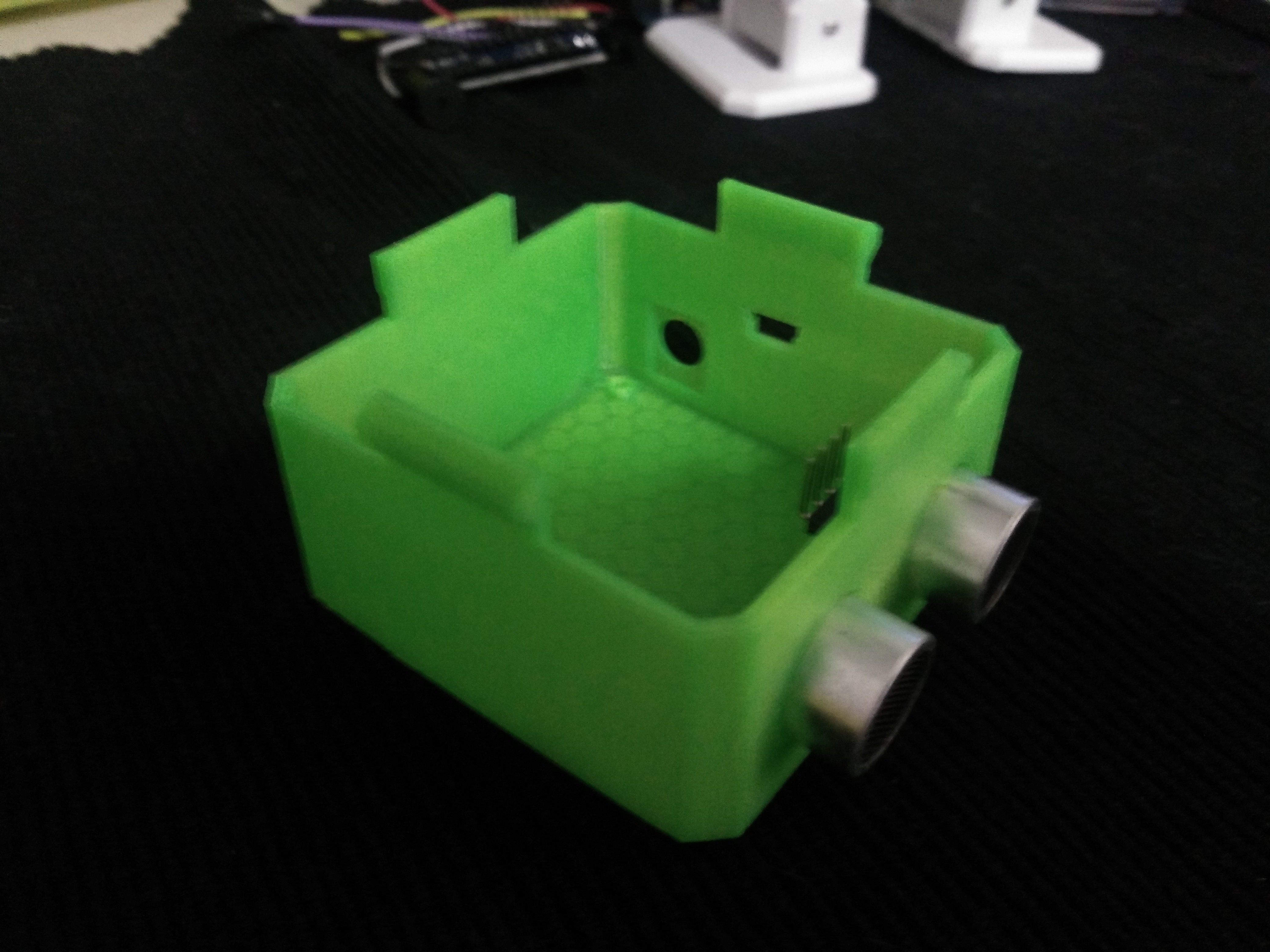
Step 8: Head assembly
![]()
![]()
![]()
![]()
![]()
Start from the ultrasound sensor is important to pull out the eyes to the limit.
After putting the Arduino nano in the shield, optionally you can weld the battery holder positive cable to Vin in the board and negative to any GND.
Insert diagonally the both boards together facing the USB conector to the hole in the 3D printed head, then use the last 2 pointed screws to fix it.
-
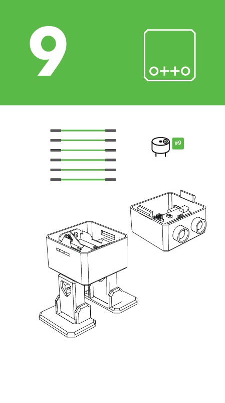
9Step 9
Step 9: Electric connection
![]() Prepare the breadboard cables and buzzer.
Prepare the breadboard cables and buzzer.Then follow the diagram pins numbers and make sure to put them in the right position.
-
10Step 10
Step 9: Electric connection
![]()
![]()
Prepare the breadboard cables and buzzer.
Then follow the diagram pins numbers and make sure to put them in the right position.


 Prepare the breadboard cables and buzzer.
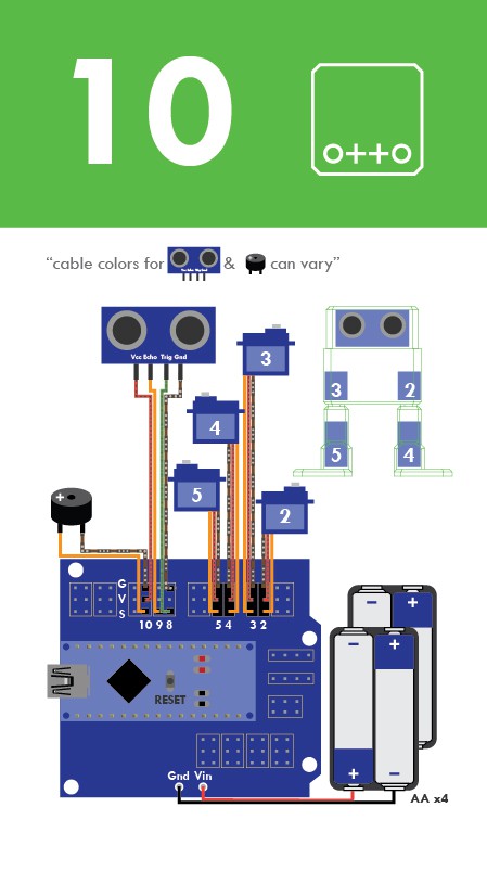
Discussions
Become a Hackaday.io Member
Create an account to leave a comment. Already have an account? Log In.