This log details the Hardware preperations required for building the MyComm device using the off-the-shelf parts for Prototype 1.
Hardware Preperation:
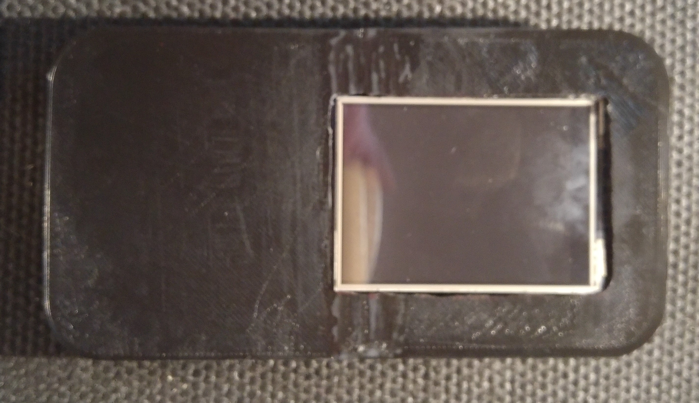
3d Print the case parts: Case Design - Front Cover Screen - RockBlock V0.1.stl, Case Design - Base V0.1 - Rockblock Support.stl
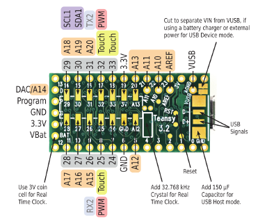
The stock Teensy 3.2 connects Vin with VUSB. This means that the Teensy can't be powered by Battery and re-programmed at the same time. If you want to be able to reprogramme the Teensy under battery power you either need to cut the 5V line on a usb cable or cut the Vin-VUSB trace on the underside of the Teensy:
Veroboard Build:
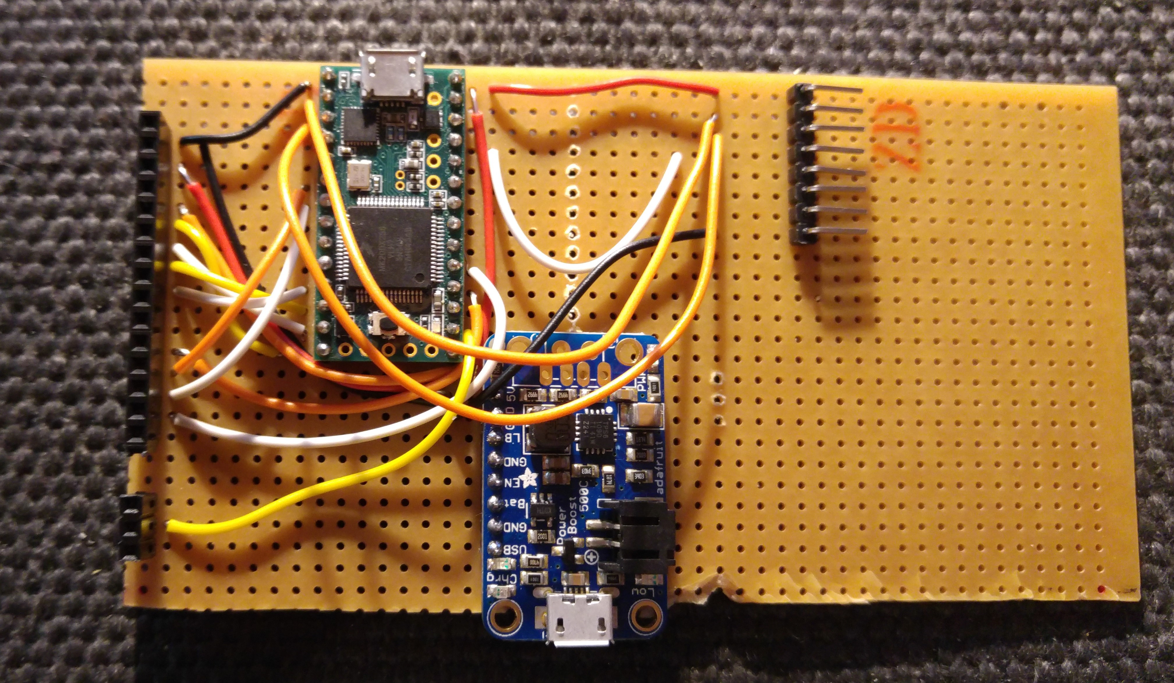
Follow the wiring schematics in order to build a veroboard to attach devices. This is my first run at building the MyComm prototype so there may be easier ways to achieve the build but this is the documentation first build;
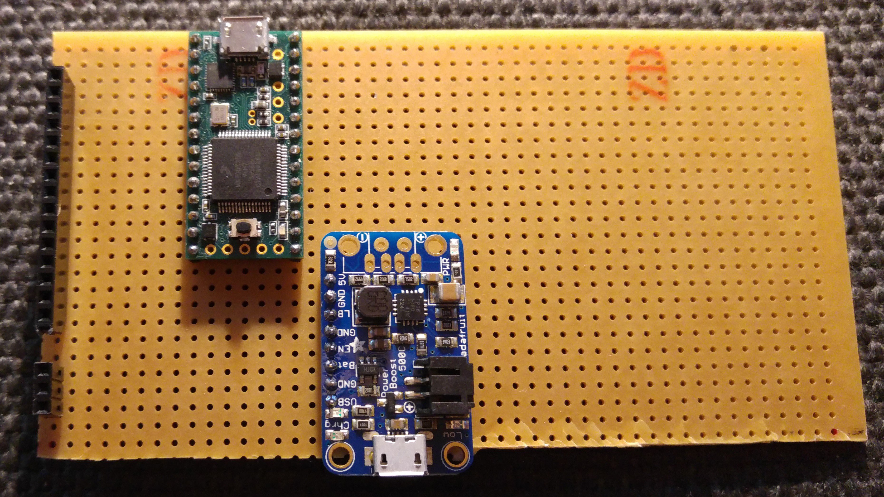
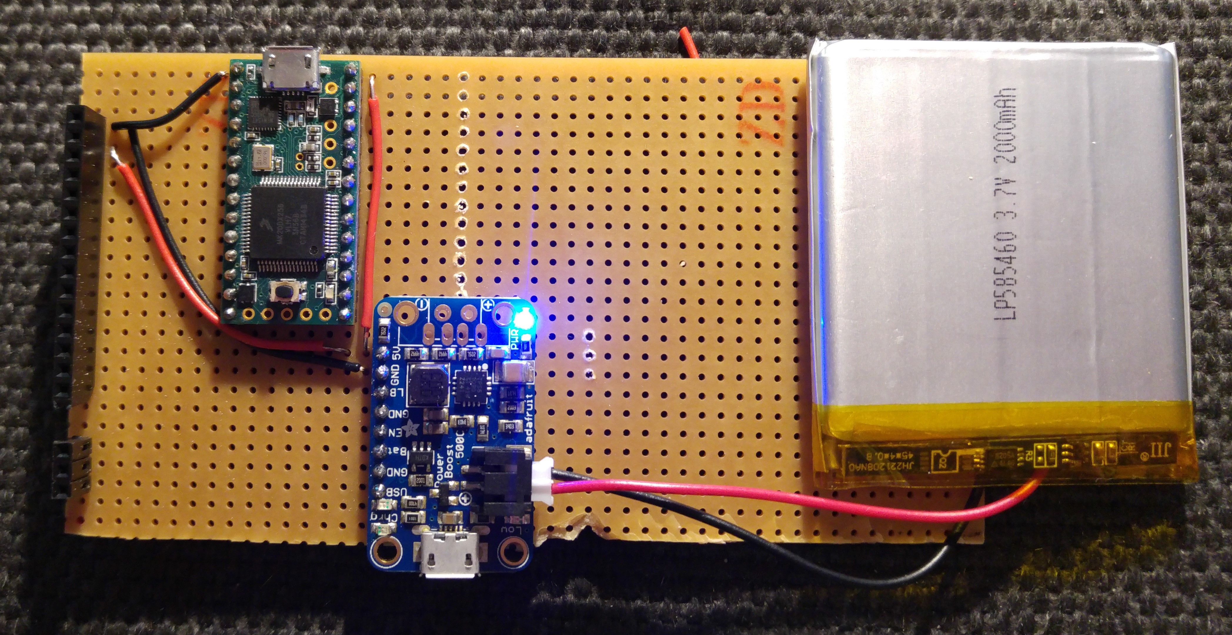
- Step 1: Lay out the Teensy, Headers for the Screen and Charging Circuit.

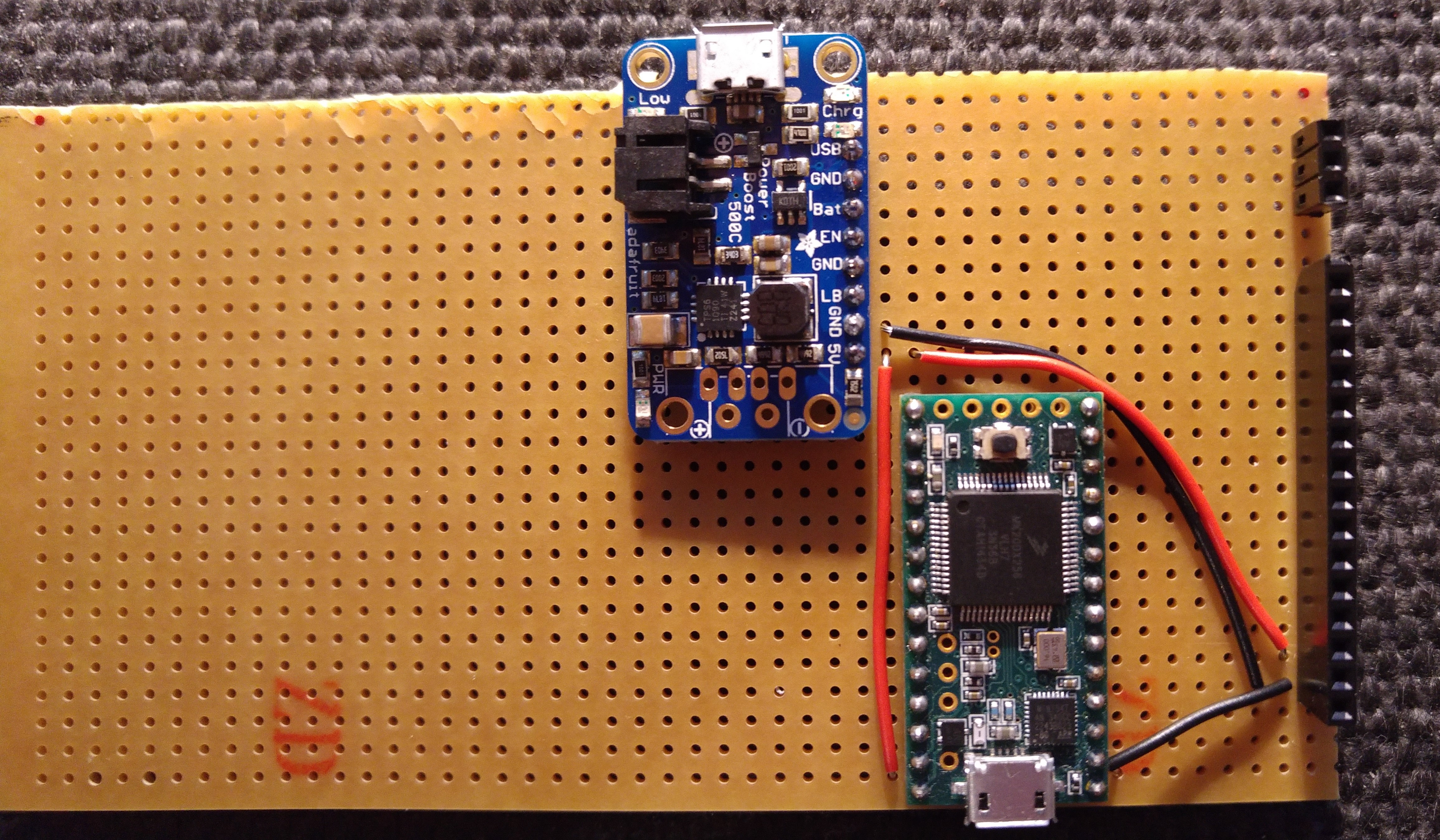
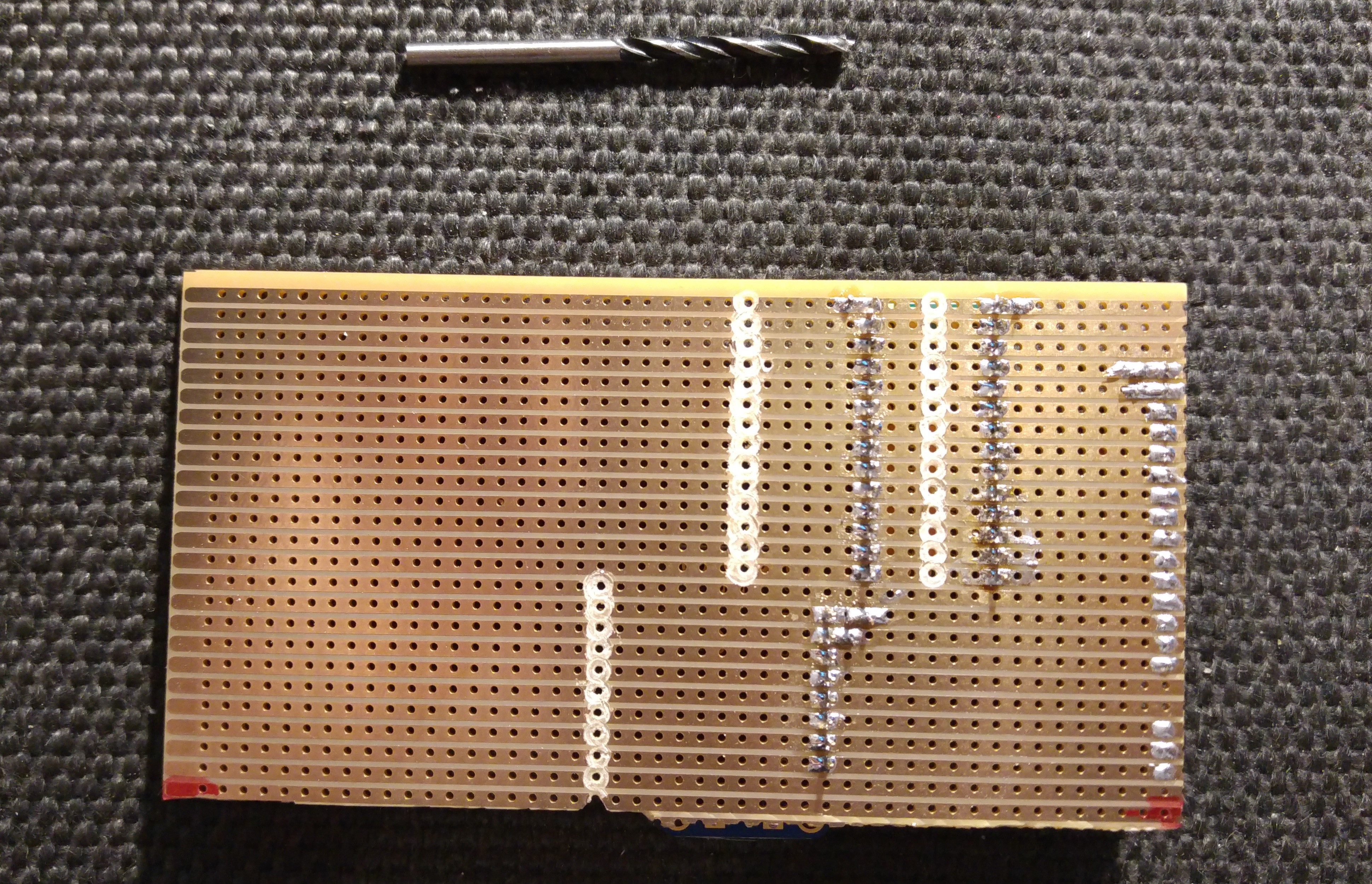
- Step 2: Layout and solder power connections for the 5v Output. I find the easiest way to break the veroboard column connections is with a medium size drill bit in my hand drill.
- Step 3: Test battery power with the Teensy. If you've completed Build (1) then the Teensy LED should blink steadily with the battery connected. If not, check all wiring before trying to connect the Teensy to the PC.
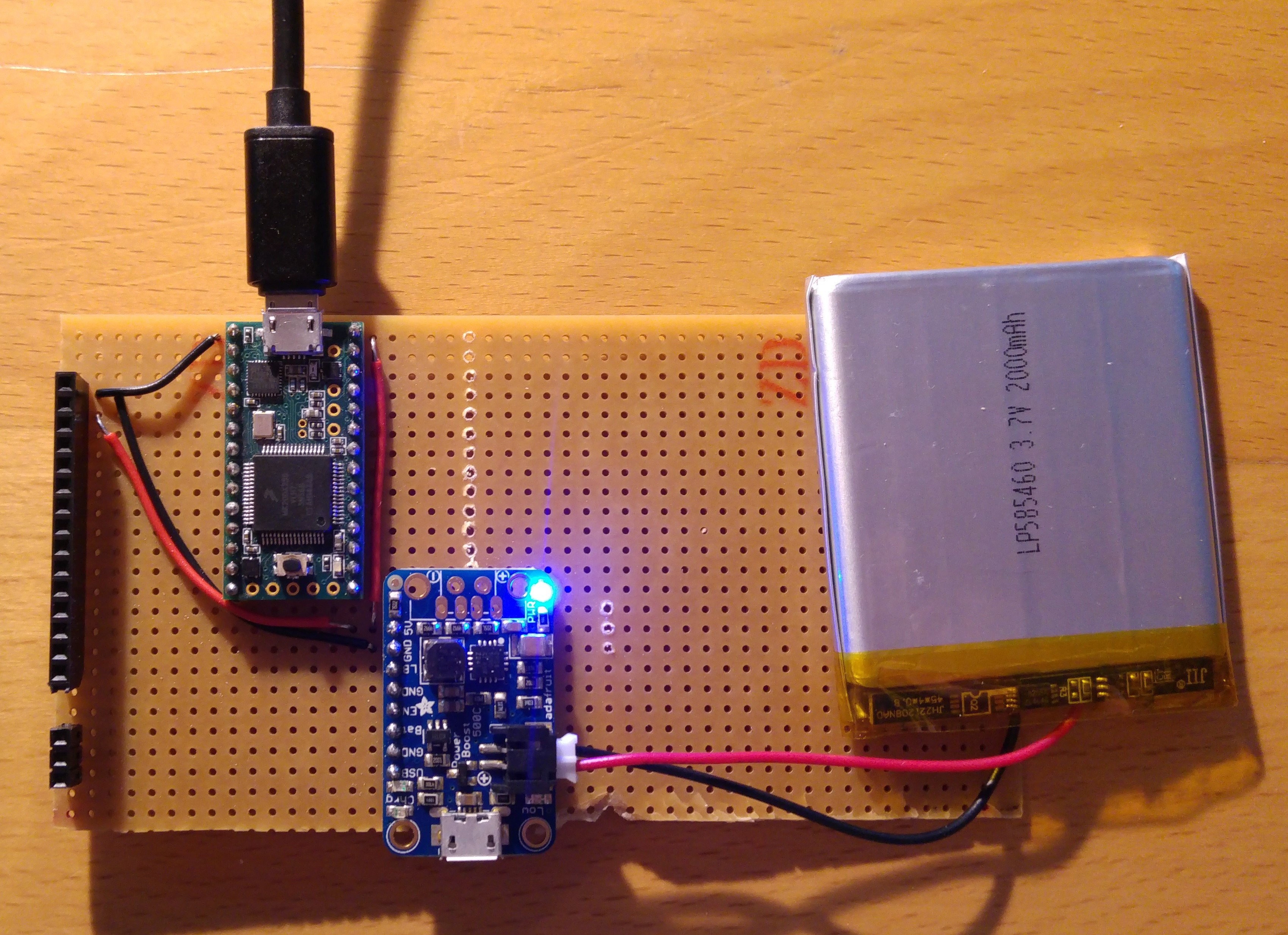
- Step 4: Reprogram the Teensy with the MyComm code (Ensure your Vin-VUSB connection has been cut!). See Build(1) for further details.
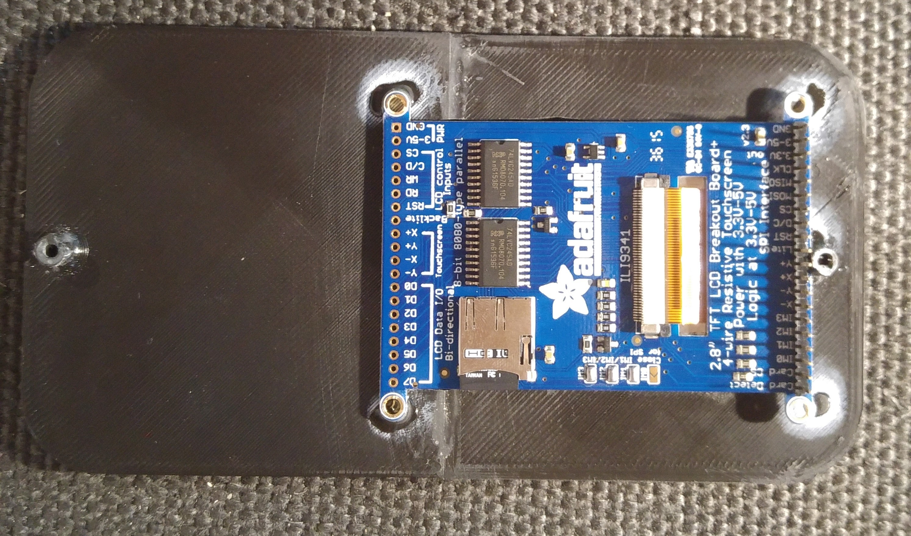
- Step 5: Lay out the wiring for the SPI to the screen/SD

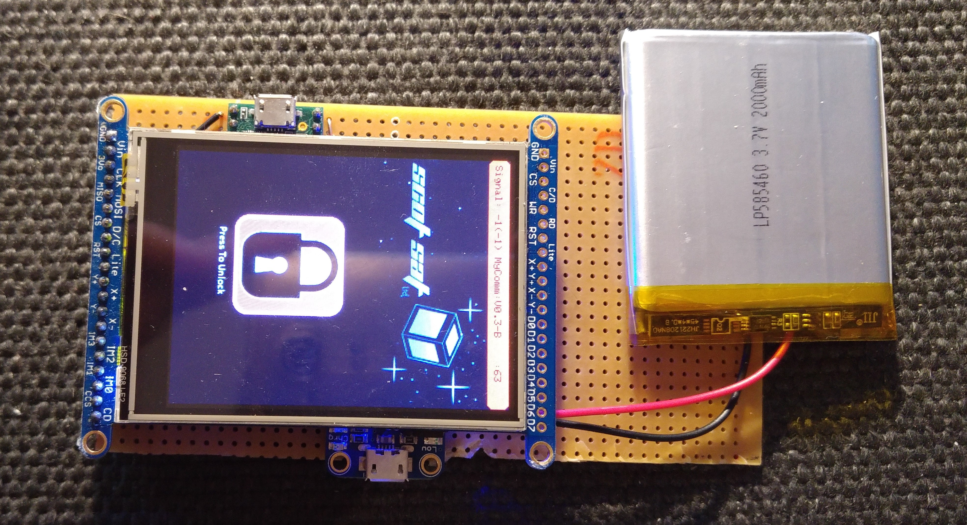
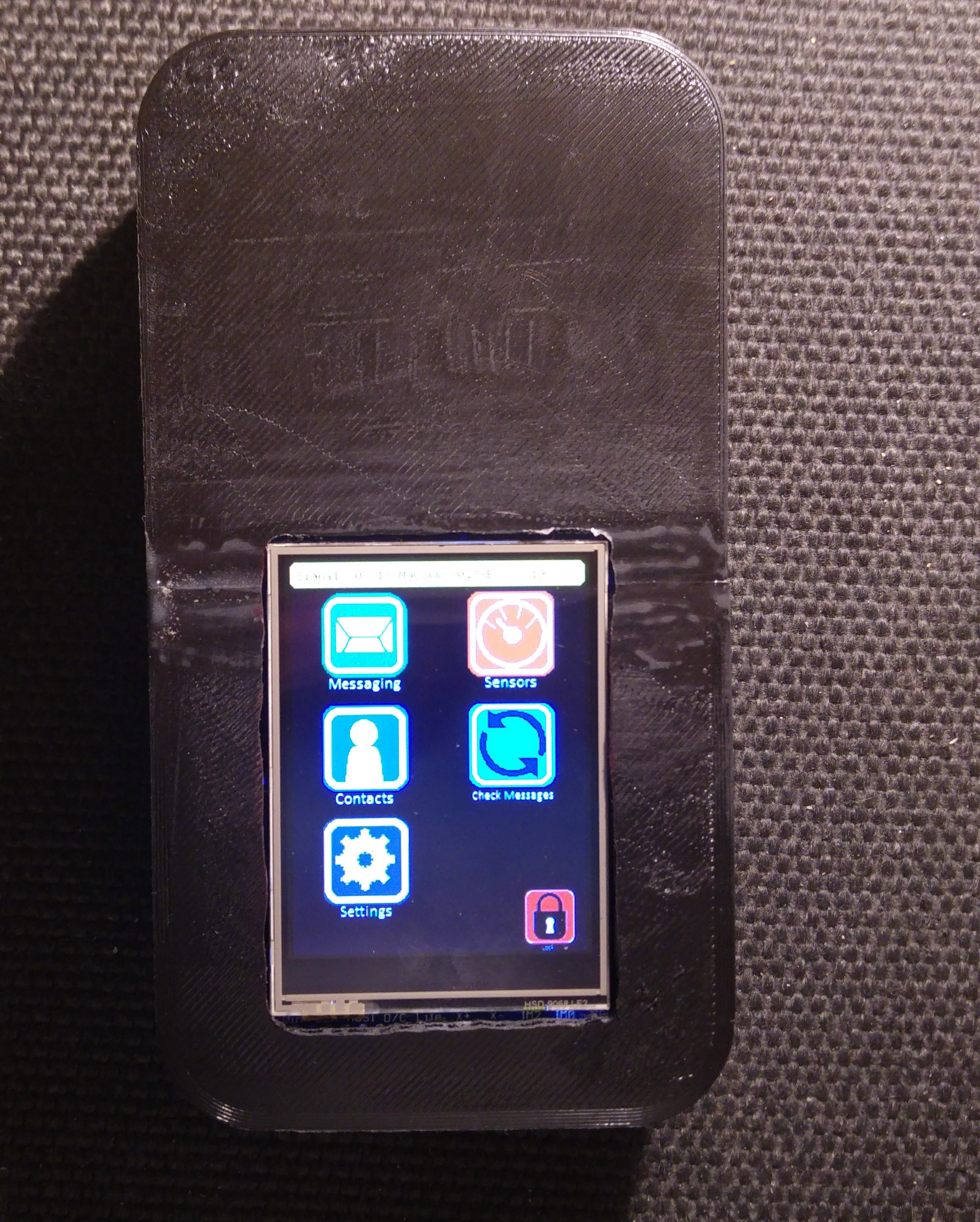
- Step 6: Insert your blank SD card into the slot on the back of the screen then test the screen with the battery connected. You should see the MyComm interface.
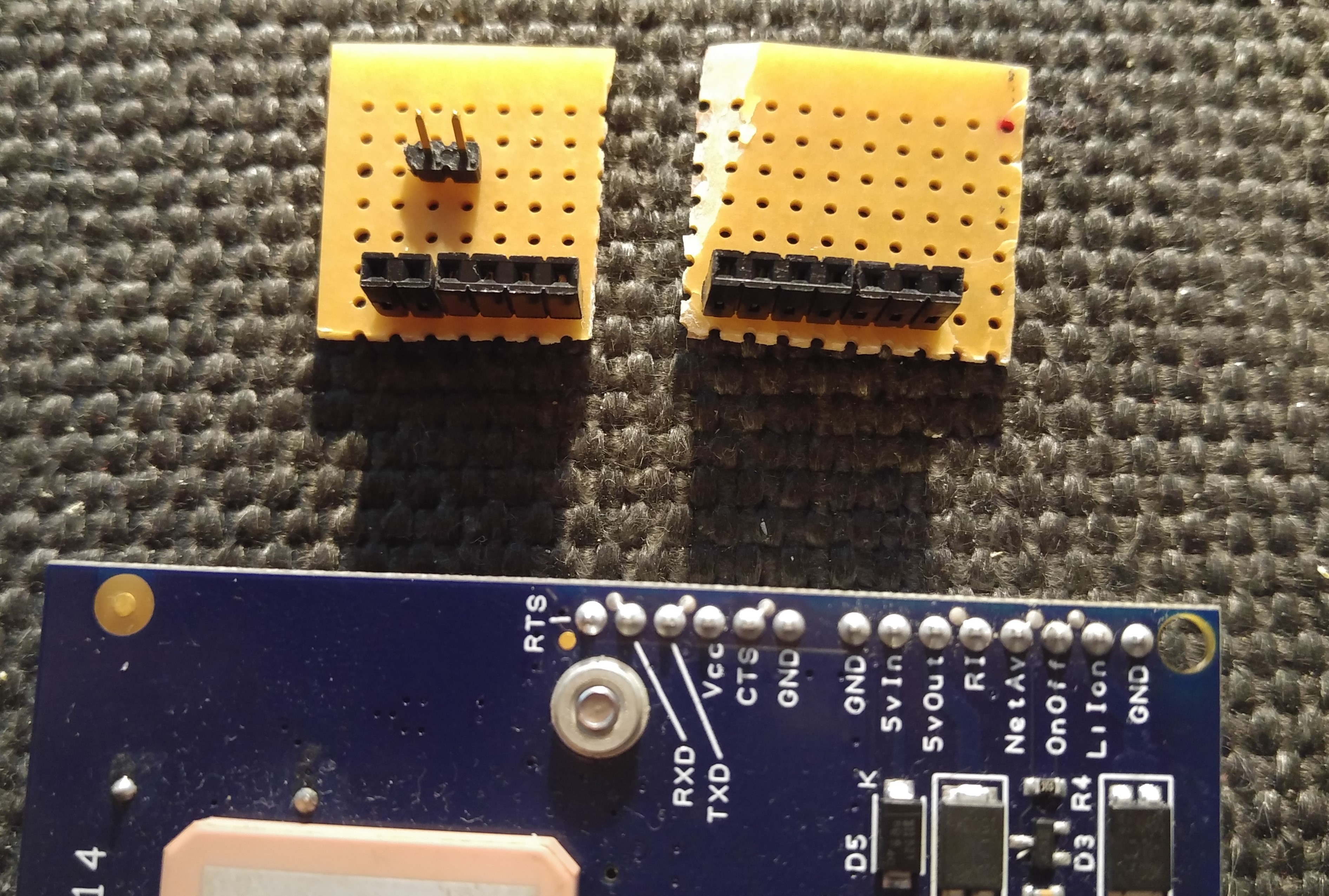
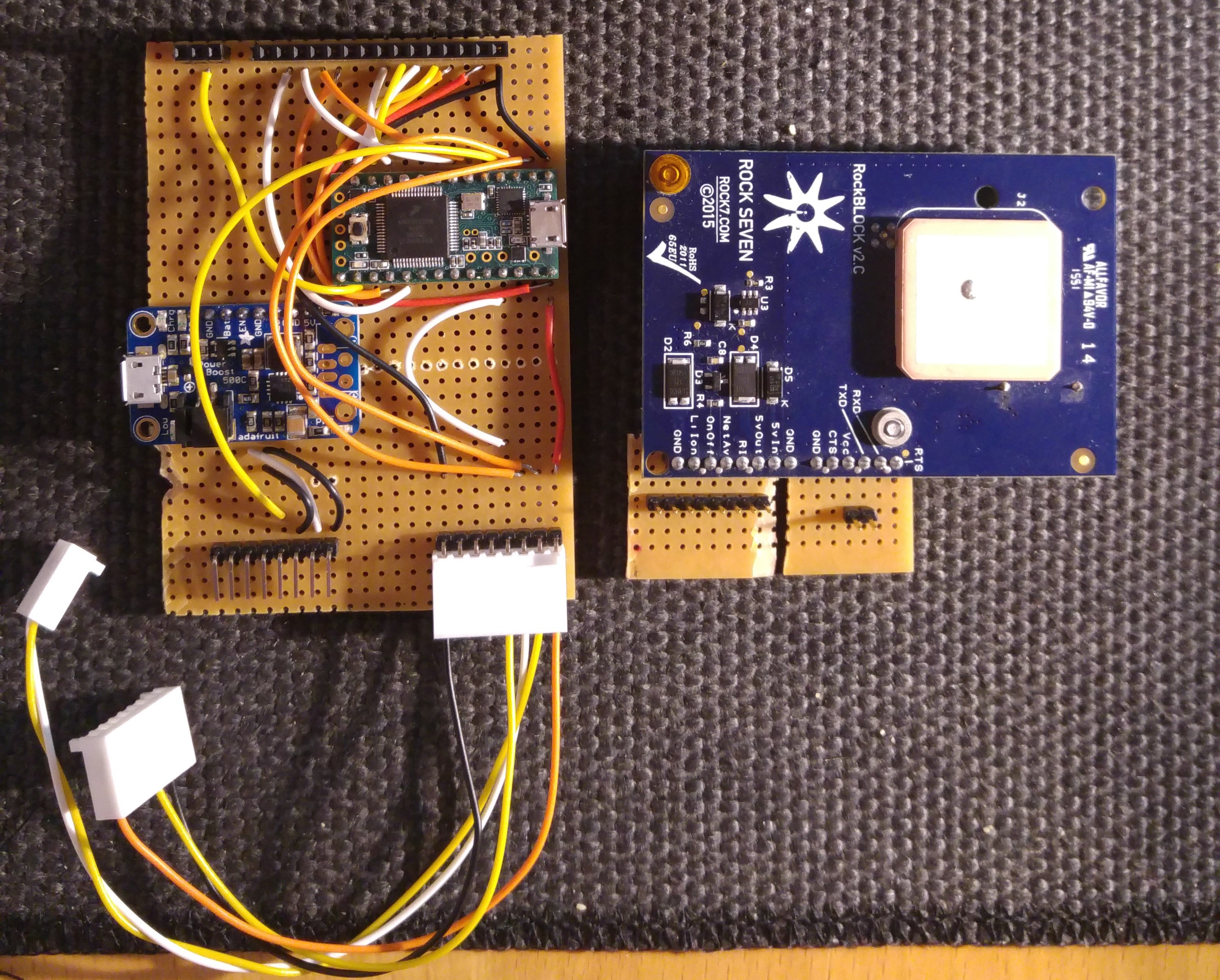
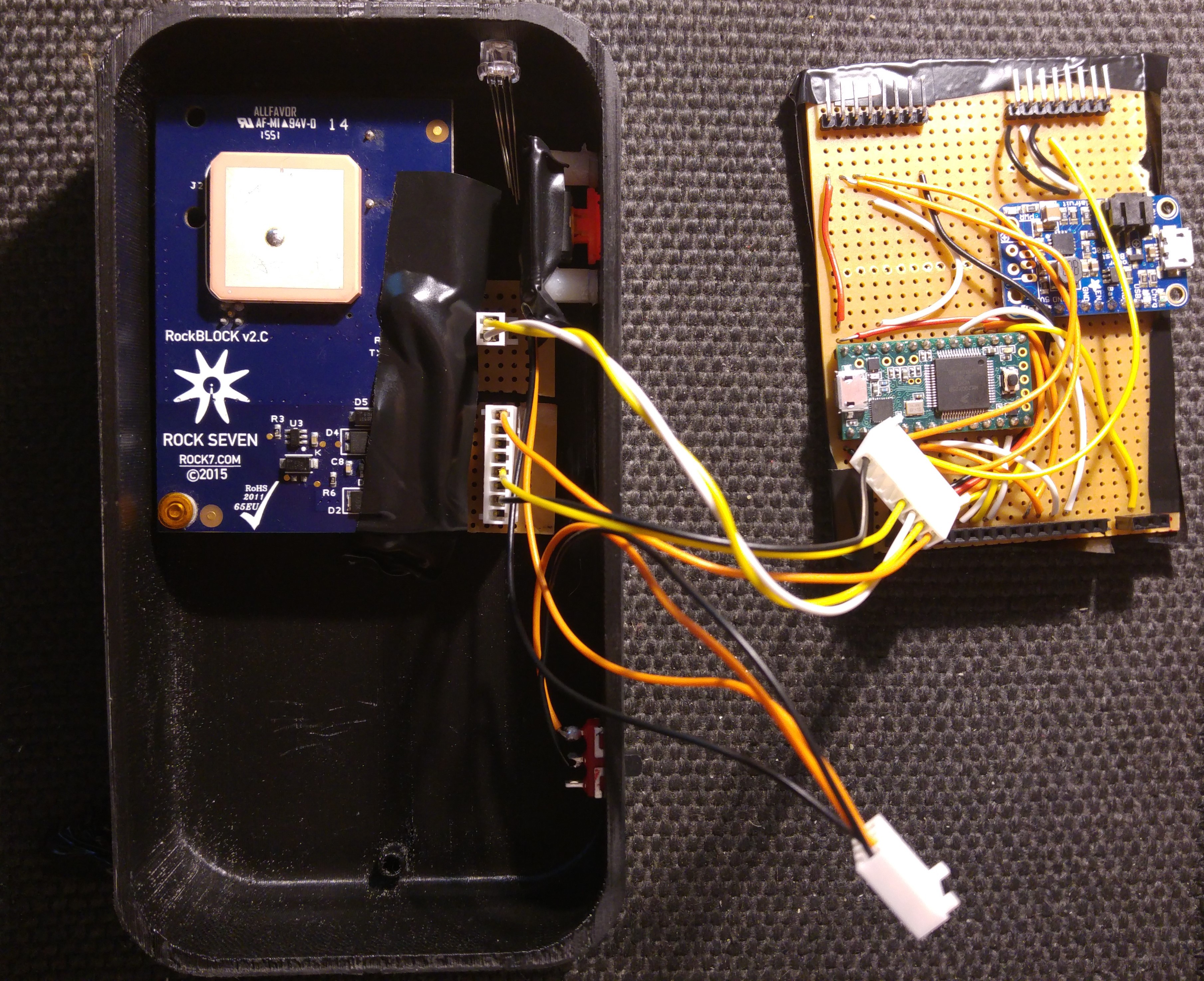
- Step 7: Setup wiring connections for the Rock7 Rockblock. I used right-angled header pins but I would have preferred to use a Molex right-angled connector to ensure the connections are solid.
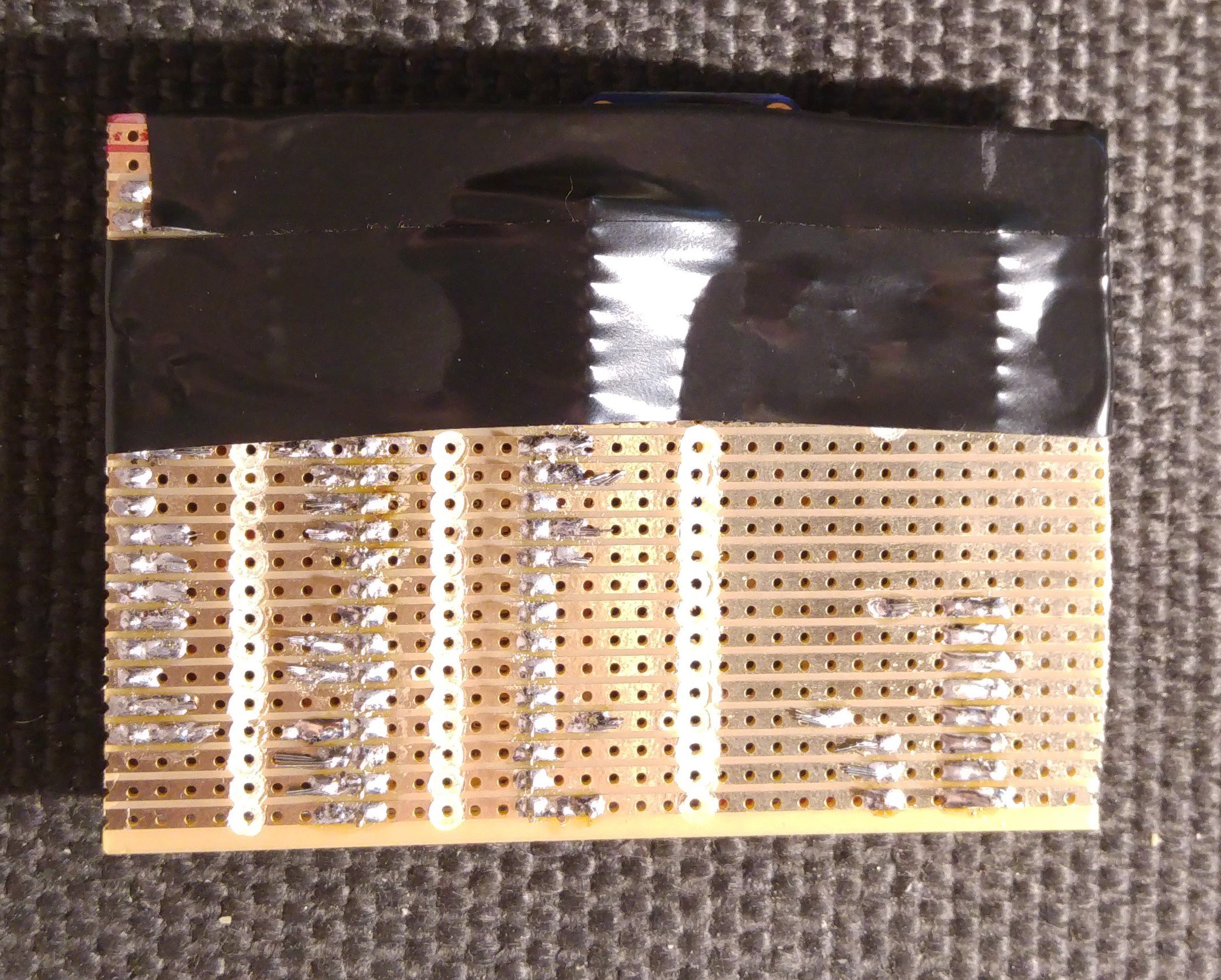
- Step 8: The Rockblock needs to have the patch antenna facing up so that when the MyComm is on the base it can still transmit. For this I used some veroboard to provide connection points for the wiring.
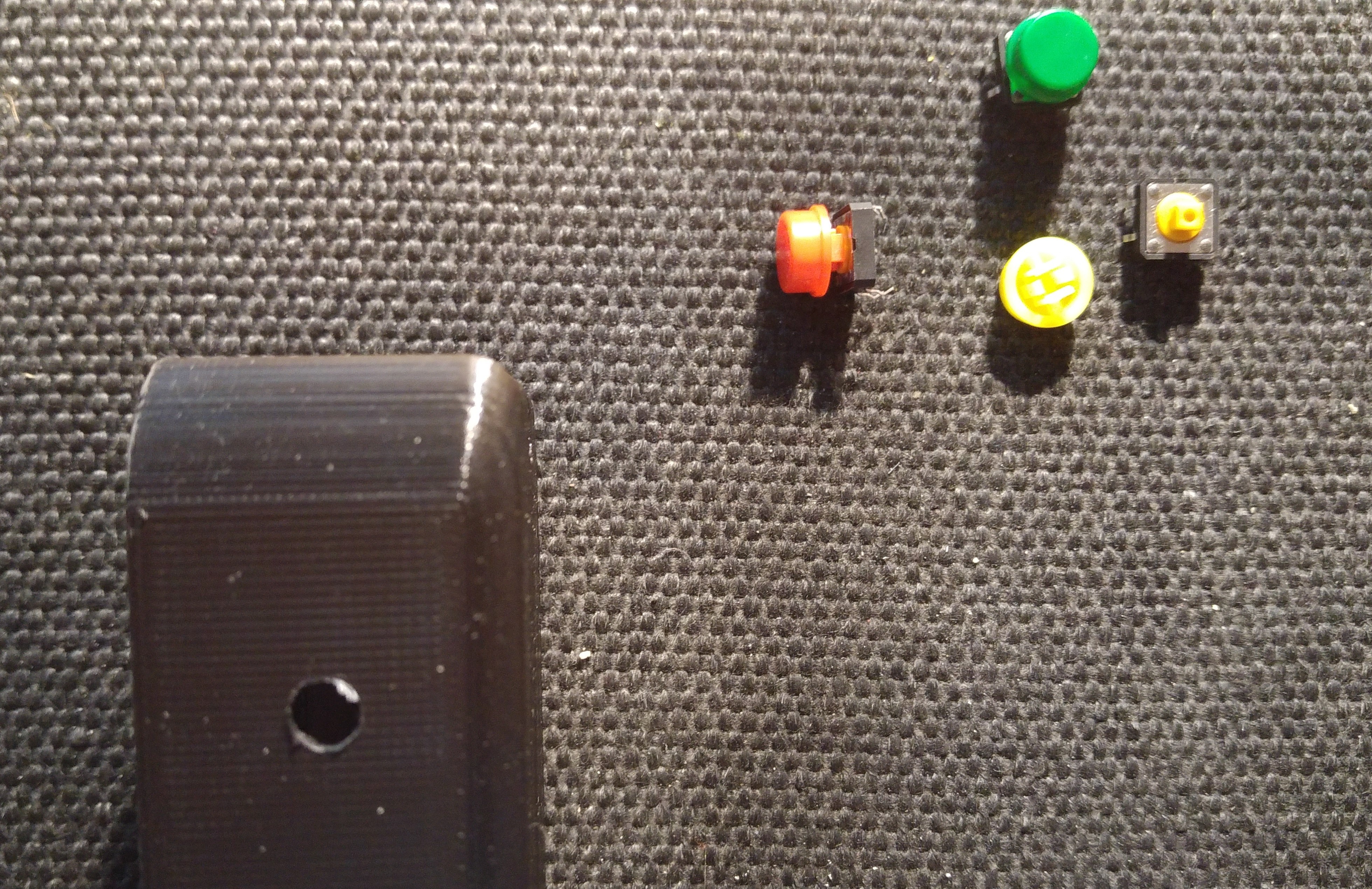
- Step 9: Setup wiring for Button and LED Connections
Assembly:
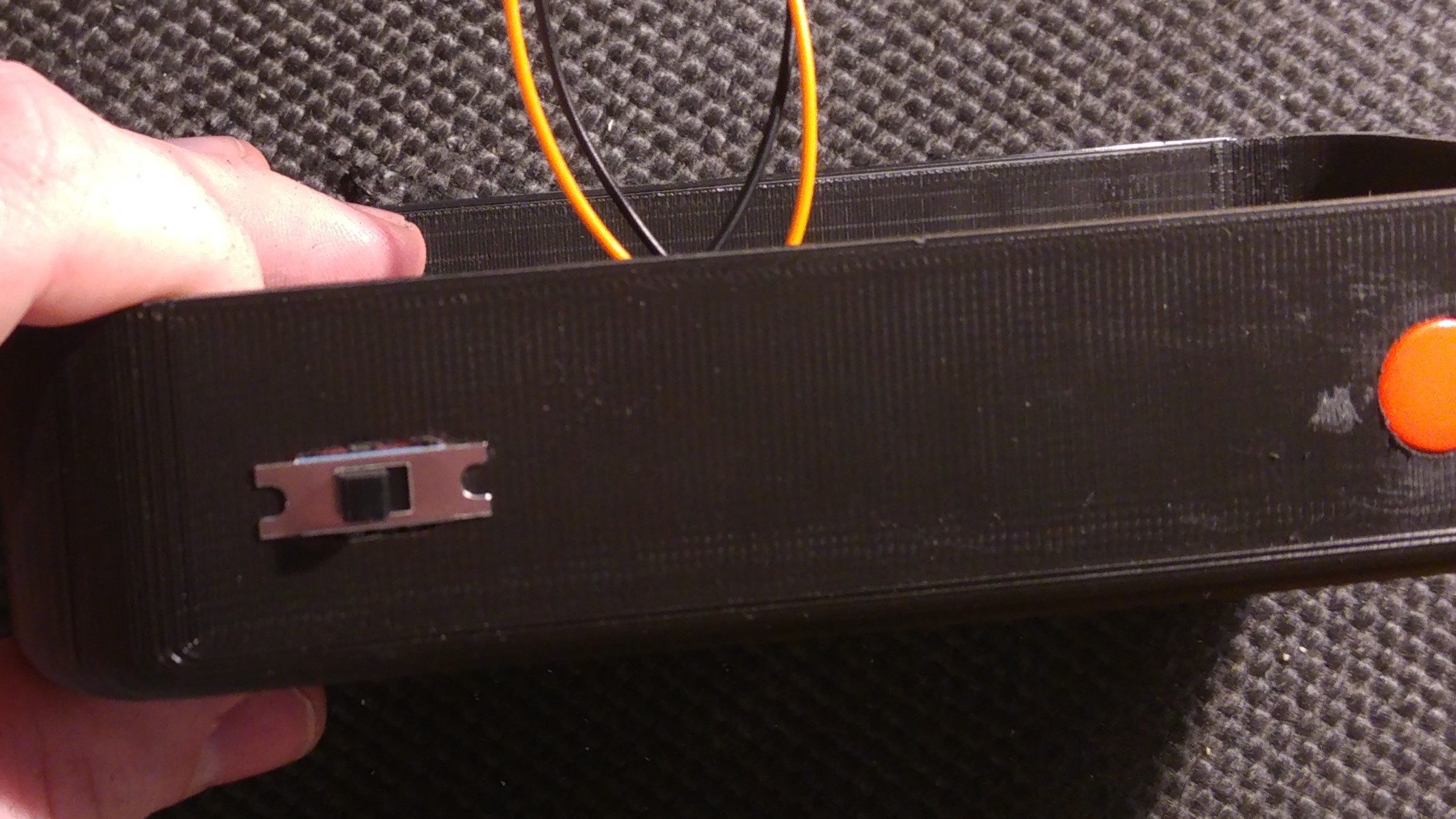
Step 10: Mount Button and LED to the Box
I used a piece of veroboard in order to mount the button to the wall of the box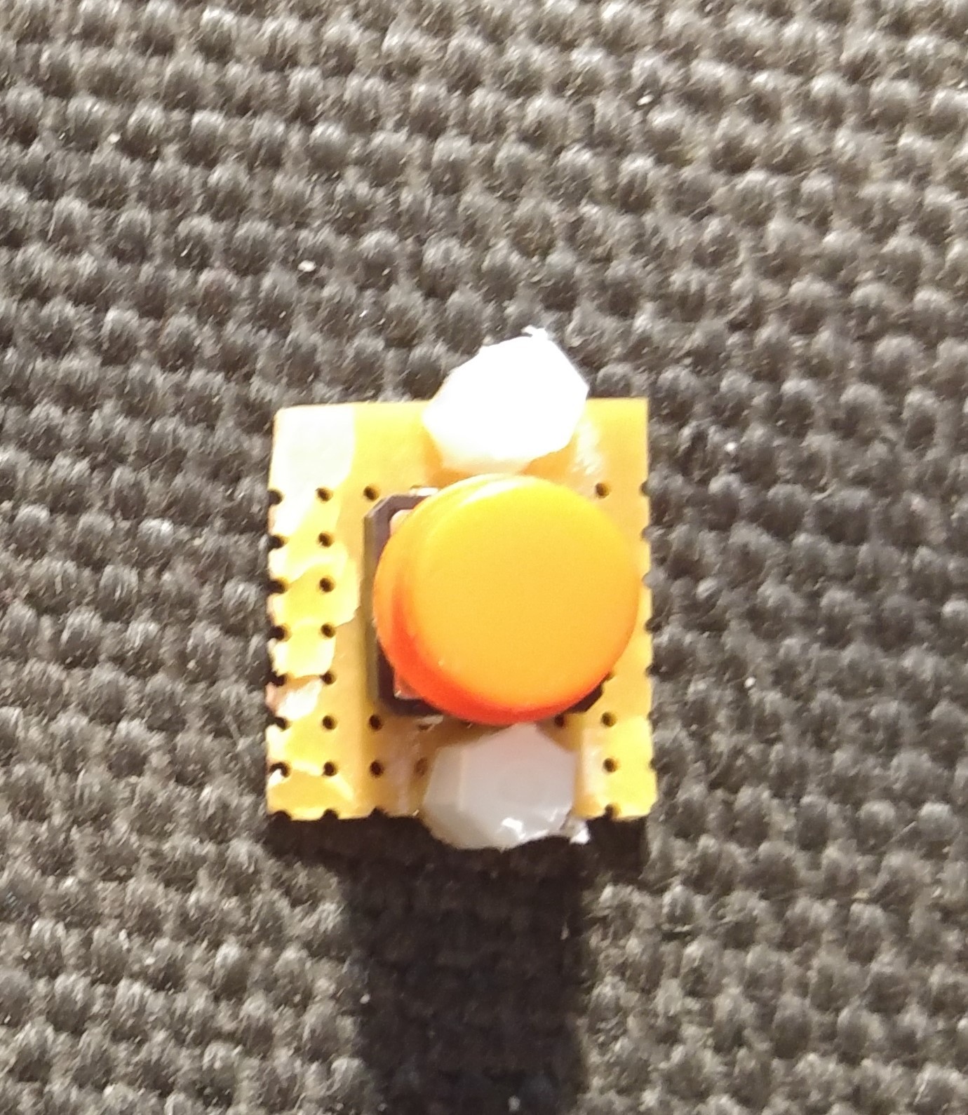

- Step 11: Secure the screen to the front Cover. (Current design needs updated to better mount the screen so I used super glue for now)
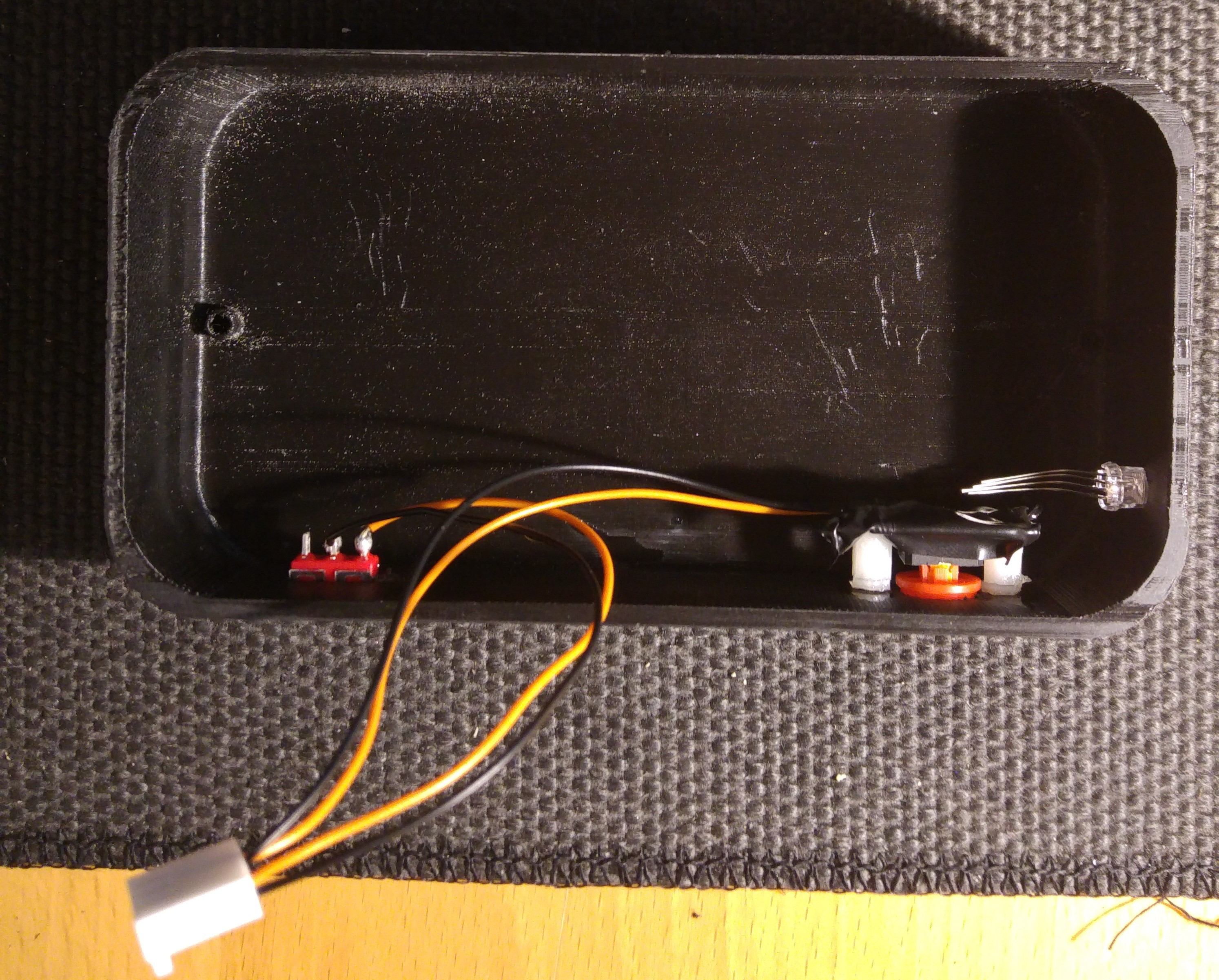
- Step 12: Mount and wire-up the buttons
- Step 13: Cover the bottom of the veroboard - I did this to provide some protection from grounding/shorting any of the elements inside the box
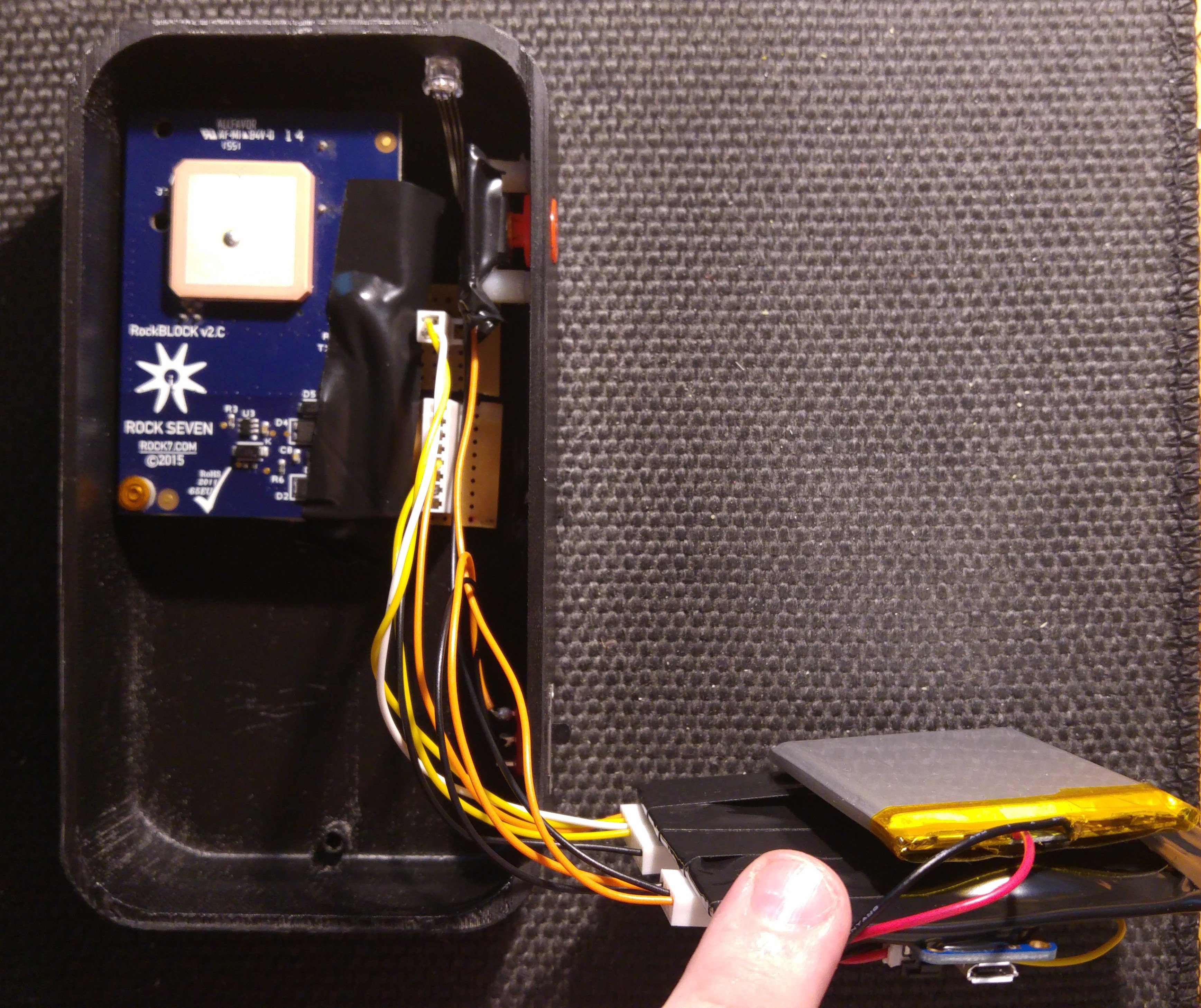
- Step 14: Assembly 1 - Place the rockblock inside the box in the top section. I used double sided tape to secure it down
- Step 15: Assembly 2 - Secure all wiring and I attached the battery with double sided tape to the main veroboard
- Step 16: Test your MyComm!
Thanks for following these instructions! Again, as you can see, this is our first attempt at assembling the first full prototype of the MyComm. There's some design changes to be made to make things easier and more practical. If you have any questions please let us know! You can see a video of the MyComm turning on for the first time below:
JW
Discussions
Become a Hackaday.io Member
Create an account to leave a comment. Already have an account? Log In.