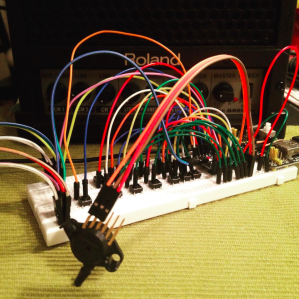
I started with very basic solutions. The only fancy component was the Freescale MPX5010GP pressure sensor. The rest was just switches and potentiometers (while waiting for the joysticks I was planning to use). From all the available pressure sensors on the market I went with the MPX5010 based on what other people had been using for the same purpose, and the GP version for the side mounted tube connection, the practical housing with screw holes and the through hole pins that could also be used with Dupont connector cables.
The Arduino Pro mini would allow me to connect enough switches and potentiometers to recreate the EWI key set and some controls for octave, pitch bend and modulation, so I could stick to my plan there. Small size, low cost.
For writing the firmware I first had a look at the page of Tom Scarff, midikits.net. I had ordered some stuff from him years ago and I remembered he had some examples on how to send MIDI with Arduino. I found he had also made wind controllers, and I had a look at his midi trombone code. It was rudimentary at best, so I just borrowed the midi routines and the comment style and figured I'd write the rest myself. I had a pretty good idea in my head how it should all come together, so I went ahead.
My main concern was how to work out the decoding of the fingering. Most people seemed to use switch case functions where all thinkable fingering combinations were listed, but knowing my EWI I thought that could not be how the decoding was made. It seemed more like there were logical conditions for each individual key. Looking around a bit for answers I found the blog of Bret Pimentel and his post on flexible EWI fingerings.
He had it all figured out. Each key changes the note value a certain number of semitones up or down, some of them with conditions. Let's list them here as variable declarations for the Arduino sketch:
// Key variables, TRUE (1) for pressed, FALSE (0) for not pressed
byte LH1;  // LH key 1 (pitch change -2)
byte LHb;  // LH bis key (pitch change -1 unless LH1 and LH2 are pressed)
byte LH2;  // LH key 2 (with LH1 pressed pitch change is -2, else -1)
byte LH3;  // LH key 3 (pitch change -2)
byte LHp1; // LH pinky key 1 (pitch change +1)
byte LHp2; // LH pinky key 2 (pitch change -1)
byte RHs;  // RH side key (pitch change -2 unless LHp1 is pressed)
byte RH1;  // RH key 1 (with LH3 pressed pitch change is -2, else -1)
byte RH2;  // RH key 2 (pitch change -1)
byte RH3;  // RH key 3 (pitch change -2)
byte RHp1; // RH pinky key 1 (pitch change +1)
byte RHp2; // RH pinky key 2 (pitch change -1)
byte RHp3; // RH pinky key 3 (pitch change -2)
byte OCTup; // Octave switch key (pitch change +12)
So all that needed to be done was to get the TRUE or FALSE values from reading the switches into those variables and make those conditions work in C code to add or subtract from the MIDI note number stated as startNote. In this case it is C#-3 with note number 61, the note playing if no keys are pressed on the controller.fingeredNote=startNote-2*LH1-(LHb && !(LH1 && LH2))-LH2-(LH2 && LH1)-2*LH3+LHp1-LHp2+(RHs && !LHp1)-RH1-(RH1 && LH3)-RH2-2*RH3+RHp1-RHp2-2*RHp3+12*OCTup;Now, that was it! I had confidence in this now and went ahead full steam :)After wiring everything up on a breadboard and trying the controller out I realized most stuff was working just as I wanted it to, but there were serious issues with my main loop making notes stick and whatnot.
Trying to make the flow work, I did some additional internet searches on the matter and then I found the Gordophone blog by Gordon Good.
His step by step instructions on how to make Teensy/Arduino wind controllers included a very easy to follow state machine flow for the main loop. It seemed perfect, so I just inserted my code in his state machine and it all worked! I was thrilled, and immediately contacted him to say thanks and to let him know. I also wanted to share my thoughts on fingering to note calculation with him. He was very glad to hear from me, and he asked me If I would like to write a guest post about it on his blog. That sounded like fun, so I did.
So... finally I had a working breadboard prototype, and it looked like this:

https://www.instagram.com/p/BEN1oIuoVba/?taken-by=trasselfrisyr
and..
https://www.instagram.com/p/BES5hIPIVdv/?taken-by=trasselfrisyr
...and yeh, Instagram is where I've kept people updated on my progress along the way. You should really check it out :)
https://www.instagram.com/trasselfrisyr/
The firmware for this state of the project is still available for reference.
 Johan Berglund
Discussions
Become a Hackaday.io Member
Create an account to leave a comment. Already have an account? Log In.