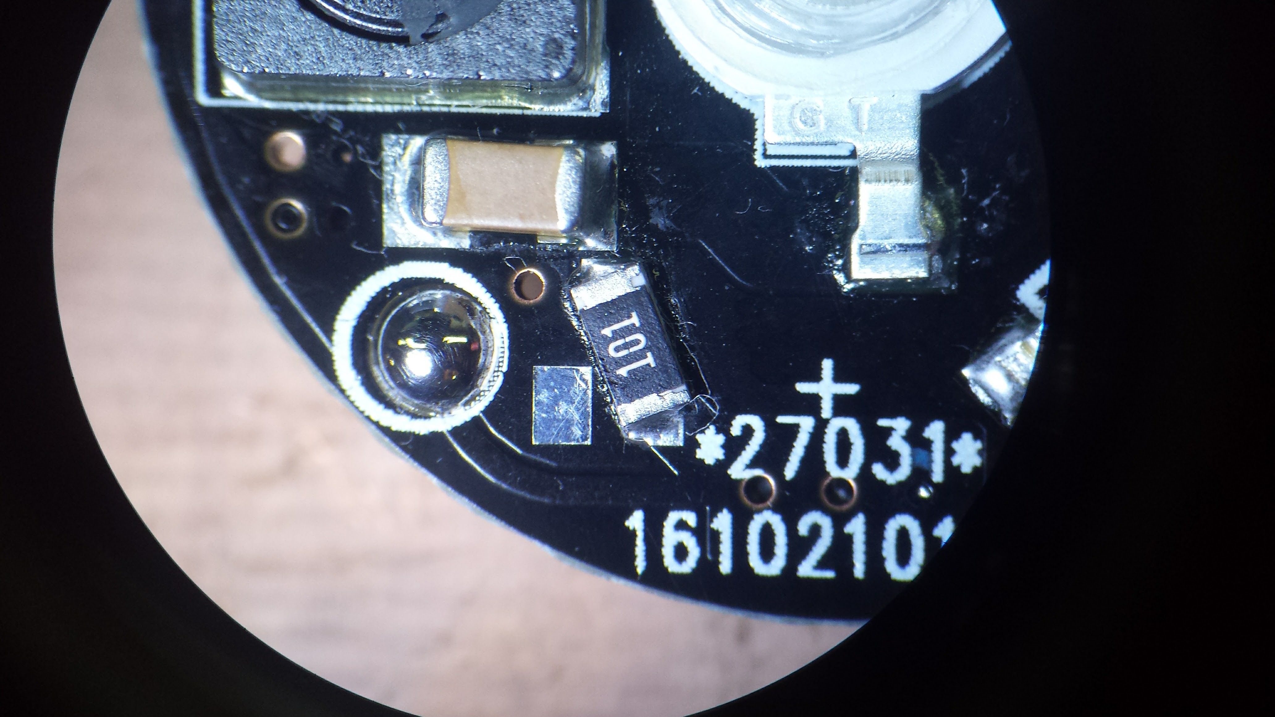
I received a batch of V2.1 PCBs this week - this was the board where the reverse-battery-protection MOSFET was backwards. Rather than leave it out, I decided to use a 100-ohm 1206 resistor instead. This limits the current in case of reverse insertion, and protects against rogue PIC code holding the pulse MOSFET on. The resistor is actually a decent fit on two pads of the incorrect SOT-23 MOSFET footprint:

This resistor is designed in as part of the V2.2 board, in addition to a properly-connected P-channel MOSFET to handle reversed batteries. I usually give boards a quick look under the microscope after reflowing them on the skillet, if only to remove the occasional solder blob, and everything on this one looked fine.
When I went to program this board, though, I kept getting errors - the device ID was always read as 0,and if I persisted, programming failed. At first I thought that there was flux on the programming pads so the pogo pins weren't making good contact. I cleaned the pads with alcohol, then shined them with a pencil eraser, but no luck. I finally soldered wires to the pads to connect directly to a programming header - same problem.
Then I started to wonder about that resistor. Here's how it looks in the circuit:

The ICSP connections are shown as bubbles. For programming the TritiLEDs, I power the PICs from the programmer - they only consume microamps when they're running, so there's no problem. I think what's happening is that the Vdd to the chip takes a little while to come up, having to charge the 10uF cap through the 100 ohm resistor. This prevents the PIC from going into programming mode when the Vpp line is raised.
After some searching, I found the MPLAB IDE setting for "Apply Vdd before Vpp" with the PICkit3. With that set, the board programs just fine. Elapsed time to debug problem: 3.5 hours. This included some very close observation of this new batch of boards - discussed below. The Vdd programming pad is on the other side of the resistor on the V2.2 board, which is why I didn't see the same problem there.
There's another problem with these boards besides the reversed MOSFETs. The boards have a HASL finish - this can be a problem for battery contacts - with the CR2032 holders I'm using, one of the contacts is a pad on the PCB. Memory Protection Devices, which manufactures many coin cell holders, recommends nickel or gold finish for these contacts in their application note. I think I'll have to pay for ENIG going forward. It's not as good as "hard gold," the thicker coating usually used for edge connectors, but it's probably much better than HASL. Even if the thin ENIG gold were to wear off, there's nickel underneath (some thickness, anyway). Another reason to use OSH Park.
I actually got two batches of boards in the mail this week - one was the V2.2's from OSH Park, which looks like it may be the final PCB design for version 2 - I'd like to assemble a few more of them and run some more tests before I declare victory. The other was the V2.1's from dirtypcbs.com. This was my first experience with this service, and they seem OK - quality maybe a little worse than iTead (not even in the same league as OSH Park), but they're cheap and they warn you over and over that their boards are dirty. You can see the mis-alignment of the soldermask and silkscreen in the image above - look at the programming pad (now blobbed with solder). They do offer your choice of soldermask color for no extra charge. Even though the electrons don't care sometimes you do.
 Ted Yapo
Discussions
Become a Hackaday.io Member
Create an account to leave a comment. Already have an account? Log In.