After some discussion with the application engineer at DigiKey and a bit of hacking, I think I understand how temperature compensation on the MLX90393 works well enough to incorporate it into the driver. It will take some time to re-write the code incorporating what I've learned, but I wanted to get this documented while it's still fresh. I might be wrong about any or all of this; if you notice an error, or have different information about this part, please let me know. Part of the problem is that the factory-supplied parameters just seem to give lousy results, so for a long time I figured I was using the part incorrectly. I don't think so anymore.
Temperature Sweeps on the Cheap
To test temperature compensation, you need to have a way to sweep temperature. I actually have a cobbled-together environmental chamber consisting of a thermoelectric heater/cooler controlled with a decent thermostat. However, using it for these experiments was inconvenient, so I used a simpler technique. Since the MLX90393 has an on-die temperature sensor, you can generate temperature sweeps by heating (or cooling) the part and collecting data while it drifts back to ambient. This technique has a few potential problems, including the accuracy of the on-die temperature sensor and the exponential temperature curve. The later causes the temperature to move too quickly at the beginning (hot or cold) of a sweep, and too slowly as the part equilibrates to ambient. You might improve the technique with an insulating blanket (say of Styrofoam) slipped over the part after the initial heating/cooling, then removed once the sweep rate drops. I didn't bother.
Here are the tools of the trade:
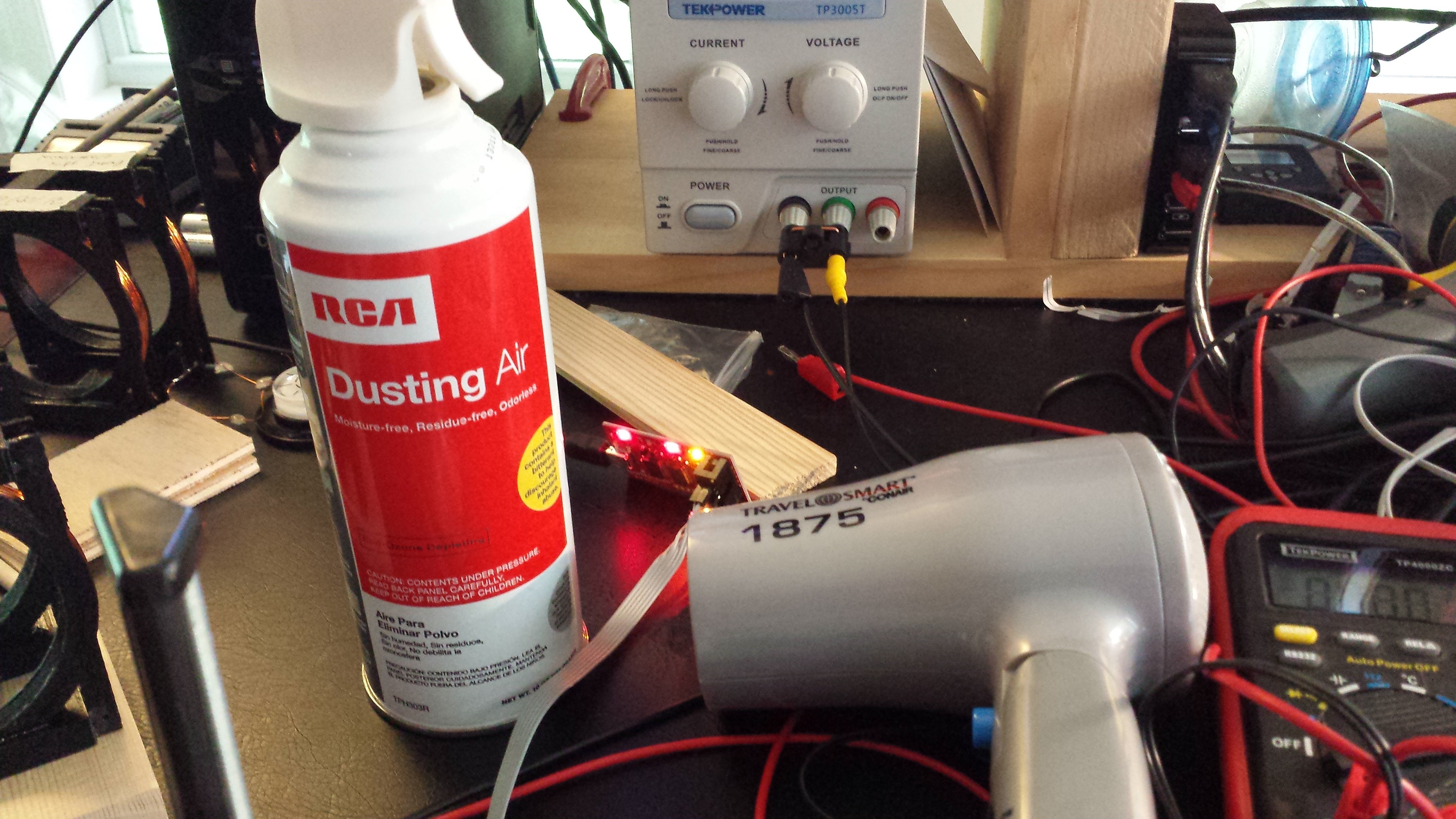
The "canned air" is actually 1.1-Difluoroethane, a refrigerant with a boiling point of -25C. The label explicitly tells you NOT to spray with the can upside down, so don't do it! But when you do, you get a stream of liquid coolant instead of the gas. A brief shot of liquid on the device-under-test brings it below 0C to start the cold sweep. This is much cheaper (and more widely available) than official "cooling spray." The hair dryer (which I could use in my youth, but is unnecessary now) is self-explanatory. I didn't use a heat gun since it would be too easy to harm the PLA printed components, epoxy, or even solder joints. Here's a plot of a typical temperature profile for the part mounted in my epoxy potting:

The datasheet lists -20 to 85C as the operating temperature range, but I'm going to assume people can make do with a more narrow range in the magnetic field scanner.
Configuring Temperature Compensation
As far as I can glean from the available documentation, the on-chip temperature compensation algorithm is controlled by 7 parameters:
- TCMP_EN : boolean which enables temperature compensation
- TREF : breakpoint for piecewise-linear compensation algorithm. Factory trimmed
- Sens_TC_HT : high-temperature compensation coefficient. Factory trimmed
- Sens_TC_LT : low-temperature compensation coefficient. Factory trimmed
- Offsets (x, y, z) : "offsets" for x, y, and z
TCMP_EN is self-explanatory, and TREF and the two coefficients are programmed into nvram at the factory (more about this later...), leaving just the offsets to figure out. The datasheet is not exactly lucid about the offset parameters:
OFFSET_i[15:0] : Constant offset correction, independent for i = X, Y, Z
Probably realizing this, Melexis was kind enough to write a simplified "getting started" document explaining how to use this part. Here's the section concerning the offset parameters:
OFFSET_X, OFFSET_Y & OFFSET_Z
These parameters are used to compensate the offset in case the temperature compensation is enabled. They are not used with TCMP disabled. Please refer to the application note on the temperature compensation for more info. These values can be blindly programmed to the values given in this document (if not already programmed).
The values come programmed to zero in the nvram, and no values are actually given in the document. Blindly, indeed! The application note mentioned has a single line describing the offsets:
For example if the offset measured without the temperature compensation enabled equals 200LSB, the
offset programmed will become 32768+200=32968=0x80C8.
Ahh, now it makes sense. You measure them. Whatever that means.
The application note does give the formula for the compensation algorithm, and it's just a two-section piecewise linear function. They even provide the gain parameters, so we just need to measure offsets. As far as I am able to determine, these should be initialized with the values the part generates in no magnetic field. Unfortunately, we're constantly immersed in the geomagnetic field, so setting these registers isn't as simple as it should be. My current theory is that for the intended application of this part (position sensing with strong permanent magnets), the geomagnetic field can be treated as zero when setting these registers. In the scanner application, however, I'd like to measure fields of this strength with reasonable accuracy, so I need a way to initialize the offsets for a true zero field.
Creating a Field-Free Volume
The Helmholtz coil article on Wikipedia notes that the coil can be used to cancel the Earth's field, although the supplied reference and link didn't seem to explain how. I thought about it a bit, and the procedure is similar to what I had done before to verify the coil, except I changed things around so that you don't need to rely on a model to predict the geomagnetic field at your location. The idea is to use a tangent magnetometer to set the coil field to exactly the local geomagnetic field, then orient it in the opposite direction so the fields cancel. Here's the step-by-step procedure:
- Level the coil, place a small compass inside, and turn off the coil current
- Using the compass, orient the coil east-west
- Adjust the current until the compass deflects 45°. The coil field is now equal to the local geomagnetic field.
- Turn off the current, and use the compass to align the coil north-south
- Turn the current back on; the center of the coil is now field-free in the x-y plane (or you got it wrong and you have a 2x field, which is easy to detect)
The compass needle swings freely in the absence of a field - you can move it around with the tip of a screwdriver (magnetized or just steel), and it will stay where you put it. Pretty neat.
Here's an image of the small compass I found on Amazon. It fits entirely inside the 25mm 1% field-error sphere in my coil. The compass card it came with was impossible to read, so I printed a new one with only eight points. I also painted a fine black line on the needle with a sharpie pen to aid alignment. Mechanically, it's still cheap crap, and suffers from a bad case of stiction, often requiring a gentle tap to align itself in the field. Good enough, though.

Compensation Results
At ambient temperature (c. 22C), I measured the z-axis offset in the zero-field to be 150 counts (it actually varies from 146 to 153 with noise, but 150 is a strong mode of the distribution). Using this as the z-offset, and the factory-programmed parameters for the other values, I measured the following sweep for the zero-field setup (which used a coil current of 7.85mA in this location):
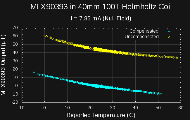
Not too great. The offset has brought the field measurement (at ambient temp.) from mid-40s to near zero, where it should be, but the temperature dependence doesn't seem very much improved. Undaunted, I moved on to measure the results with the coil current removed - this is just the geomagnetic field:
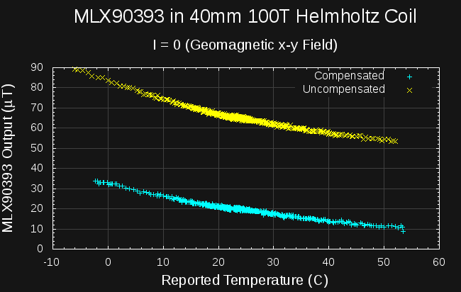
Again, I don't see much improvement in the temperature dependence, although the value around ambient temperature is approximately correct - the World Magnetic Model predicts a field of 19.585 μT here. Next, I added 1A to the zero-field value to produce a predicted field of 2214 μT:
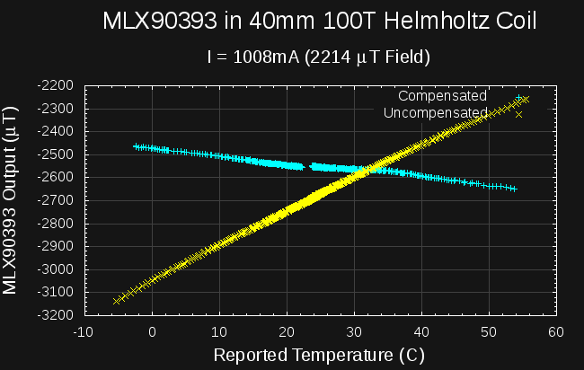
Now we see some temperature compensation. The scaling is still off by maybe 15%, but the temperature compensation is definitely flatter. Not flat enough, though - there's still some linear dependence left in there. There's a section in the app. note that says the coefficients should be adjusted by fixed values after programming at the factory. I applied the values they suggest, and there's some improvement, but the resulting line isn't particularly flat. Instead, I tried all the values in a range around the factory-supplied coefficients, testing each one for flatness of the result (as measured by linear regression on the resulting data points). The next image shows what the offsets (SENS_TC_HT - 17, SENS_TC_LT - 14) = (69, 54) yield. (I'll note that the values suggested in the app note are 0x67 and 0x55 - could they have mistakenly written decimal values as hex??)
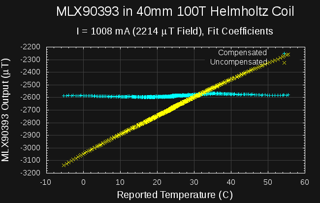
Much better! Unfortunately, these same values may not work for every MLX90393, and running through this whole temperature sweep process to calibrate the sensor simply isn't going to be possible on the scanner (I think). I will have to look at a few parts to get an idea for the variation. Melexis thinks there's enough part-to-part variation to program the coefficients from measurements at the wafer level, so I'd be very surprised if my hand-tuned values work universally. Obtaining good accuracy on the scanner will require some more thought. Then there's this - even with these new coefficients, the low-field compensation is still lousy:
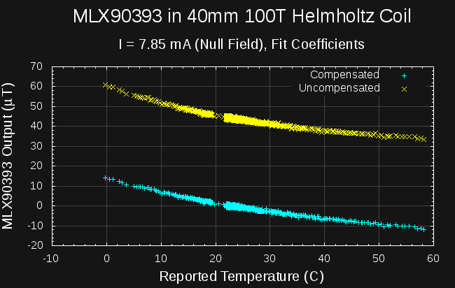
Now, I'm wondering if the fixed-point arithmetic used on the part for this compensation only works properly for large values. I'll have to try doing in floating-point (external to the part) and compare the results.
Next Up
I keep telling myself I'm going to scan some fields. Maybe I should do so.
 Ted Yapo
Discussions
Become a Hackaday.io Member
Create an account to leave a comment. Already have an account? Log In.
Do you schematics of your Helmholtz Coil design by any chance ?
Are you sure? yes | no