 SHAOS
SHAOSI decided that interface between ZIF-socket and host machine will be implemented with help of this antique ISA backplane manufactured in 1984 (I bought it for about $20 last month):
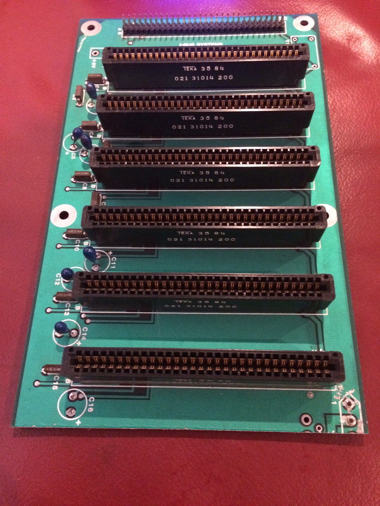
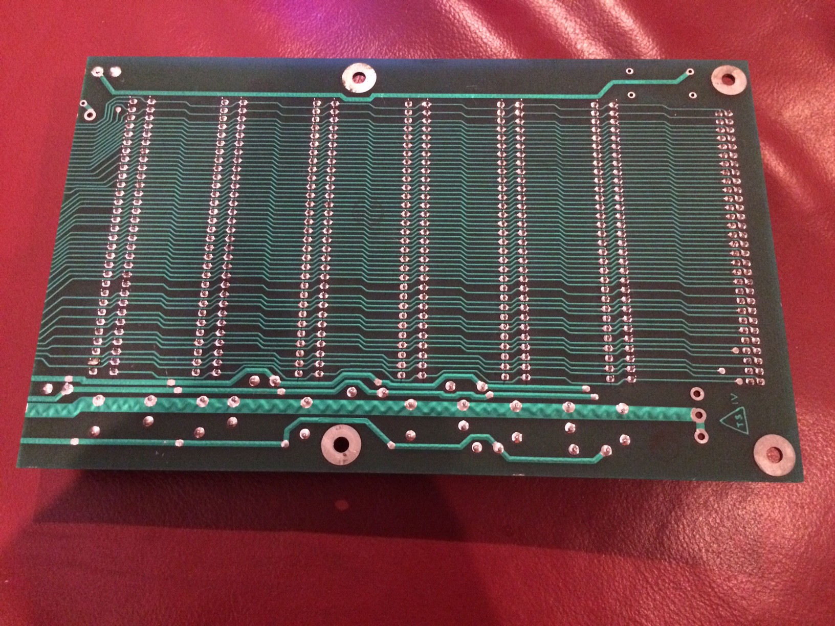
I cut out it a little to remove part with pull-up resistors, because it shortened power to the ground somewhere. On the back we can see all signals go through so technically this board could be easily used to implement any custom backplane solution:
For my task I will use part of upside-down ISA-socket where quasi-disks and peripherals (including tester/programmer) will be inserted:
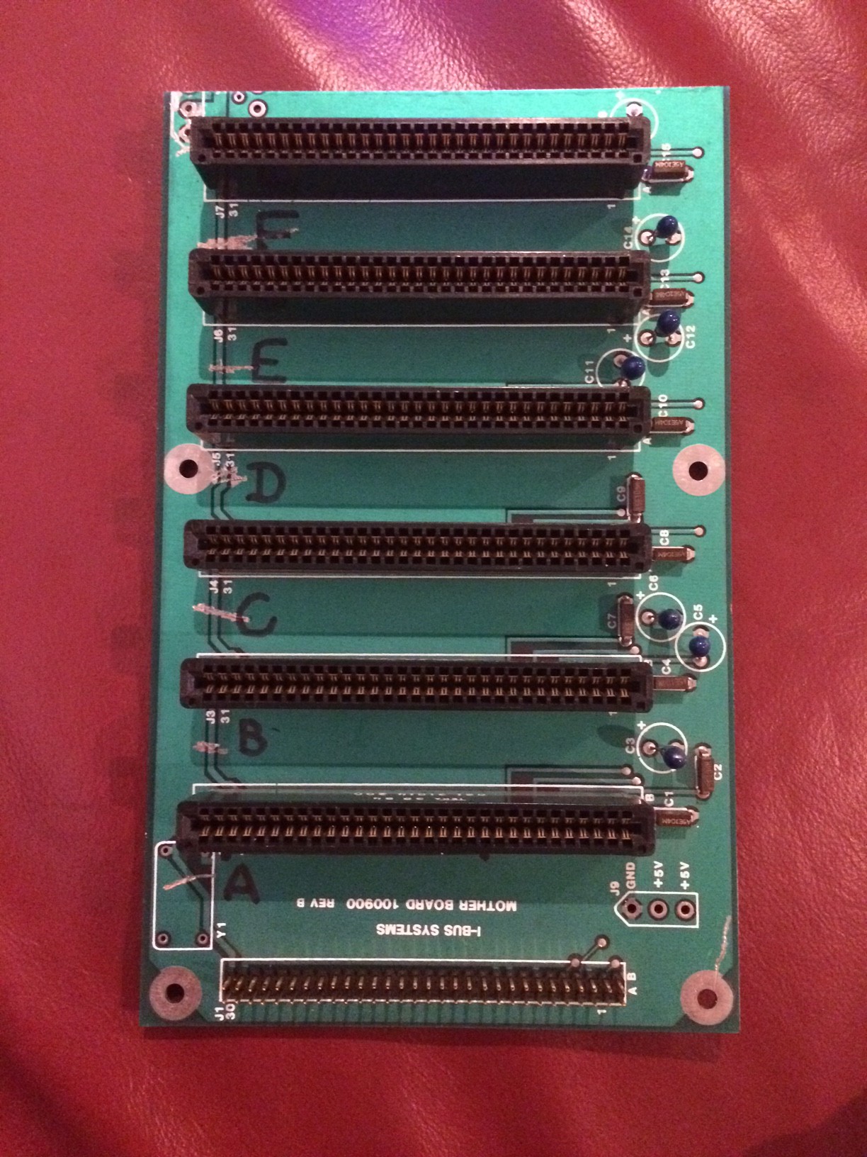
I marked places A,B,C,D,E and F. Also I cut wire that was used as CLK in ISA - now it will be repurposed as individual /CS for every board. Pinout of the socket in this case uses only 42 contacts from socket and most of them repurposed, so it is NOT an ISA bus anymore (I only kept +5V, ground and partially address on their usual locations):
| 1 | A0 | GND | 42 |
| 2 | A1 | /CS | 41 |
| 3 | A2 | VCC | 40 |
| 4 | A3 | X7 | 39 |
| 5 | A4 | X6 | 38 |
| 6 | A5 | X5 | 37 |
| 7 | A6 | X4 | 36 |
| 8 | A7 | X3 | 35 |
| 9 | A8 | A23 | 34 |
| 10 | A9 | A22 | 33 |
| 11 | A10 | A21 | 32 |
| 12 | A11 | D7 | 31 |
| 13 | A12 | D6 | 30 |
| 14 | A13 | D5 | 29 |
| 15 | A14 | D4 | 28 |
| 16 | A15 | D3 | 27 |
| 17 | A16 | D2 | 26 |
| 18 | A17 | D1 | 25 |
| 19 | A18 | D0 | 24 |
| 20 | A19 | /RD | 23 |
| 21 | A20 | /WR | 22 |
All signals are shared across all sockets except for /CS that individually wired to every slot (8 CS generated by X0,X1,X2 and that's why those 3 bits are not routed into the socket).
You can ask why tester needs quasi disk interface? I think it's cool when device may provide software to control itself right away - so ROM disk C may have a program with component library to run (I can do this program capable to work on many 8080 compatible machine, not only Soviet clones of ZX-Spectrum) and RAM disk A may be used to store test results...
Discussions
Become a Hackaday.io Member
Create an account to leave a comment. Already have an account? Log In.