This is just a quick explanation of the basic LED power control system I use in my RTI controller. You might find it useful in understanding how things work, and I hope it's not too technical; but you don't have to understand this to build the system.
I first started working on this project early in 2013. I knew the control system would be driven by an Arduino, since the control requirements were pretty basic - turn lights on and off, fire a camera shutter in sync with the lights. But while an Arduino Mega has enough pins to control an adequate number of LEDs to do RTI (around 50+), wiring those pins individually to LEDs would be a nightmare. And in any case the Arduino wasn't going to be adequate as a power source to light up the LEDs - the maximum current any Arduino pin can safely supply is 40 mA, with 20 mA the recommended maximum for continuous output. That means about 100 mW of power at best, which would have limited me to small domes and long camera exposure times. What's more, for good control of LED light intensity, critical for good RTI results, you need to control LED current accurately.
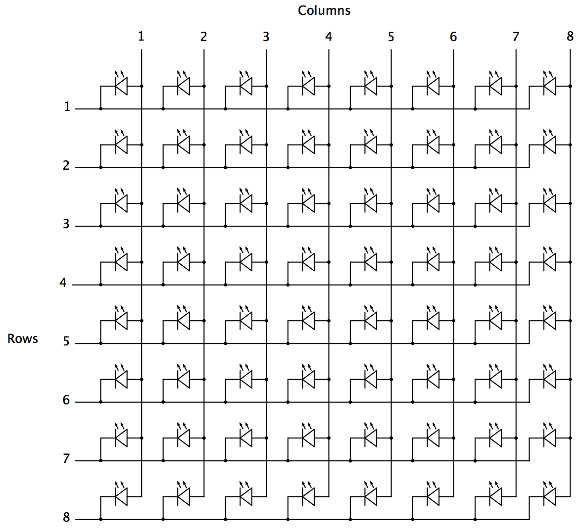
The solution to the first problem is to wire up the LED lights in matrix format:
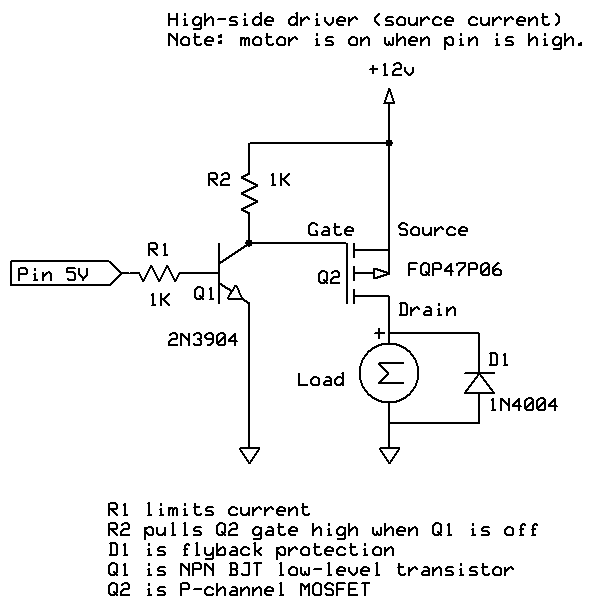
The second problem, high and accurate LED currents, requires circuitry on both the high and low sides of the LED. Here's the solution I came up with:
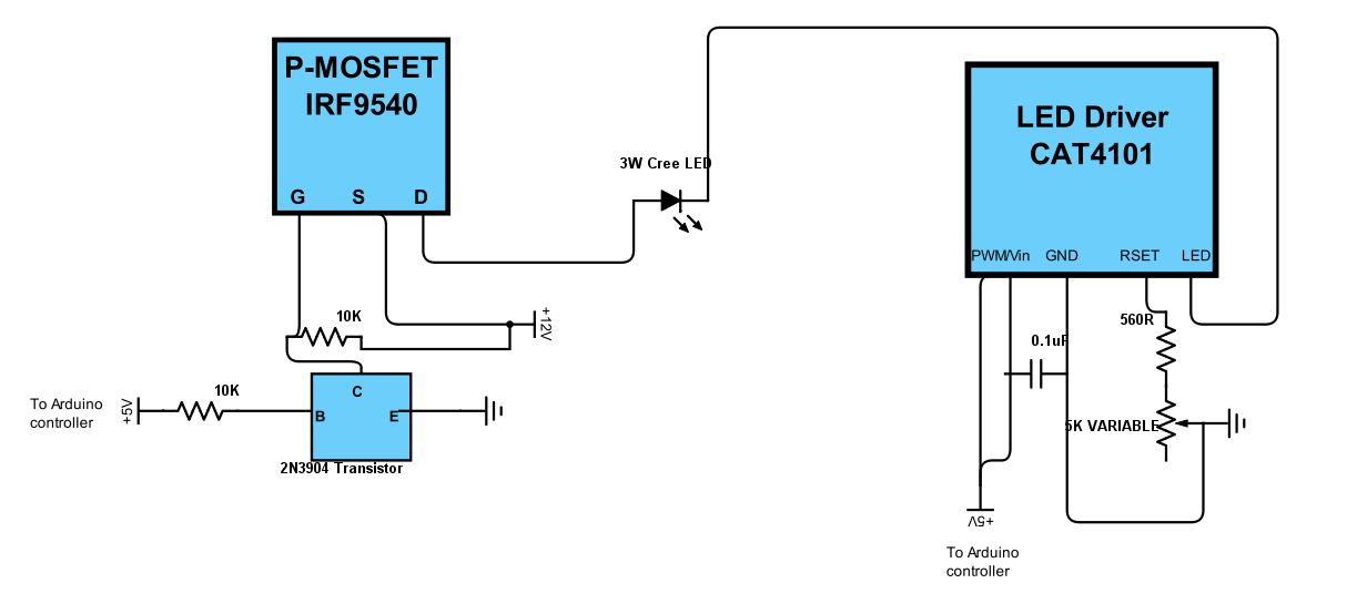
On the right-side of my schematic is the low-side driver/control, a CAT4101 LED driver that not only switches on and off the low (ground) side, but allows you to set a desired current between 150 mA and 1 A. This is a 5-pin chip. The first pin, EN/PWM, switches on the LED and can control intensity through Pulse Width Modulation; the 2nd pin, Vin, supplies +5V of power to the chip. I have these two pins bridged in my control system, so that the same Arduino controller pin both switches the chip on and supplies power. I did this because leaving all of the CAT4101 chips powered on continuously led to some weird issues with multiple LEDs turning on even when only one should have. The GND pin goes to ground. RSET connects to resistors that set the output current, with 560R giving you about 1 A, the maximum. The 5K variable resistor lets you fine-tune the current to allow for variations between different chips, and also allows you to set currents lower than the max 1A. This is useful for extending the life of the LEDs by keeping them from overheating, and also in certain use cases. For example, I sometimes use USB microscopes for micro-RTI, and full LED intensity is usually too bright for those; if I turn the current down to 150 mA, then there's no problem with sensor saturation. Finally, the LED pin connects to the ground side of the LED.
The schematic shows one high-side and one low-side driver, connected to one LED. But in the control system, there are eight high-side drivers, each connected to a column in the LED matrix, and 8 low-side drivers/constant current controls, each connected to a row in the matrix. Each driver is connect to an Arduino controller output pin that can turn it on and off as needed in software. This setup can drive a Cree 3W LED to its full power limit, at a current of 1 A.
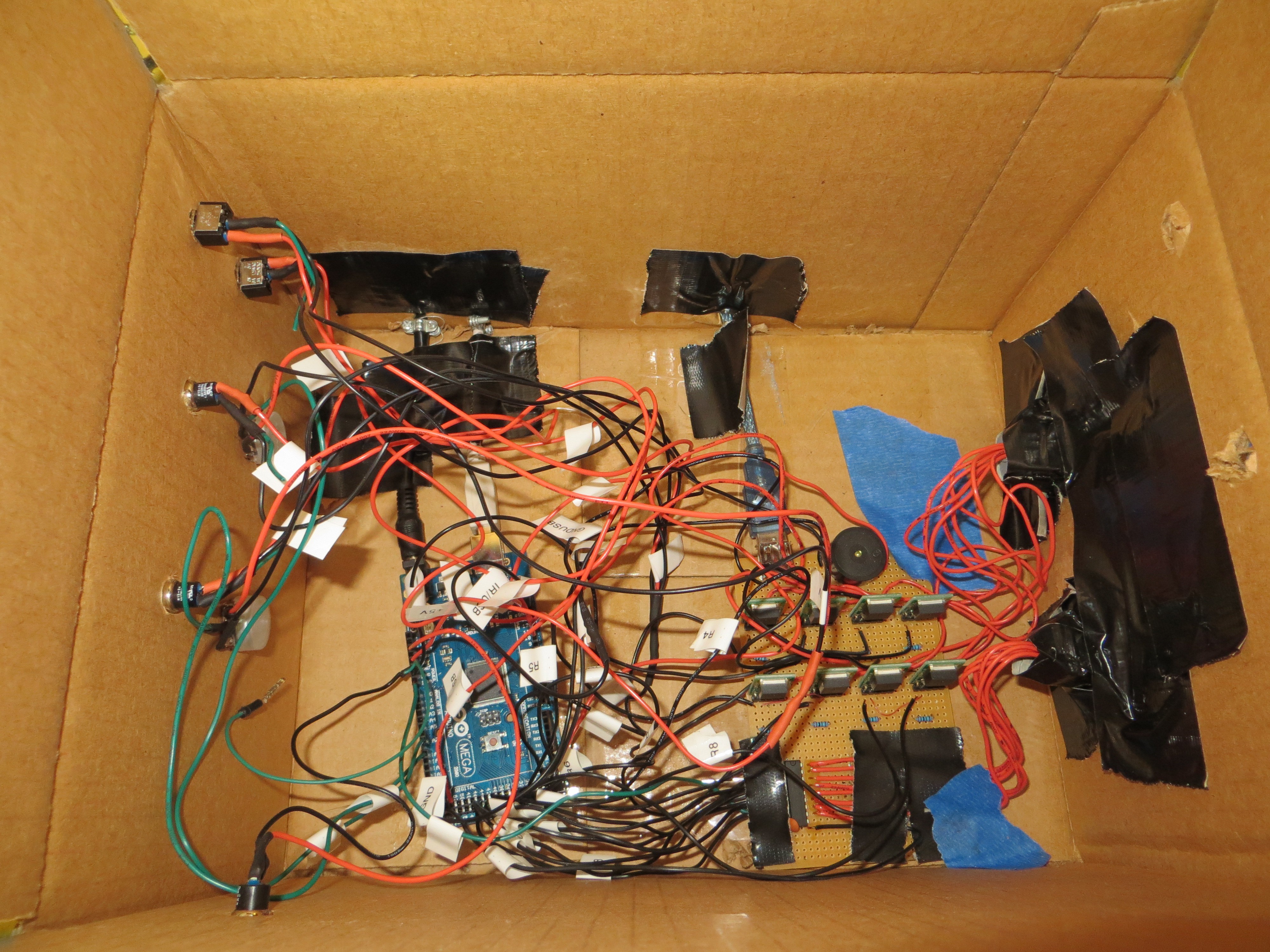
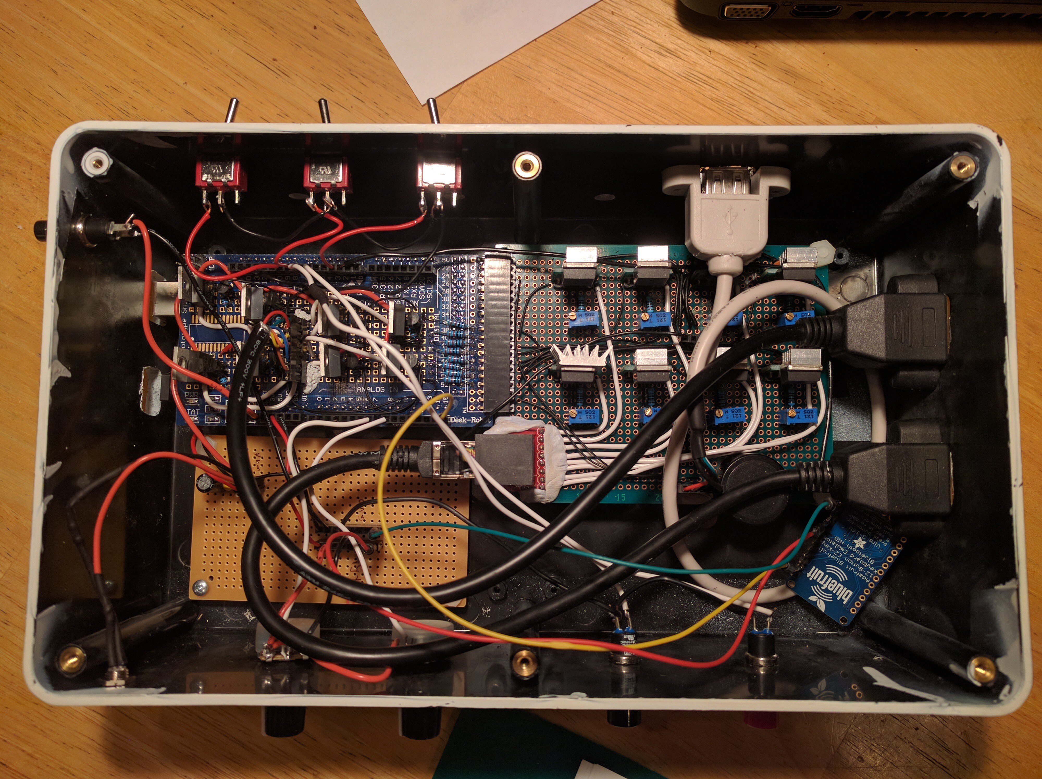
Just for laughs, here's the inside of my original controller box from 2013, using a Darlington array :
Discussions
Become a Hackaday.io Member
Create an account to leave a comment. Already have an account? Log In.