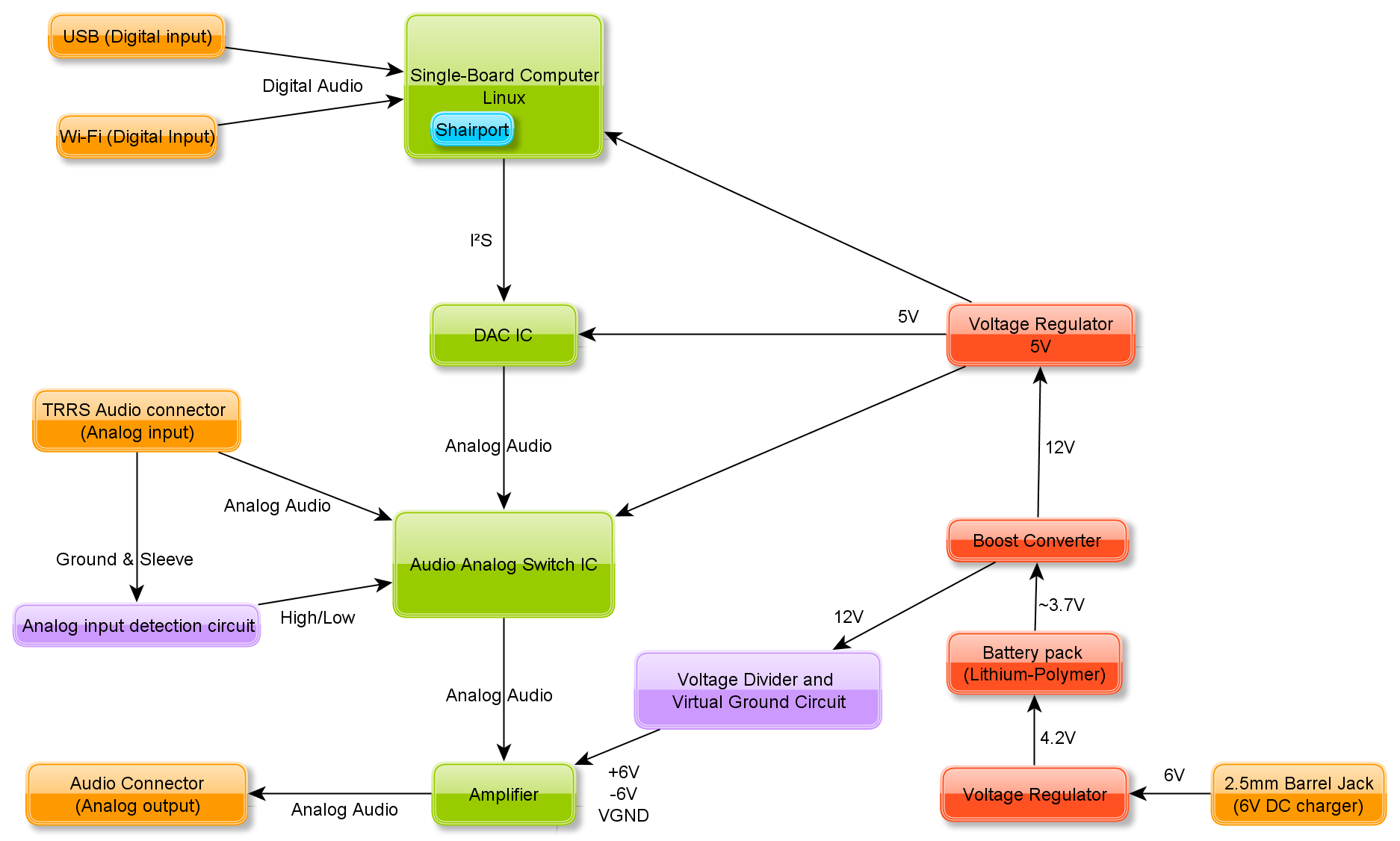
I made this diagram to help plan out the design and visualize the components required.

In order to get the Single-Board Computer to connect to the audio source, I am planning on using Shairport. The Shairport package allows audio to be played through Wi-Fi using AirPlay sources and iOS devices.
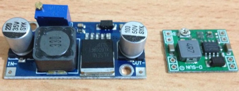
Since I want this system to be light and portable, I'll use lithium-polymer batteries in parallel. They can be made very thin and light and I already have a few small ones lying around. These types of batteries can be dangerous if not properly maintained though. Initially, I was planning on using several in series to get a high enough voltage for an amplifier circuit, but the issues with balancing their charges meant an overly complicated circuit. Instead, I'm going to use a reasonably cheap adjustable boost converter board to step-up the voltage (blue board in image below). The board I'm using has a switching frequency around 400 kHz which is way higher than human hearing, so noise shouldn't be a problem.

For simplicity, I'll charge the lithium-polymer batteries using a constant voltage of 4.2V. This can be obtained from an old 6V DC wall wart and an adjustable switching voltage regulator (green board in image above). Another regulator can be used to get the 5V required for the ICs.
In order to get the most out of the device, I want to add the option of running analog audio through the amplifier bypassing the SBC and DAC. This means that the amplifier can still be used with a source that has a headphone jack. Instead of a switch, I wan to use a 4-pole audio jack (TRRS) to determine if an analog cable has been attached or not and switch the signals accordingly.

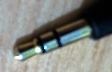
This is the jack from the pair of headphones. The tip provides the left signal, the ring in the middle provides the right signal and the sleeve is the common (ground). A TRRS jack has an additional ring, which is generally used for a microphone. However this can also be used to detect if a plug is inserted, as it will connect the second ring to the common. This will change the resistance significantly, which can be used to provide switching logic to an IC.
Discussions
Become a Hackaday.io Member
Create an account to leave a comment. Already have an account? Log In.