Close
0%
0%

Robot for telepresence and VR experiments

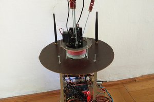
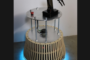
This is a robot platform with stereo cameras and omniwheel drive. It can be connected to HMD (e.g., google cardboad, ocolus rift, ...)

Similar projects worth following
We want to build a robot platform prototype, what can be used to experiment with telepresence augmented with virtual reality headsets, and controllers.
The goal of the project is to make an universal base, what can be upgraded with custom parts to solve specific problems.

This robot will be useful for example in dangerous, or hazardous situations. Like in a hospital where there is an outbreak. This robot can help in logistical tasks, like relocating the patients, manage supplies, and similar tasks.

We continuously research areas where this robot can be helpful, and effective.

The robot:
This robot can be remote controlled by 3 axis joystick or gamepad. We plan to add more supported controllers in the future.

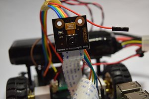
You can see what the robot see, with two 720p cameras. The cameras are mounted on the robot head, with 3 axis gimbals (yaw, pitch and roll) with head tracking.

We used 4 omniwheels to grant movement freedom, with the a lowest reaction time.

UPDATE: current version: https://hackaday.io/project/26073-bstya-v15

----------------

For the most detailed description please check out the project logs.

In the current state this robot can be used to demonstrate the possibility of this project, and 3D telepresence.

It is streaming video on wifi, and listen multiple sockets for head tracking control, and movement control.

You can connect to the robot with HTML5 compatible browser and watch the video stream. Because of the HTML5 we can send the mobil device orientation back to the robot, so it can adjust the camera position in real time. You can control the robot movement with joystick connected to PC, or tablet.

Currently you have to use a powerful mobil device for high resolution video. Probably we will optimize the webpage with the video stream to the new google cardboard, or similar mobil VR devices for better experience, but our goal is to make this robot usable, with the most advanced VR equipment.
(we are using the version one google cardboard made from a pizza box for developing : )

We got a possibility to try out the robot with Oculus Rift DK2, so currently we are working on the Rift compatibility. With the Rift we think we can upgrade the user experience to the next level. And we will face new level of problems to solve. (like motion sickness while driving around the robot)

If you don't know something what we did, why we did that way, feel free to ask, and I will try to answer it.

We are glad if you make suggestions, or tell your ideas to improve our robot.

UPDATE: 2016-09-13

We had an opportunity to present our robot with the Oculus Rift DK2 at "DRONE PRIX HUNGARY ÉS A DRÓNVERSENY & ROBOTIKA SHOW" We go a lot of positive feedback.

You can view the images here: http://hungarianrobot.hu/wordpress/multbeli-esemenyek/dronverseny-es-robotika-show-2016-szeptember-10/

View all 11 components

  • Working HMD support

    BTom08/20/2016 at 16:53 0 comments

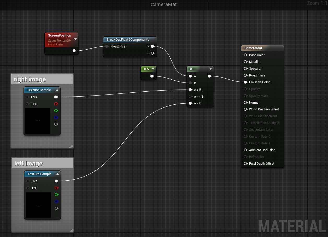
    The in-game browser approach is good for now. I finally solved to display the two camera image to separate eyes near real time.

    I used two browser to display the separate images. I found this solution, how to display different images to each eye.

    split-post-processing

    My solution is similar, but consist of a webBrowser, and SceneCaptureComponent2D to fill the left, or right eye image:

    I think the new version of the unreal engine, and the separated html files fixed the previous latency problems.

    In the future, I will try the engine built in media stream reader to display the video. But currently it can't read mjpeg_streamer.

  • Progress with the Oculus Rift DK2

    BTom07/04/2016 at 21:37 0 comments

    Working with the Ocolus Rift is a bit more complex than a google cardboard solution.

    The google cardboard is a simple concept. (https://vr.google.com/cardboard/)
    The mobil phone displays separate picture to each eye. In our robot we display the two camera picture for each eye. This makes the 3D picture. For the phone we used a simple browser page which shows the the left camera stream on the left side, and the right camera stream on the right side of the display. For the motion tracking I used the HTML5 device orientation events (https://w3c.github.io/deviceorientation/spec-source-orientation.html)

    The concept behind the Oculus Rift is the same, it's displaying separate picture for each eye. But there are lots of other important differences. The Oculus Rift is designed to be used for computer generated VR.

    My first idea was to display the image from the same browser page what I used in the mobil VR,
    I never worked on the Oculus Rfit before, so when I started, I quickly realized this isn't another computer monitor to drag and drop windows application on to it.

    So I started to search solutions to display streaming video on the headset.

    In the first experiments I used the web approach. I tried out the webVR. I made some progress with it.
    I programmed the head movement tracking easily, and send it to the robot with the same websocket solution what I used for the mobil VR. But I can't display the stream in the headset. I used the A-frame with webVR. I can display 3D objects, images, even recorded mp4 video, but not the stream.
    The robot is using mjpeg streamer to send the video over WIFI. It's not supported with the A-frame yet.

    I continued the search, and tried out a more native approach.

    My next experiment was the Unreal Engine. I chose it because in the end I like to have multiple VR headset support. The Unreal Engine is compatible with lots of headsets (like webVR), and I have a some experience with it.
    I started the programming with a new socket connection to the robot, because it couldn't connect to the websocket. In the Unreal Engine there is socket library, but I couldn't make a TCP client with it. So I made an UDP client in the Engine, and the UDP server in the robot. (In the basic concept, the robot is the server.)
    The next thing is the image. It was a bit tricky to display the stream in the engine. I used the experimental "ingame" browser widget. But the widget isn't optimized for VR displaying. My next idea was to display the browser in front of the player character, and lock it to the view. It worked, but It automatically converted for the VR headset display. If you look through the headset you see the two images with one eye. Basically it's showing a floating browser in front of the user with the two camera stream.

    I wanted to demonstrate it on a meetup, so I changed the side by side images to one camera picture, and showed that on the virtual browser in the unreal engine, with head tracking. For now it can show 2D video with head tracking. It's an interesting experience, but not what I was looking for.

    Now I'm thinking about if I can't make it work with Unreal Engine soon I will try out the native approach. Maybe with the Oculus Rift SDK I can display the two stream on the headset easily, and send the head tracking data to the robot.

    At the meetup we had issues with the WIFI connection again, like at the competition.
    We have to solve this once and for all before another public presentation. On the meetup we experienced high latency, and disconnects because of the poor connection.
    To solve this we will install an 5Ghz WIFI AP, or maybe a router on the robot.

  • Programming solutions

    BTom05/29/2016 at 14:21 0 comments

    We are running multiple programs on the robot. We used C++ (with openCV), python, Arduino programming on various tasks in the project.

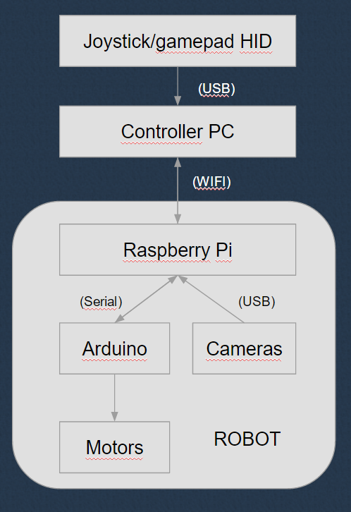
    This is the connection schematic between the programs (and hardware)

    The raspberry Pi on the robot is configured to a wifi access point, we can connect to the robot with multiple devices.

    The PC is the remote controlling machine. It sends the connected joystick command to the robot via sockets by a python program. In this program we can set deadzones, for precise control.

    We using separate sockets for the movement control from the joystick, and for the head tracking.

    On the raspberry Pi we are running multiple programs. Two socket servers, and two mjpeg stream server.

    One socket server is for the movement of the robot. In this python program we sending the servo speeds forward to the Arduino. In the arduino there is a simple program what is mapping the speed values to the servo positions. Because we modified the wheel driving servo to continuous rotation, we can control the movement speed with the servo position. The servo center position is where the wheel is stopped. Positive values make the servos turn forward at a given speed, and negative values make the servos turn backward at a given speed. On the arduinos we can set the servos center position for small adjustments.

    We made another socket program for the head movement. In this program we sending degrees to the second arduino. On the arduino we mapping this to servo positions. In the arduino program we can limit the servo movement to the physical limits of the mechanic.

    For the video stream we are using mjpeg streamer solution. We can connect to the stream for example with browsers, openCV applications, FFMPEG player, VLC player. So its really universal.

    In the current experimental setup we are steaming 640x360 videos without mjpeg encoding on two separate ports. We can connect to this stream via mobil browser, and display the two picture in real time. With HTML5 device orientation and websockets, we sending back the position data from the phone to the raspberry Pi. For remote controlling the robot we are using a Logitech Extrem Pro 3D joystick. With this setup we can use small windows tablet to send the joystick data to the robot, and a simple android, or iOs phone with HTML5 compatible browser, to demonstrate our robot at meetups.

    We only using low resolution video, for the experimenting, because the android phone what we use can't decode high resolution stream in real time. On PC we can easily achieve 720p video in real time. The another reason for the low resolution is, the low quality of the cardboard what we are using. It's only good for the proof of concept, not for the real usage.

    In the next phase we will connect the robot to an Oculus Rift DK2. It will be a little more complicated to us, to make possible for everyone to try out our robot at meetups, and similar events. But we think it will be more spectacular, with higher resolution and much more comfortable headset.

  • Electronic solutions

    BTom05/29/2016 at 13:11 0 comments

    We tried to keep the robot simple as possible. So we used raspberry pi 3, with arduinos, because there is lots of learning materials, easily to get, and open source.

    We are using three different voltage levels.

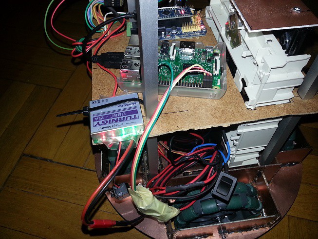
    This is a work in progress picture with only one arduino, and the CD drive is not


    For the raspberry Pi, we are using a simple voltage regulator connected to the battery, and the raspberry Pi 5V, and GND pins.

    The Arduinos connected to the raspberry Pi via USB cable. Because we connected the voltage regulator directly to the Pi GPIO, we can supply enough power to the two arduinos, and the two cameras. This way we don't need to use a powered USB hub.

    The servo motors need 6V to the maximum performance, but much more current than the raspberry Pi. So we used a separate electronic for this. We bought a Turnigy UBEC (15A). We used this device in the past. On the UBEC there is a voltage selector. We currently drive the servos with 5V.

    For the elevator (the CD drive mechanic) we need 12V. We connected this to a relay switch, with two limit switches. The first arduino controlling the relay.

    To simplify the development there is two switches. One for turning on the controllers, raspberry Pi, and arduinos. The other switch (built in the UBEC) is used to turn on the motors.

    For the programing, and video feed testing we can turn on only the controllers.

  • Mechanical solutions

    BTom05/29/2016 at 11:43 0 comments

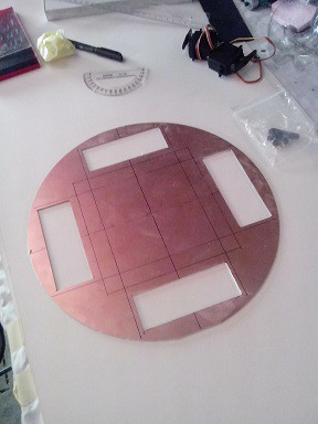
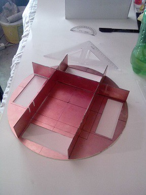
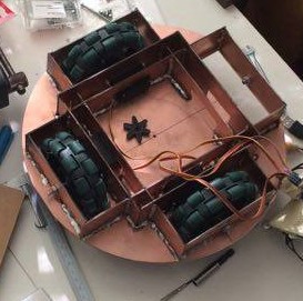
    The chassis consist of multiple levels. On the first level there are the motors, and the battery. And currently a special part for the "Magyarok a Marson" competition.

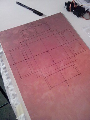
    The robot chassis made of PCB boards. The boards fixed with soldering. This make a solid base for the robot.

    We used omniwheels because this way the robot can freely move every direction. There is some other solutions, but for our plans in the future, we need fast direction changing reaction. We selected the four wheel layout, because in the past we built a robot with three wheel layout, and we need more traction, and carrying capacity this time.

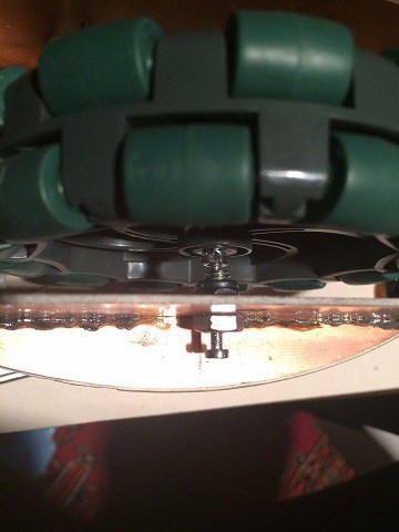
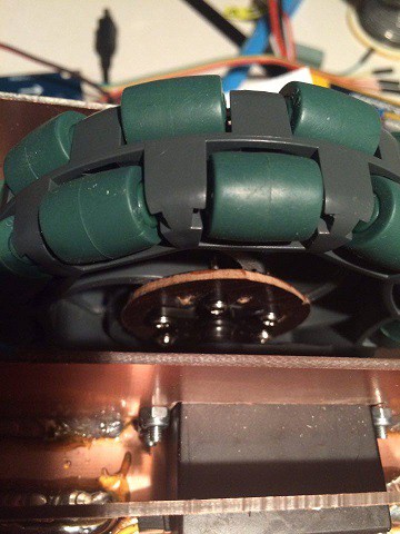
    The chassis of the robot is designed to be able to carry lots of weight. We are using supported axles for the wheels, to reduce the stress on the servo motor.

    On this picture this is a screw, with a hole in it. We don't use bearings for now, but in the future, if we have some problems with this solution we will upgrade it.

    On the serve side of the wheel, we use a custom clutch. It's made from a thin plywood, glued with epoxy to the wheel. The servo adapter secure the whole part with screws. Mostly the support from the other side make it really stable.

    We placed the battery the lowest point on the robot, to keep the center of gravity near to the ground.

    It is possible to place two 12V 7Ah battery on the robot, but with one battery it can be used about 12 hours with one charge.

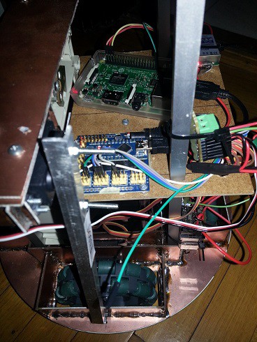
    On the second level, above the battery there are the electronics. We used aluminium spacers between the levels. In the rectangular aluminum profile we used threaded rod with nuts.

    The second level floor made of plywood, so this way we can easily tie down the electronics.

    On the left side of the picture there is a mechanical part from a CD drive. On the "Magyarok a Marson" competition we have to insert in the holes of PVC pipes, a signaler fixed to the robot "arm" (the aluminium stick connected to the CD drive). The holes were positioned on the pipes in two heights. The CD drive mechanic served as an elevator to, move the signaler up, and down. We used the servo connected to the elevator to hang out the signaler. when we near to a pipe. We can't left the signaler hang out from the robot, while we drive around the pipes, because of the competition rules.

    In the future, we will replace this "arm" for a more useful one.

    The top level of the robot is also made of plywood.

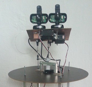
    This is the head of the robot. The base of the head made of rectangular aluminum profile fastened to the plywood,

    We used only 3 servo to achieve 3 degrees of freedom. The servos connected to the main axle with ball joints. And there is a drive shaft coupling near the upper two servos. It can't carry lots of weight, but the two camera works well with it.

    In the future, we will reinforce this, because when we drive the robot with maximum speed this is a bit unstable

  • History of the project

    BTom05/29/2016 at 09:41 0 comments

    First we build this robot to a competition called "Magyarok a Marson". In this competition every year there is a new challenge.

    We planed this robot for multiple use, not only for this competition. We adapted our ideas to the requirement of the competition. Like the size limit, weight limit, and form (column chassis)

    Our plans was bigger than the time, and budget we can use to build the robot, because we ran into lots of problems to solve. For the competition we can't finish the head movement part, so we used a fixed cameras, but everything else worked fine.

    On the competition we faced another problem, what we can't solve there. The robot uses the Raspberry Pi 3 on-board WIFI adapter. It's a good adapter, if there isn't another 30+ wifi device near it. We tried to use 5Ghz wifi USB sticks what we bought hours before the competition, but couldn't get it work on the Pi in time. (the competition was at the weekend, so every big shop was closed) We got some points on the competition, but from an outsider perspective our robot worked poorly.

    After the competition we learned the conclusions. We will use a WIFI Acces Point on the robot itself. In the past, we used unifi ubiquiti access points in similar situations, and it worked well.

    Before the competition the robot worked well in our test, we never think about the connection. We were a bit sad because we couldn't present a robot in it's full glory, but we learnt a lot from building the robot.

    We like going to competitions like this, for the learning. Every time we face new problems, we learn something from it. On the upcoming post I will summarize the topic, and the greatest challenges what we were faced while we building/developing this robot.

View all 6 project logs

Enjoy this project?

Share

Discussions

BTom wrote 07/23/2017 at 15:01 point

Thank you for the comments, this is the current version of the robot: https://hackaday.io/project/26073-bstya-v15

  Are you sure? yes | no

hunterjamesmatthewss wrote 02/16/2017 at 18:41 point

will you be making a tutorial on how this was built? 

  Are you sure? yes | no

BTom wrote 07/23/2017 at 15:00 point

Sorry, but I can't make a whole tutorial, mostly because it isn't complete, and if I have time to work on it, I'm working on improvements not documentation :/

But if you have specific questions about replicating it, feel free to ask.

  Are you sure? yes | no

George I Fomitchev wrote 08/12/2016 at 11:13 point

combination of VR and telepresence really exciting... a big market potential for disabled people...

  Are you sure? yes | no

George I Fomitchev wrote 08/12/2016 at 11:13 point

interesing... very similar to what we do... http://endurancerobots.com/en/robots/telepresence-robot-rig-system/

  Are you sure? yes | no

Similar Projects

Does this project spark your interest?

Become a member to follow this project and never miss any updates