Common Anode LED Control
How to hook up a 7-segment common anode display to Arduino
How to hook up a 7-segment common anode display to Arduino
To make the experience fit your profile, pick a username and tell us what interests you.
We found and based on your interests.
kem-18011.inoArduino demo sketchino - 3.85 kB - 05/29/2016 at 20:36 |
|
The final piece of the puzzle is a bit of Arduino code necessary to display numbers on the digit. Thanks to the 74HC595 shift register software control of the LED segments is really easy. First we define the segments like this:
#define SEGMENT_A 1
#define SEGMENT_B 2
#define SEGMENT_C 4
#define SEGMENT_D 8
#define SEGMENT_E 16
#define SEGMENT_F 32
#define SEGMENT_G 64
Next up we declare a lookup table:
/* using a pre-defined lookup table saves time and memory! */
const byte digits_lot[] = { SEGMENT_A | SEGMENT_B | SEGMENT_C | SEGMENT_D | SEGMENT_E | SEGMENT_F,
                      SEGMENT_B | SEGMENT_C,
                      SEGMENT_A | SEGMENT_B | SEGMENT_D | SEGMENT_E | SEGMENT_G,
                      SEGMENT_A | SEGMENT_B | SEGMENT_C | SEGMENT_D | SEGMENT_G,
                      SEGMENT_B | SEGMENT_C | SEGMENT_F | SEGMENT_G,
                      SEGMENT_A | SEGMENT_C | SEGMENT_D | SEGMENT_F | SEGMENT_G,
                      SEGMENT_A | SEGMENT_C | SEGMENT_D | SEGMENT_E | SEGMENT_F | SEGMENT_G,
                      SEGMENT_A | SEGMENT_B | SEGMENT_C,
                      SEGMENT_A | SEGMENT_B | SEGMENT_C | SEGMENT_D | SEGMENT_E | SEGMENT_F | SEGMENT_G,
                      SEGMENT_A | SEGMENT_B | SEGMENT_C | SEGMENT_F | SEGMENT_G,
                      };
Now this is all we need to display a number. Note this is a Quick & Dirty method without array boundary checks etc
void print_number( byte number )
{
  shiftOut( digits_lot[ number ] );
}

void shiftOut(byte dataOut) {
  int i=0;
  int pinState;

  digitalWrite(latchPin, 0);
  digitalWrite(dataPin, 0);
  digitalWrite(clockPin, 0);

  for (i=7; i>=0; i--)
{
    digitalWrite(clockPin, 0);
    if ( dataOut & (1<<i) ) {
      pinState= 1;
    }
    else {
      pinState= 0;
    }
    digitalWrite(dataPin, pinState);
    digitalWrite(clockPin, 1);
    digitalWrite(dataPin, 0);
  }
  digitalWrite(clockPin, 0);
  digitalWrite(latchPin, 1);
}
Full source code for an Arduino demo sketch can be downloaded in the Files section
By using a 74HC595 Cascading Shift Register to toggle the ULN2803 inputs it's possible to (un)set any number of display segments by writing a single byte to the data port. This would reduce, simplify and speed up the code needed to control the display. Back to the breadboard!

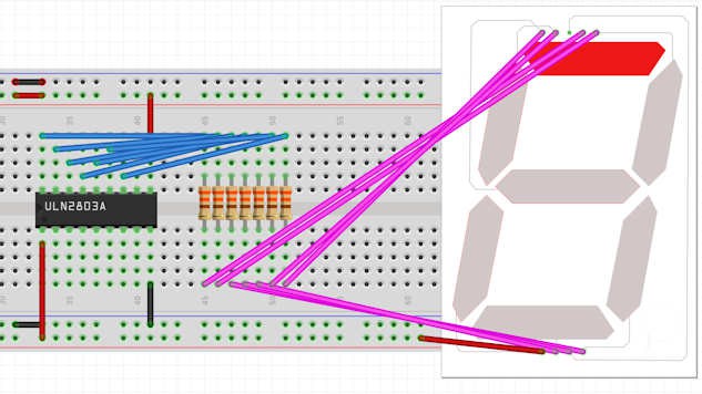
The 595's outputs Q0 to Q6 are hooked up to input 1B to 7B. The clock, latch and data pins are wired to my Nano. I'm using pin D10 to D12 but other digital pins would work as well. Note that i'm using an external 5V power supply to power the circuit and that the Nano, which uses USB power, is wired to common ground. The Nano onboard 5V supply would probably manage to power a single digit but I'm not taking any chances and want to be able to add more digits in the future. Adding digits is simply a matter of adding a Darlington driver and cascading a second shift register by hooking up its DS serial input to the Q7" serial out pin of the first 595.
Now all that's left to do is to write the code that will make it all happen.
Controlling a 7 segment digit is usually done with a MAX7219 chip but they are geared towards common cathode displays. Digits and segments can be swapped to drive common anode type displays but this requires extra software and it probably can not sink the current & voltage needed for larger, multiple-led-per-segment displays.
The ULN2803 is a cheap and common 8-channel Darlington driver chip that can sink up to 500mA per pin at 50V. That's plenty of headroom to drive my digits so it's time to get out the breadboard.

The image above shows the Darlington IC wired up to the display segments. Output pin 1C controls segment A, pin 2C segment B etcetera. The digit common anode and COM are hooked up to +5V and GND to ground. Input pin 1B is held high here to light up segment A. Note the 7 current limiting resistors that will protect the segment leds from burning out.
Now i could wire inputs 1B to 7B to a digital pin on my Arduino but that would have two big disadvantages: it takes up 7 digital I/O pins and requires lots of digitalWrite() calls to switch on the segments needed for each digit. So I decided to shift the workload to a shift register.
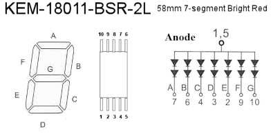
The large digits really got me excited but Googling the part number KEM-18011-BSR-2L did not yield a lot of information. But the lack of a decimal point suggested the standard pinout mapping did not apply. So I took a 5V power supply, some DuPont cables and a 330 Ohm current limiting resistor and started prodding the pins. Nothing happened. I wondered if it could be a common anode display, switched polarity of my wiring and bingo!
I managed to work out the LCD pinout and it goes like this:

Note that pin 8 is not used; this is where the missing DP segment would have connected.
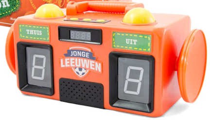
Because my hobby budget is close to zero I often search thrift stores and fleamarkets for electronic junk i can salvage for parts. I recently found a toy soccer scoreboard / game timer that was fully functional for only 1 euro.

Create an account to leave a comment. Already have an account? Log In.
Become a member to follow this project and never miss any updates